Table of Contents
Advertisement
Quick Links
Advertisement
Table of Contents

Subscribe to Our Youtube Channel
Related Manuals for Zünd S3 Series


Summary of Contents for Zünd S3 Series
- Page 1 Operating Manual S3 Digital Cutter...
- Page 2 Keep it in a safe place for future use! Original operating manual Software/Firmware version: FW1.71 Creation date: 05-2019...
-
Page 3: Table Of Contents
Contents Contents 1 Introduction............................7 1.1 Using the operating manual......................8 1.2 Points to note when reading this operating manual.................9 1.3 Publishing details..........................9 2 Product description........................11 2.1 Important information about the product..................11 2.2 Orientation............................12 2.3 Product identification........................13 2.4 Intended use........................... 13 2.5 Cutter overview..........................14 2.6 Modules, tools..........................16 2.7 Material handling.......................... - Page 4 Contents 4.5 General settings..........................75 4.6 User level............................76 4.7 Malfunctions............................ 78 4.8 Daily checks prior to start-up......................81 4.9 Behavior in dangerous situations....................81 4.10 Start-up............................83 4.11 operating mode..........................85 4.12 Moving the beam/module manually....................87 4.13 Handling modules/tools.........................88 4.14 Material fixing..........................102 4.15 Material transport (optional)......................110 4.16 Automatic tool initialization - AKI (optional)................114 4.17 Job processes..........................119...
- Page 5 Contents 8 Modules............................209 9 Material handling.......................... 211 10 Additional specifications......................213...
- Page 6 Contents...
-
Page 7: Introduction
Introduction 1 Introduction Dear customer, With your decision to purchase our product you are participating in the worldwide success of Zünd cutter systems. The modular design of our systems provides the following benefits, among others things: • A system solution that meets your individual requirements in terms of speed and quality. •... -
Page 8: Using The Operating Manual
Introduction 1.1 Using the operating manual The supplied operating manual is intended to enable you to operate the machine safely, perform routine maintenance and use the machine optimally in every way. To do this, you need to be able to find what you need in the documentation. Scope of the operating manual Volume 1 - Operating instructions This volume contains information on engineering, commissioning, operation... -
Page 9: Points To Note When Reading This Operating Manual
Dimensional information Dimensional information is listed in the SI/US units, depending on the installation site. 1.3 Publishing details Designation Operating instructions for S3 series cutters. Layout, illustration, and print Zünd Systemtechnik AG - Technical Communications Department © Copyright... - Page 10 Introduction...
-
Page 11: Product Description
Product description 2 Product description This chapter contains information on the following: • Representation conventions in the operating manual • Usage possibilities of the machine • Structure of the main components • Important technical data • General technical description of the machine 2.1 Important information about the product Tip: "Tip"... -
Page 12: Orientation
Product description 2.2 Orientation Directions such as "right, left" or "front, back" relate to the operator's view of the machine during operation. front rear right left X-axis Y axis... -
Page 13: Product Identification
Product description 2.3 Product identification 2.3.1 Rating plate Position of the signs Year of manufacture Rating plate Serial number Additional UL sign UL mark of conformity Additional connection values Nominal voltage Additional FCC sign Rated current CE mark of conformity Frequency UL functional safety Nominal voltage... -
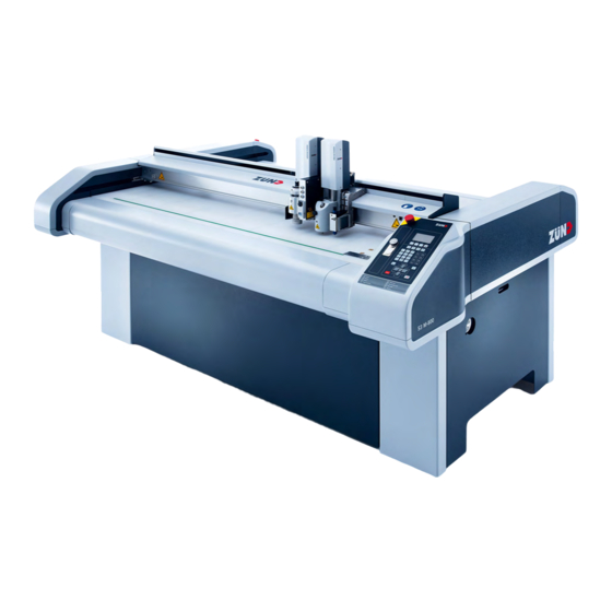
Page 14: Cutter Overview
Product description 2.5 Cutter overview... - Page 15 Product description Air supply to maintenance units Beam Tool/module power supply Extractor Workstation Control panel with optional workstation Vacuum pump Working area...
-
Page 16: Modules, Tools
Product description 2.6 Modules, tools Zünd cutters are highly specialized and can be easily converted to process other materials through the use of modules and tools. Two modules can be attached to slots 1 and 2 on the module carriage as standard. Either an electrically or pneumatically driven marking module can be installed in slot 3 (MAM-SP, MAM-SE). - Page 17 Product description 2.6.1 Universal applications Universal modules - UM-S Universally applicable carrier module for a wide range of tools. Tools for use in the UM Electric Oscillating Tool - EOT Cutting tool with high oscillation frequency for soft and medium hard materials.
- Page 18 Product description Scoring Cutting Tool - SCT Combination tool for scoring and cutting cardboard and coating blankets of up to 5 mm material thickness. V-Cut Tool - VCT Tool with five different cutting angles. Creation of complex 3D constructions from high expansion foam or sandwich boards. Passepartout Tool - PPT Exact 45°...
- Page 19 Product description 2.6.2 Routing, engraving: Router modules - RM-S Universally usable routing system, fitted with a powerful high frequency spindle. • Routing depth up to 25 mm • Effective dust extraction, actively air-cooled • Surface compensation for precise depth setting •...
- Page 20 Product description Punch and Pricking Module - PPM-S: High-performance tool for perforating leather, rubber and textile materials with up to 8 holes per second. A marking tool is integrated. 2.6.4 Kiss-cutting Kiss-cut module - KCM-S KCM-S: This module cuts films with the highest precision and processing speed without damaging the carrier material.
-
Page 21: Material Handling
Product description 2.6.5 Drawing, marking, labeling Marker modules - MAM Marking and labeling of various types of materials. Use of standard commercial leads. • MAM-SE: 1 drawing tool, electric • MAM-SP: 1 drawing tool, pneumatic • MAM-SPS: 1 drawing tool, pneumatic MAM-SPD: 2 drawing tool, pneumatic •... - Page 22 Product description Cutter with material transport The material transport is used to pull the processing materials onto the work surface. The conveyor belt is used as a cutting base and conveyor belt at the same time. During processing, the material to be processed is fixed in place using a vacuum.
-
Page 23: Options
Product description 2.8 Options 2.8.1 Laser pointer The laser pointer is used as an aid for the precise definition of the reference point. It also serves for the connection of electrically driven tools. 2.8.2 ICC camera The ICC camera allows perfect registration in which the exact position of printed material on the processing surface is determined. -
Page 24: Accessories Box
Product description 2.9 Accessories box The accessories box is delivered with the cutter. The accessories box contains the tools and operating and auxiliary materials needed for maintaining the cutter. The contents are provided appropriately for the cutter. Contents (sample) Accessories Quantity Task Conveyor... -
Page 25: Technical Description
The air pressure for the respective consumers is adjusted via a maintenance unit. The maintenance unit is accessible via service doors for adjusting settings and carrying out maintenance work. 2.10.2 Movement system The S3 series has four electronically driven axes: Axis Function... - Page 26 Product description signals and compressed air via an energy chain. All drive parts are protected against direct access or contamination using covers. X axis - material transport Material transport takes place via conveyor clamp elements and feeding clamps on the bar. Feed takes place via the bar movement.
-
Page 27: Technical Data
Product description 2.11 Technical data 2.11.1 Dimensions 2.11.1.1 Base cutter (mm) The effectively usable working surface (D x E) depends on the tool or module. Type (mm) M-800 1542 M-1200 2086 1942 1230 1330 M-1600 2342 1630 L-1200 1942 1230 2556 1800 L-1600... - Page 28 Product description 2.11.1.2 Base cutter (inch) The effectively usable working surface (D x E) depends on the tool or module. Type (in) M-800 60.7 32.7 M-1200 82.1 76.5 48.4 52.4 M-1600 92.2 64.2 32.7 20.5 L-1200 48.4 48.4 70.9 70.9 L-1600 92.2 64.2...
- Page 29 Product description 2.11.1.3 Cutter extension - CE (mm) Type CE0800 CE1200 CE1600 Length (mm) 1275 1674 M-800 M-1200 M-1600 L-1200 L-1600 XL-1200...
- Page 30 Product description 2.11.1.4 Cutter extension - CE (inch) Type CE0800 CE1200 CE1600 Length (in) 34.4 50.2 65.9 M-800 M-1200 M-1600 L-1200 L-1600 XL-1200...
- Page 31 Product description 2.11.2 Weights 2.11.2.1 Base cutter (kg) Type Weight (kg) max. floor load (kg/m) M-800 M-1200 M-1600 L-1200 L-1600 XL-1200 2.11.2.2 Base cutter (lbs) Type Weight (lbs) max. floor load (lbs/in) M-800 M-1200 1080 M-1600 1240 L-1200 1240 L-1600 1350 XL-1200 1370...
- Page 32 Product description Type max. material weight (lbs) max. material weight (lbs/in XL-1200 2.11.3 Electrical connection, power consumption Electrical connection 400 V, 50/60 Hz Value Voltage 3-phase, 400 VL1, L2, L3, N, PE Mains frequency 50/60 Hz Power input - 3 phases (without vacuum generator) 3.0 kW Current consumption, 3 phases (without vacuum generator) max.
- Page 33 Product description Value Mains fuse, min. 16 A 2.2 kW vacuum pump Value Voltage 3-phase, 400 V L1, L2, L3, PE Mains frequency 50/60 Hz Power input - 3 phases 2.2 KW Mains fuse, min. 16 A 2.55 kW vacuum pump Value Voltage 3-phase, 208 V L1, L2, L3, PE...
- Page 34 Product description Value Mains frequency 50/60 Hz Power input - 3 phases 4.6 KW Mains fuse, min. 20 A Vacuum turbine 1 - 9 kW Value Voltage 3-phase, 400 V L1, L2, L3, PE Mains frequency 50/60 Hz Power input - 3 phases 1 - 9 KW Mains fuse, min.
- Page 35 Product description • Air consumption: base machine 20 l/min. 20 - 400 l/min depending on configuration 2.11.5.2 Compressed air settings Compressed air regulator P1 Air pressure [MPa] max. air consumption [l/min] Maintenance unit House connection Punch modules - PUM-S, PMM-S, 0.7 - 0.8 0.7 - 1.0 PPM-S...
- Page 36 <75 dB and ~85 dB. Electromagnetic emissions The S3 series meets the requirements of the following technical standards: • EN 61000-6-2 EMC, interference resistance in industrial environments •...
- Page 37 Product description Please ask the manufacturer if you wish to view to the test reports. FCC approval NOTE: This equipment has been tested and found to comply with the limits for a Class A digital device, pursuant to part 15 of the FCC Rules. These limits are designed to provide reasonable protection against harmful interference when the equipment is operated in a commercial environment.
- Page 38 Product description...
-
Page 39: Safety
Safety 3 Safety This chapter contains information on the following: • Definition of the intended use of the machine • Generally applicable safety instructions and safety regulations to be observed • Explanation of the meaning of symbols and pictograms which are used in this manual and in signs on the machine •... - Page 40 Safety • Use of materials that are not defined in the contract and in this operating manual. • Failure to observe the applicable parameters for the processing of the relevant material. • Maintenance work on an unsafe machine. • Failure to follow the operating instructions. •...
-
Page 41: Hazard Warnings, Important Instructions
Safety 3.4 Hazard warnings, important instructions Explanation of the notes Both in the operating manual and on the device itself, dangers and important instructions are designated by special symbols and signal words as follows: Danger: The safety instruction Danger • refers to imminent danger •... - Page 42 Safety Tip: Tip in combination with the light bulb refers to user tips and useful information which enhance the usability, prolong the service life of the machine and make the work significantly easier. Tip: With tips combined with the sheet, we provide usage tips and useful information which can improve the energy efficiency of the machine or optimize its environmental effects.
-
Page 43: Areas Of Responsibility
Safety 3.5 Areas of responsibility Manufacturer's areas of responsibility • The manufacturer is responsible for the safe condition of the machine on delivery, including operating manual and accessories, according to the sales documentation. Areas of responsibility of the owner or person authorised by them: •... -
Page 44: Personal Protective Equipment
Safety 3.7 Personal protective equipment The safety equipment required for operating the machine is dependent on the following factors: • Module and tool system used • Processing material used When operating the machine or carrying out maintenance or servicing work, wear tight fitting clothing and appropriate personal protective equipment. -
Page 45: Rules And Occupational Safety
Safety 3.8 Rules and occupational safety • Operation of the machine is always subject to local regulations regarding work safety and accident prevention. • Make sure that there is adequate lighting during operation. • Check protective devices every time before starting the machine. •... -
Page 46: Danger Areas
Safety 3.10 Danger areas 3.10.1 General danger area Danger area The danger area is restricted to the working area or the active area of the drive system. Never reach into this work area during processing. 3.10.2 Danger area during initialization Caution: Risk of injury during manual initialization of the tool! The safety devices are not active during manual initialization... - Page 47 Safety • For initialization, use automatic AKI initialization, if the tool allows this. Module (e.g., UM-S) Tool (e.g., UCT) Danger area Safety distance during initialization (25 cm) The safety distance (d) for operating personnel during manual initialization is 25 cm. Do not reach into the marked danger area during the initialization phase! 3.10.3 Danger area during cleaning Caution:...
- Page 48 Safety • While cleaning work is being performed, attach a sign that says "DO NOT SWITCH ON" that is prominently displayed on the main control panel of the machine. Danger area...
-
Page 49: Warnings On The Product
Safety 3.11 Warnings on the product The warnings on the modules and tools are illustrated in the respective operating instructions. Description Variant 1 (CE) Variant 2 (ANSI) Mandatory sign: Wear protective gloves Art. no.: 5800412 (50 mm) Art. no.: 5801106 (65 mm) Mandatory sign: Wear eye protection Art. - Page 50 Safety Description Variant 1 (CE) Variant 2 (ANSI) Warning sign: Hand injuries due to crushing Art. no.: 5800342 (50 mm) Art. no.: 5801059 (65 mm) Warning sign: Electrical hazard Art. no.: Art. no.: 5801338 (50 mm) 5802331 (95 mm) Warning sign: Electrical hazard Art.
-
Page 51: Protective Devices
Safety 3.12 Protective devices EMERGENCY STOP control device Safety device (protective trip switch) EMERGENCY STOP control device Control panel 3.12.1 Safety device Caution: The beam may cause serious injuries in case of a collision. Note that the high level of kinetic energy of the drive results in a significant braking distance. Light barriers are no guarantee against injuries! The protective system consists of light barriers on the bar ends and on the module carriage. - Page 52 Safety Effects for the cutter • The drive motors (beams, module carriage) are slowed to a standstill. • The Z-axis remains in the position where it is located when the safety device is triggered (e.g. lower position). • The cutter switches to STOPPED mode. •...
- Page 53 Safety Do not use EMERGENCY STOP control devices to switch off the machine under normal circumstances. Note: To unlock an activated EMERGENCY STOP control device after restoring operational safety, turn the switch clockwise (see Reset EMERGENCY STOP control devicesReset EMERGENCY STOP control devices on page 82Reset EMERGENCY STOP control devicesReset EMERGENCY...
- Page 54 Safety 3.12.4 Shutdown in an emergency An emergency shutdown allows the machine to be stopped quickly in case of emergency. Effects for the cutter • The drive motors (beams, module carriers) are braked to a standstill and are then disconnected from the energy supply.
-
Page 55: Mechanical Hazards
Safety 3.13 Mechanical hazards 3.13.1 Collection, retraction Caution: Risk of injury from entanglement, getting caught and being pulled in! The machine and the tool system has moving parts. Possible consequences • Bruises, crushing, lacerations to fingers or hands • Bruising to the head and arms •... -
Page 56: Risk Of Burns
Safety 3.13.3 Cut and puncture injuries Caution: Injury risk from sharp objects! Blades, router bits and punching inserts have very sharp edges which are sometimes hidden by moving equipment (spring-loaded gliding disc). Possible consequences • Cutting and stabbing injuries to the hands and arms Precautionary measures •... -
Page 57: Risks Arising From The Emission Of Toxic Dust
Safety 3.16 Risks arising from the emission of toxic dust Warning: Risk of poisoning from the emission of toxic dust! Processing certain materials can lead to the creation of harmful toxic dust. • Obtain information about the toxicity of the material to be processed from the manufacturer. •... -
Page 58: Environmental Hazards
Safety 3.18 Environmental hazards Warning: Processing residues, operating materials, cleaning agents etc. can cause damage and pollute the environment if they enter the soil, waterbodies or the sewage system. Explanation of the hazard label Hazard label for substances that are harmful to the environment Safety regulations and protective measures •... - Page 59 Safety Always wear your personal protective gear (protective gloves, goggles, mouth guard etc.) when handling chemicals. Explanation of the hazard label Hazard label for very toxic or toxic substances Hazard label for hazardous substances or irritant materials Hazard label for irritating substances...
- Page 60 Safety Note: Chemicals classified as irritants are used to operate and clean this machine (cleaning agents, operating fluids). Safety datasheets for the substances in question can be downloaded from the Zünd homepage (www.zund.com). Safe handling of chemicals Important: Dispose of chemicals in accordance with national regulations. Follow the manufacturer's instructions (MSDS).
-
Page 61: Risk Of Fire And Explosion
Safety 3.20 Risk of fire and explosion Warning: There is a risk of fire when routing and cutting flammable materials Terminate the routing/cutting and leave the tool to cool off in case of • smoke emission. • Discolorations on the router/blade which point to increased heat development Warning: Risk of dust explosions Flying sparks or electrostatic charges result in the risk of dust explosions during the extraction of... -
Page 62: Danger From Laser Beam
Safety Combustible gases: e.g. methane, propane, etc. Behaviour in the event of a fire • Turn off the machine using the main switch • Assess the situation: If there is danger, leave the area immediately and call the fire department. Only try to extinguish the fire if your personal safety is not at risk. -
Page 63: Safety Precautions For Service Personnel
Safety 3.23 Safety precautions for service personnel The reliability, readiness and service life of the machine greatly depend on you carrying out your work in a conscientious manner. Note: Specialist knowledge and expertise are required to service and maintain the machine. The manufacturer provides this knowledge through training courses which are specially tailored for service personnel. - Page 64 Safety...
-
Page 65: Controls And Operation
Controls and operation 4 Controls and operation This chapter familiarizes you with the controls, guides you through the operational procedures and describes the following operating steps: • Daily commissioning • Operation of the main components • Detailed information on the operation of the machine •... -
Page 66: Controls
Controls and operation 4.2 Controls 4.2.1 Overview Rear EMERGENCY STOP control device Control panel and workstation (optional) Maintenance units (dependent on cutter configuration) - Page 67 Controls and operation 4.2.2 Control panel Display ONLINE key Soft keys STOP key Navigation keys VAC (vacuum) key Number block and function keys Router on/off key (optional) Tool up/down key Front processing approval (optional) Travel keys Switch on front vacuum (optional) SHIFT key EMERGENCY STOP control device...
- Page 68 Controls and operation 4.2.3 EMERGENCY STOP control devices Activating an EMERGENCY STOP control device triggers a machine standstill in the event of an emergency. The cutter is fitted with two EMERGENCY STOP control devices as standard. They are located as follows: •...
- Page 69 Controls and operation Note: Risk of damage to the cutter by activating EMERGENCY STOP control devices. Do not use EMERGENCY STOP control devices to switch off the machine under normal circumstances. Note: The activated EMERGENCY STOP control device remains locked in the off position. To unlock an activated EMERGENCY STOP control device after restoring operational safety, turn the switch clockwise (see on page 82).
- Page 70 Controls and operation The maintenance unit is preset and adjusted. Check the air pressure setting at regular intervals. The setting values can be found in the chapter Basic unit compressed air supply.
- Page 71 Controls and operation 4.2.5 Interfaces The machine has data exchange interfaces. These are attached to the electronics unit. not used USB (host) - not used Status and error display COM 1 COM 2...
-
Page 72: Menu Navigation
Controls and operation 4.3 Menu navigation 4.3.1 Navigation keys Functions in the cutter menu Use these keys to navigate through the menu • If submenus are available, use this key to change to the next menu level • Select setting/function Switching from a sub-menu to the previous menu level Function in the editor Use these keys to move the cursor to the right or left... -
Page 73: Menus And Functions
Controls and operation Information Function keys Allocation of the function keys Communication Settings such as: interface, port, IP address, mask, MAC address Switch between tabs with the key. Scroll up/down within the tab with the key. 4.3.4 Pop-ups, dialog boxes Pop-up menus or dialog boxes are displayed for the following actions: •... -
Page 74: Function Keys
Controls and operation 4.4.2 Selection Use the navigation keys to select an entry from the list. B Confirm the selection with OK and cancel by pressing ESC. 4.4.3 Select commands, functions Mark the required command with the navigation keys and select with The command can also be activated directly via the menu number. -
Page 75: General Settings
Controls and operation A Simultaneously press the SHIFT key and the function key (F1 - F8) for which you would like to change the function. B The function key selection window opens. C Enter the menu number of the desired menu entry using the number field. D Confirm the selection with OK or cancel by pressing ESC. -
Page 76: User Level
Controls and operation 4.5.3 Setting the display contrast Description Increase contrast Shift + Reduce contrast Shift + 4.5.4 Setting the volume Description Increase/decrease the volume Shift + 4.5.5 Clear buffer Clear the data buffer following the termination or processing of a job. Menu Description 2-4-1 Clear buffer... - Page 77 Controls and operation 4.6.2 Defining active user level after start-up Tip: After start-up, it is not possible to define a user level that is higher than your own as an active user level. A Change to the 4-3 Start user menu. B Select the desired user.
-
Page 78: Malfunctions
Controls and operation 4.7 Malfunctions 4.7.1 Troubleshooting Caution: Risk of injury due to incorrectly remedied faults. • Ensure that the error on the device is remedied correctly. • Contact your Zünd partner. Make note of the following information if you need help from the service department to rectify an error in your cutter: •... - Page 79 Controls and operation 4.7.2.2 Error shown on the status and error display The error is displayed as a sequence. All superfluous digits of the error code will be omitted in this display! If several errors occurred one after the other then these are combined together in a group. The error which occurred first is displayed at the start of the group.
- Page 80 Controls and operation • Contact your service partner if you have any problems with the energy supply. Note: Risk of damage to the cutter If an automatic circuit breaker has been triggered, the cause may be an electrical defect in a consumer.
-
Page 81: Daily Checks Prior To Start-Up
Controls and operation 4.8 Daily checks prior to start-up Caution: There is a risk of injury if the machine is damaged! Machine faults can result in defects and accidents. • Never start up a machine if it is damaged. • Report all defects and faults to your supervisor and arrange for them to be rectified immediately by qualified personnel. - Page 82 Controls and operation When a hazard or a possibly hazardous situation occurs, activate an EMERGENCY STOP control device immediately. Effects for the cutter • The drive motors (beams, module carriers) are braked to a standstill and are then disconnected from the energy supply. •...
-
Page 83: Start-Up
Controls and operation A Remove the object and restore operational safety. B Confirm the error message on the operating unit. C Bring the machine into ONLINE mode to continue processing. 4.10 Start-up 4.10.1 Switch on the machine Main switch, off position Main switch, on position Switch the main switch to the ON position (Pos. - Page 84 Controls and operation 4.10.2 Initialize the machine Caution: Risk of injury due to automatic starting of the machine Following initialization, OFFLINE mode is active. The cutter can receive commands from the operating software which activate the ONLINE mode. Do not start the operating software until after initialization of the machine. Press the function key on the operating unit.
-
Page 85: Operating Mode
Controls and operation 4.11 operating mode The cutter can be put into three operating modes: • OFFLINE • ONLINE • STOPPED A combination of keys can optionally be used to switch from any operating status to either of the other two operating modes. - Page 86 Controls and operation 4.11.3 STOPPED Note: The operating mode STOPPED protects the operator from the machine being set in motion using remote controls. In this operating mode, commands are received but they are not processed. Even commands from the operating software (e.g., to change to the ONLINE operating mode) are ignored. A red illuminated LED on the ONLINE key indicates that the operating mode STOPPED is active.
-
Page 87: Moving The Beam/Module Manually
Controls and operation 4.12 Moving the beam/module manually The module carriage can be moved using the travel keys in the OFFLINE and STOPPED operating modes. The assignment of the keys corresponds to the direction of travel. Pressing the SHIFT key at the same time will make the module carriage move faster. Pressing a travel key in the X and Y direction at the same time will make the module carriage move diagonally. -
Page 88: Handling Modules/Tools
Controls and operation 4.13 Handling modules/tools Modules are independently recognized by the cutter control unit. Tools, on the other hand, do not have automatic recognition and must be manually allocated to a module. Tool-specific parameters (initialization, moving speeds, acceleration) are saved to the corresponding tool and can be called up again at any time. - Page 89 Controls and operation 4.13.1 Module/tool/tool insert Module (e.g., KCM-S, UM-S) Tool (e.g. CT, UCT, EOT, POT) Tool insert: router, blade, pen...
- Page 90 Controls and operation 4.13.3 Inserting/replacing the module...
- Page 91 Controls and operation 4.13.3.1 Module carriage Module carriage, slot 1 Module carriage, slot 2 Module carriage, slot 3 (reserved for marking module MAM-SE, MAM-SP) Pneumatic connections Guide pins Laser pointer with electrical connections (optional)
- Page 92 Controls and operation 4.13.3.2 Inserting a module A Select 1-5-1 Change module/tool. The module carriage moves to the module change position. B Thread the module into the guide pin. C Lower the module until the stop. D Screw the module to the module carrier with the 4 mm Allen key (2x). Results The module is now mounted and is located by the software.
- Page 93 Controls and operation 4.13.4 Activating a module It is often necessary to activate a module in order to check the settings. This function can only be carried out in the main menu. The active module can for example be used as a pointer to define the vacuum width or the reference point.
- Page 94 Controls and operation 4.13.5 Marking the tool Label all tools of the same type with a consecutive number. Corresponding adhesive labels are supplied with the equipment. 4.13.6 Tool manager The tool manager is a user interface to handle tools in combination with a universal module (UM). A sensor on the module detects the presence of the inserted tool.
- Page 95 Controls and operation 4.13.6.1 Inserting/replacing the tool A Select 1-5-1 Change module/tool. B If necessary, select the module/tool change position. C Insert the tool and - if electrically or pneumatically driven - connect to the power supply. D Confirm the selection with OK. The tool manager opens.
- Page 96 Controls and operation 4.13.6.3 Selecting a tool already inserted A Insert the tool. B Select 1-1-1-1 Select tool in the menu. In the dialog, all tools already assigned to this module are listed. C Select the tool inserted. 4.13.6.4 Deleting a tool A 1-1-1-1 Select tool .
- Page 97 Controls and operation 4.13.7 Connecting powered tools Driven tools (e.g. EOT, DRT, POT) require an energy supply (electrical, pneumatic). This energy supply is controlled by the cutter control unit. Electrically driven tools are connected to the connector control of the laser pointer or the ICC camera (optional).
- Page 98 Controls and operation Procedure The tool is applied and assigned to the module. A Insert the tool into the color-coded connection provided. B Allocate the corresponding port to the tool with 1-1-1-3-1-1 Port. 4.13.7.2 Connecting pneumatically driven tools Pneumatically driven tools and modules are connected to the module carriage via the interface unit. The pressure is set using a maintenance unit.
- Page 99 Controls and operation Compressed air connection P2 (e.g. sealing air EOT-250) Compressed air connection P4 (e.g. POT)
- Page 100 Controls and operation 4.13.8 Mount protective stoppers for pneumatic connection Note: Always use a protective plug to protect connection P4 from dirt in the air supply. If particles of dirt reach the tool, it will be damaged. Protective plug Interface unit Compressed air connection P1 Compressed air connection P2 Compressed air connection P4...
- Page 101 Controls and operation 4.13.9 Tool positions, Z axis E.g.: UCT After initialization, three tool positions can be moved to with Pos. Position Description Signal Parking position Moves to the highest position on the Z axis Up position Zero point + up position Down position Zero point + Down position + Z offset...
-
Page 102: Material Fixing
Controls and operation 4.14 Material fixing The material is held down on the working surface via a vacuum. The working surface consists of a stable plastic perforated plate. Depending on the intended use, plates with varying hole sizes and patterns will be used. If the cutter is fitted with "Standard" and "Foil" plastic perforated plates, the width of the vacuum is continuously adjustable. - Page 103 Controls and operation Plastic Adjustable vacuum range perforated plate Leather...
- Page 104 Controls and operation 4.14.1 Setting up Cover the excess vacuum surface in order to achieve optimum material hold-down during the processing procedure. Processing material Covering the excess vacuum area A If possible, position the material to be processed at the zero point of the work surface. B Use a tarpaulin or an airtight material to cover the excess vacuum area.
- Page 105 Controls and operation 4.14.2 Setting the vacuum range Adjusting the vacuum range with the laser pointer A Use the travel keys to position the pointer over the left edge of the processing material. For information on how the pointer is defined, see on page 126.
- Page 106 Controls and operation The pointer is positioned over the defined vacuum width. 4.14.3 Switching on and off Use the key to change to the Fixation menu3-1-1. B Switch the vacuum on and off with Vacuum on/off (3-1-1-)2.
- Page 107 Controls and operation 4.14.4 Switching between air cushion / vacuum (optional) Important: This function is only available if the vacuum generator is fitted with a vacuum pump that has a changeover valve. Machines which are fitted with a vacuum pump with switching valve produce an air cushion between the processing material and work surface during material transport.
- Page 108 Controls and operation Air cushion before or during the material transport Menu Setting 1-7-1-17-1 Air cushion Switch short blast before material transport on or off. 1-7-1-5 Vac. beh. immer fixiert zeitoptimiert...
- Page 109 Controls and operation 4.14.5 Setting the vacuum intensity (optional) Important: Regulation of the vacuum intensity is only possible, if your machine is fitted with a vacuum turbine. The output of the vacuum turbine is adjustable from levels 1-10. Levels 1-9 are regulated by the negative pressure sensor of the cutter controller.
-
Page 110: Material Transport (Optional)
Controls and operation 4.15 Material transport (optional) The material transport system allows the processing material to be transported away on a conveyor belt following a completed work process. The conveyor belt is gripped and fed using two clamping elements, while the processing material is held down with feeding clamps/a feed guide rail. - Page 111 Controls and operation 4.15.1 Feeding clamps Compressed air on/off Fixation of the feeding clamps Adjusting the feeding clamps A Loosen the screw for fixing the feeding clamps. B Position the feeding element (pay attention to the hose length). C Tighten the screw for fixing the feeding clamps. Activating/deactivating feeding clamps A Turn the compressed air on/off screw clockwise to deactivate the vacuum element.
- Page 112 Controls and operation 4.15.2 Feed guide rail Feed guide rail Feed element Mounting the feed guide rail Turn off the cutter with SHIFT B Release the fixation of the feed elements. C Position the feed elements. D Loosely screw the feeding bar to all feed elements using the supplied self-locking screws. E Tighten the fixation of the feed elements.
- Page 113 Controls and operation • Feed direction Automatic feed The feed length is defined (1-7-1-2 Length) during automatic feeding. If necessary, a starting point can also be defined for the feed. If a feed is started, the module carriage moves to the starting point of the feed.
-
Page 114: Automatic Tool Initialization - Aki (Optional)
Controls and operation 4.16 Automatic tool initialization - AKI (optional) Tip: Manual initialization is described in the operating manual of the relevant tool. See chapter "Tools". AKI holder on the table plate Storage tray... - Page 115 Controls and operation Note: Risk of damage to the cutter Use automatic tool initialization for compatible tools only! The following tools can be initialized using automatic tool initialization: • KCT, Kiss-Cutting Tool UCT, Universal Cutting Tool without fixed gliding shoe •...
- Page 116 Controls and operation 4.16.1 Adjusting the height Tip: Make sure the automatic tool initialization is flat on the cutting surface (conveyor belt). Adjust the height if necessary! A Rotate the adjusting screw counterclockwise. B Place the AKI on the cutting surface. C Adjust the inclination with the adjusting screw so the AKI rests flat on the cutting surface.
- Page 117 Controls and operation 4.16.2 Initialization process Caution: Risk of injury during tool initialization! The front light barriers are not active during manual initialization! • Do not touch the operating area of the tool during initialization. • Define the zero point with the AKI. Using AKI, the tip of the tool insert is set exactly to the height of the working surface (cutting/routing base).
- Page 118 Controls and operation processing material is not completely cut through, change the down position. 4.16.3 Initialization A Select the function for automatic initialization with 1-1-1-2-2 Auto init. B Confirm with OK. The module carriage leaves the AKI area. C Pull the AKI out of the pickup station. D Position the AKI in the AKI guide and make sure the AKI rests flat on the work surface.
-
Page 119: Job Processes
Controls and operation 4.17 Job processes 4.17.1 Tandem operation (optional) Important: Tandem operation is only available if the cutter is fitted with the tandem vacuum system option. In addition to the vacuum zones, the vacuum plate is subdivided into two front and rear sections, which act independently of one another. - Page 120 Controls and operation 4.17.1.1 Menu settings Menu Selection Function 1-7-8-1 Tandem No job process selected. Tandem Selection of tandem operation job process. operation 3-1-1 Tandem system 3-1-1-1 Front status Indicates whether switched off in front working area or whether a vacuum or an air cushion is present.
- Page 121 Controls and operation 4.17.1.2 Controls, description Front working surface Center of table Rear working area Key: rear processing approval Key: switch on rear vacuum Key: switch on front vacuum...
- Page 122 Controls and operation Key: front processing approval Signal: loading/unloading front working area possible/not possible Signal: loading/unloading rear working area possible/not possible Switch vacuum on/off The key lights up when the vacuum for the working area is switched on. The vacuum for the working area is switched off. On the loading/unloading side, the vacuum can be switched on after loading so that the processing material is fixed in place after being placed on the working area.
- Page 123 Controls and operation The signals are installed on both working surfaces. When the signals for a working surface light up green, material can be loaded and unloaded on the working surface concerned. 4.17.1.3 Tandem operation...
-
Page 124: Film Handling
Controls and operation 4.18 Film handling 4.18.1 Cutting strips (optional) Plastic perforated plates for foil applications are fitted with a cutting strip. In combination with a KCM- S, this facilitates the straight cutting of foils without damaging the work surface. In this process, the KCM-S is positioned precisely above the cutting strips and a clean through-cut is made in Position mode. - Page 125 Controls and operation 4.18.2 Film end sensor A film end sensor stops the operation automatically when the material end is reached. Menu Function 1-7-1-12-1 Material sensor Switches the film end sensor on/off 1-7-1-12-2 Status Displays the status of the film end sensor...
-
Page 126: Laser Pointer, Reference Point (Optional)
Controls and operation 4.19 Laser pointer, reference point (optional) 4.19.1 Laser pointer Figure 1: Laser pointer (e.g. ICC camera) Connection 1 - port 1 Connection 2 - port 2 Connection 3 - port 3 Connecting powered tools. 4.19.2 Pointer selection Optionally, either the current tool or the laser pointer can be set as the pointer. - Page 127 Controls and operation 4.19.3 Reference point A reference point can be defined on the processing surface of the cutter. This reference point is the starting point for the processing procedure and corresponds to the zero point of the processing file. Reference point Zero point X/Y axis, cutter...
- Page 128 Controls and operation 4.19.3.1 Defining a reference point For example: active tool = UCT, position: 1-2-1 Tool 2 1 A Select the 2-1-1-3 Define a reference point function. B Use the travel keys to move to the required reference point on the workspace. Press OK to confirm. Results The reference point is saved for the duration of time that the cutter is switched on.
-
Page 129: Icc Camera, Automatic Registration (Optional)
Controls and operation 4.20 ICC camera, automatic registration (optional) 4.20.1 ICC camera Connection 1 - port 1 Connection 2 - port 2 Connection 3 - port 3 Fixing screw Stop Laser beam exit Camera lens on page 97. Connecting powered tools 4.20.2 Registration marks The ICC camera is used to determine the position of printed material on the processing surface using software. - Page 130 Controls and operation Tip: When using the ZCC software register, marks with a diameter of6 - 8 mm0.2 - 0.3 inare recommended for use. Registration marks Registration mark requirements in case of reflective materials Color - the image evaluation in the front end software can also use the color to detect the registration mark, along with the shape.
- Page 131 Controls and operation 4.20.3 Setting the camera position Fixing screw Spacer Material Cutting board A Open the spacer. B Release the fixing screw. C Lower the camera until the stop. D Fasten the fixing screw. E Open the spacer.
-
Page 132: Module Carriage Slot Protective Plate
Controls and operation 4.21 Module carriage slot protective plate Warning: Crushing risk! The module carriage area is not monitored by safety devices. • Do not reach into the active area of the cutter during operation. • Protect non-occupied slots with slot protective plates. On the one hand, the slot protective plate is used as a safety device, and on the other it is used to protect a free module slot from contamination. -
Page 133: Signal Lights (Optional)
Controls and operation 4.22 Signal lights (optional) Signal lights are used to visually indicate the cutter's operating status, warnings and any errors. Signal color Operating state/meaning/effect STOPPED Cutter stops Error OFFLINE Cutter stops Yellow Machining continues; a warning appears on Warning the operating unit Green... - Page 134 Controls and operation...
-
Page 135: Tips For Cutting
Tips for cutting 5 Tips for cutting Efficiency and production quality can be affected by many factors. If you are not satisfied with the quality of your job, the following questions can help: 1 Can the tool used cut the material? 2 Can the blade used cut the material? 3 Is the blade of high quality? 4 Have the cutting data been processed in a way appropriate for the cutter? - Page 136 Tips for cutting 5.2.1.1 Oscillating knife The oscillating tool is mostly recommended for cutting thick and tough materials. The oscillating motion of the blade decreases the drag force exerted on the material in the direction of travel. However, to achieve this, the feed speed must be precisely adjusted to suit the blade geometry and the oscillation frequency of the tool used.
- Page 137 Tips for cutting 5.2.1.3 Circular knife Circular knife (e.g. Z55) • Very high processing speed • Suitable for large radii, straight or large parts • Recommended for breathable materials such as textiles, carbon fiber, glass fiber, etc. • Very large overcut •...
- Page 138 Tips for cutting 5.2.3 Blade geometry 5.2.3.1 Wedge angle The wedge angle determines the sharpness of the blade. In theory, a very narrow wedge angle means a very sharp blade that exerts very little drag force on the material. However, a narrow wedge angle also results in considerable force being exerted on the blade.
- Page 139 Tips for cutting Material thickness Set depth Cutting depth = material thickness t + set depth z...
- Page 140 Tips for cutting 5.2.3.4 Overcut The pre-cut x is the distance from the centre of the axis of rotation to the first point where the cutting edge cuts the material surface in the direction of travel. The post-cut x is the measurement from the centre of the axis of rotation to the last point where the cutting edge cuts the material surface.
- Page 141 Tips for cutting Example Z20 Example Z11 Material Cutting board Material thickness Set depth Cutting depth = material thickness t + set depth z Pre-cut Post-cut Sample calculation Z20 Sample calculation Z11 Formula x = 1.2 + 0.11 x TM = 0.58 x TM Cutting TM = 10.2 mm...
-
Page 142: Preparing Cutting Data
Tips for cutting 5.3 Preparing cutting data Tip: Zünd recommends using Zünd Cut Center - ZCC as the processing software. The data are optimally prepared for the requirements of Zünd cutters. If the front end software sends the curves to the cutter in the form of arc functions, the cutter control unit generates the resolution automatically according to the quality level set. - Page 143 Tips for cutting 5.4.2 Speed The speed only has a limited effect on the quality of the cutting result. That is why it should be limited only if the cutting or routing process requires it. The maximum speed that can be reached depends on the cutting contour. High speeds can only be reached in sufficiently long straight sections or sufficiently wide radii.
-
Page 144: Recognising Processing Errors
Tips for cutting 5.5 Recognising processing errors 5.5.1 Blade clamped at an angle If the blade does not lie exactly at the zero point, a cut is produced that runs parallel to the original cutting path. Contour as per processing file Effectively cut contour due to blade clamped at an angle Deviation of the blade to zero point... - Page 145 Tips for cutting 5.5.2 Blade displaced from turning center If the blade tip is not positioned in the turning centre of the tool, the rotational axis of the blade will be displaced. This results in the following quality defects: • The start and end point of the cutting path do not match up •...
- Page 146 Tips for cutting 5.5.3 XY correction Slight inaccuracies when clamping the blade can be corrected using the XY correction. Correction values, general The penetration point and/or the cut direction of each test cut act as measuring points for the calculation of the correction values. You should therefore observe exactly where the blade penetrates when cutting the 4 lines and mark the penetration points.
- Page 147 Tips for cutting • Enter the calculated value Y in the field 1-1-1-4-3 Correct Y • Perform a test cut and recalculate the correction value, if necessary. • The Y-correction is complete when the cuts are on the same line (tolerance: ± 0.1 mm). Where necessary, check this using a magnifying glass.
- Page 148 Tips for cutting 5.5.4 Correcting the overcut Overcut distance at penetration point Overcut distance at the end point An overcut is usually generated at the penetration point At the tip of the blade, the end point of the straight lines when blades have two cutting edges (e.g.
- Page 149 Tips for cutting 5.5.5 Cutting from 2 sides Overcut Optimized Cutting of corners with overcut. An overcut can be avoided if the cutting path is divided and cutting is carried out from 2 sides. The disadvantage is a longer production time.
- Page 150 Tips for cutting 5.5.6 Contour error due to overcut on rounded parts Problem Underside The contour cut on the underside of the material corresponds to the desired contour as per the processing file. Top side The contour cut on the top side of the material contains the contour error resulting from the overcut.
- Page 151 Tips for cutting Solution • Use the X-correction to move the rotational axis of the tool and make a compromise between the top side and underside. • However, moving the rotational axis of the tool will also change the start and end point of the cutting path.
- Page 152 Tips for cutting Calculating the overcut Depending on the cutting depth, the blade geometry will produce a different level of overcut. When undercuts are created, a distinction is made between pre-cut x and post-cut x . The pre-cut x the distance from the centre of the axis of rotation to the first point where the cutting edge cuts the material surface in the direction of travel.
- Page 153 Tips for cutting Sample calculation Z11 Formula = 0.58 x TM Cutting TM = 5.2 mm depth Pre-cut = 3,016 mm Post-cut = 3,016 mm Performing X-correction with X/2 Only perform the X correction with the value X/2 after the XY correction has already been performed once.
-
Page 154: Oscillating Cutting
Tips for cutting 5.6 Oscillating cutting Tip: Oscillating cutting offer the following advantages: • The main cutting direction is vertical as opposed to horizontal. • The horizontal cutting forces are reduced. 5.6.1 Comparison of EOT/POT specifications Tool Stroke A Frequency f [Hz] Stroke speed zv [m/s] [mm] EOT 0.5... - Page 155 Tips for cutting 5.6.2 Calculation of maximum speed for EOT / POT...
-
Page 156: Tips For Increasing The Rate Of Production
Tips for cutting 5.7 Tips for increasing the rate of production For high production speeds with good quality,Zünd recommends the following method: • Set the holding times for the tool (Before Down, After Down, Before Up, After Up) to 0 ms. This is usually necessary for tools with a pneumatic Z-axis. - Page 157 Tips for cutting Material accumulation in corners The angle from which the tool is Check setting of lift-up angle (may be too 1-1-1-3-5-1 Auto lift-up angle raised during change of direction is large – reduce) set too high. As a result the change of direction is performed in the material.
- Page 158 Tips for cutting Set zoom factor Y to "1" 2-2-2 Y scale General quality problems The processing data sent to the cutter Prepare the data better in the front end 1-1-1-3-1-9 Quality are erroneous. software and send the circle data as an arc function.
-
Page 159: Maintenance
Maintenance 6 Maintenance This chapter contains information on the following: • Safe maintenance of the machine • Using operating resources • Maintenance work and maintenance intervals • Instructions for disposal • Starting up after periods of standstill The maintenance list takes into account the cutter (base machine). Maintenance activities for modules, tool inserts and options are found in the respective operating instructions. -
Page 160: Safe Maintenance Of The Machine
Maintenance 6.1 Safe maintenance of the machine General safety instructions • Do not exceed maintenance deadlines. • Switch the cutter to maintenance mode: switch off and secure against restarting. Also attach a sign to the control panel reading "DO NOT SWITCH ON". •... - Page 161 Maintenance Description Task marker pen, slotted screwdriver, needle-nosed pliers, cutter blades...
- Page 162 Maintenance 6.2.2 Operating materials 6.2.2.1 Handling operating materials (hazardous substances, chemicals) Observe the hazard pictograms as well as the H and P sets (formerly R and S sets) which may be affixed to the packaging of the operating materials (cleaning agents, lubricants and adhesives). Additional information can be found in the respective safety data sheets.
- Page 163 Maintenance Gears To lubricate the gears, a Teflon special grease for precision gears is used. Name Specification Fin Grease MP 2/3 — 6.2.2.4 Auxiliary materials Gluing the conveyor belt Name Specification 2-component adhesive (cartridge) 50 ml + mixing jets and spatulas Masking tape Roll, 2 cm wide Gaffer tape...
-
Page 164: Maintenance List For Trained Operating Personnel
Maintenance 6.3 Maintenance list for trained operating personnel 6.3.1 Special interval Every 24 operating hours with a router module (RM-S) The amount of chips produced during machining depends on several parameters. Therefore, the interval is only a guideline that can be extended or shortened depending on the presence of chips within the beam. - Page 165 Maintenance 6.3.4 Monthly Y axis on page 181 Clean/oil Y axis guide rails Maintenance unit Drain condensation water (see Draining the maintenance unit condensate water on page 183) Compressor (option) Carry out the maintenance in accordance with the manufacturer's operating instructions 6.3.5 Every six months X axis Cleaning the X axis guide rails...
-
Page 166: Maintenance List For Authorized Service Technicians
Maintenance 6.4 Maintenance list for authorized service technicians Caution: Personal injury possible Heavy or sharp-edged components as well as access to live assemblies • Turn off the cutter at the main switch. • This work may only be performed by authorized service technicians. 6.4.1 Special interval Conveyor belt change Vacuum plate... - Page 167 Maintenance Clean feed guide rail Clean and oil feeder element piston rods X axis drive, direct drive Clean guide rails/oil guide carriage Check guide carriage for ease of movement, replace if necessary Clean drive belts Clean drive and guide rollers Check drive and deflection rollers for ease of movement, replace if necessary Check if tension of the toothed belt is correct and readjust if necessary Check if adjustment of the toothed belt is correct and readjust if necessary...
-
Page 168: Cutter Maintenance Mode
Maintenance 6.5 Cutter maintenance mode Warning: Risk of injury The cutter can be mistakenly put into operation during maintenance. • Always place the cutter into maintenance mode before carrying out maintenance work! Unless expressly required otherwise, put the machine into maintenance mode before starting maintenance work. -
Page 169: Service Flaps And Covers
Maintenance 6.6 Service flaps and covers Caution: For safety reasons, all other covers should only be opened for service work by Zünd personnel or personnel authorized by Zünd. Name Task A10/A5 Cover Oiling and cleaning the right guide rails A12/A7 Cover Oiling and cleaning the left guide rails A2/A3... - Page 170 Maintenance 6.6.1 Removing the covers Note: An EMERGENCY STOP control device is attached to the left beam cover. When installing/ removing the cover, ensure that the cable is not damaged. Side covers (A10, A12) A Turn off the machine at the main switch. B Lift up the cover and tilt it out.
- Page 171 Maintenance Front/rear cover (A11, A14) A Switch off the cutter at the main switch. B Unscrew the screws for the cover. C Lift up the cover and tilt it out. D Perform the maintenance work. E Thread the covers into the bracket and lower.
- Page 172 Maintenance Side support covers (A5, A7) Side support cover on the right (A5) Side support cover on the left (A7) A Turn off the cutter. B Push the beam all the way forward. C Remove covers A10 and A12. D Loosen the screws on the side support right (A5) and left (A7). E Remove the covers and place on the working area.
- Page 173 Maintenance Beam covers (A2, A3) Tip: The covers are additionally fastened onto the beam with Velcro. A Switch the cutter to maintenance mode. B Move the beam forward manually. C Unscrew the screws at the ends (spanner size T10) and remove with the washers. D Press the module carriage to the right to remove the left cover.
-
Page 174: Visually Inspecting The Machine For Damage
Maintenance 6.7 Visually inspecting the machine for damage Caution: There is a risk of injury if the machine is damaged! Before daily start-up, ensure that there is no damage on the cutter. • Never start up a damaged cutter or damaged options. •... -
Page 175: Cleaning The Machine
Maintenance 6.9 Cleaning the machine Caution: Risk of injury from sharp tools! • Remove all modules and tools from the machine before cleaning. For further information, see Danger area during cleaning. Note: Do not use compressed air to clean the machine. Loose cuttings and other dirt will end up in the bearings and drive belts and damage them. - Page 176 Maintenance • When vacuuming, be careful not to push any chips into the recesses of the guide rollers or holes. A Push the bar forwards. B Remove the beam covers (see on page 169). Service flaps and covers C Vacuum up the chips from the ends of the beams to the middle. D Vacuum the chips out of the hollow spaces.
-
Page 177: Cleaning The X Axis Guide Rails
Maintenance 6.11 Cleaning the X axis guide rails A Put the cutter into maintenance mode (see on page 168). Cutter maintenance mode B Remove covers A5, A7, A10 and A12 (see on page 172) Side support covers (A5, A7) C Thoroughly clean the entire length of the guide rails using a lint-free cloth. D Soak a lint-free cloth with special guide rail oil and oil the guide rails. -
Page 178: Axis, Oiling The Guide Carriage
Maintenance 6.12 X axis, oiling the guide carriage Note: Damage to the lubricating set possible • Before moving the beam to oil the second guide carriage, unscrew the syringe with hose from the lubrication connection. - Page 179 Maintenance 6.12.1 Oiling the front guide carriage Hollow screw Belt anchor Guide rail Syringe Lubrication connection Guide carriage A Put the cutter into maintenance mode (see on page 168). Cutter maintenance mode B Remove covers A10 and A12 (see on page 170) Side covers (A10, A12) C Remove side support covers A5 and A7 (see on page 172)
- Page 180 Maintenance 6.12.2 Oiling the rear guide carriage Lubricating set detached Guide carriage Lubrication connection Belt anchor Lubricating set assembled A Unscrew the syringe with hose from the lubrication connection. The lubrication connection remains on the guide rail. B Push the beam all the way forward. C Screw the syringe with hose into the lubrication connection.
-
Page 181: Clean/Oil Y Axis Guide Rails
Maintenance 6.13 Clean/oil Y axis guide rails A Turn off the cutter. B Remove covers A2 and A3 (see on page 173). Beam covers (A2, A3) C Clean entire length of the guide rails using a lint-free cloth. D Soak a lint-free cloth with special guide rail oil and oil the guide rails. E Install all covers. - Page 182 Maintenance Procedure Feeding clamp, rubber pads Feed guide rail A Turn off the cutter. B Clean the feeding clamps/feed guide rail with a lint-free rag and alcohol.
-
Page 183: Draining The Maintenance Unit Condensate Water
Maintenance 6.15 Draining the maintenance unit condensate water Stopcock Container Drain screw Disposal The condensate water can become contaminated by oil. Therefore, the condensate water must be disposed of properly according to the specific national regulations. A Open the access point to the maintenance unit (see on page 169). -
Page 184: Resetting 12.5/14.0 Kw Vacuum Pump Motor Protection Relay
Maintenance 6.16 Resetting 12.5/14.0 kW vacuum pump motor protection relay The motor protection relay cuts the 12.5/14.0 kW power supply to the vacuum pump under the following circumstances: • Overload • Short-circuit • Phase failure • Current asymmetry • Overheating Note: Repeatedly triggering the motor protection relay may damage the vacuum pump! Contact customer service. -
Page 185: Reset 2.2/2.55 Kw, 4.0/4.6 Kw, 5.5/6.3 Kw Vacuum Pump, Motor Protection Relay
Maintenance 6.17 Reset 2.2/2.55 kW, 4.0/4.6 kW, 5.5/6.3 kW vacuum pump, motor protection relay The motor protection relay cuts the 2.2/2.55 kW, 4.0/4.6 kW, 5.5/6.3 kW power supply to the vacuum pump under the following circumstances: • Overload • Short-circuit •... -
Page 186: Replacing The Conveyor Belt
Maintenance 6.18 Replacing the conveyor belt Keep the following tools and materials ready: • Conveyor belt • Underlay with protective cover • Stapler with suitable staples (6 mm) • Dosing gun • 2-component adhesive (cartridge) • Spatula • Masking tape (2 cm wide) •... - Page 187 Maintenance B Cut the conveyor belt using scissors and remove it. C Dispose of the conveyor belt correctly.
- Page 188 Maintenance 6.18.2 Installing the conveyor belt 6.18.2.1 Overview of conveyor belt loops Guide rollers Conveyor belt guide...
- Page 189 Maintenance 6.18.2.2 Guide rollers overview 6.18.2.2.1 Cutter without CE Version with guide profile 6.18.2.2.2 Cutter with CE Tip: Proceed the same for front and back. Whole extension Half extension...
- Page 190 Maintenance 6.18.2.3 Rolling off the conveyor belt Conveyor belt, top side Conveyor belt, underside A Unroll the conveyor belt as shown in the illustration. B The longitudinal seam must always be on the left side of the cutter. C The lighter side of the conveyor belt must be facing downward. 6.18.2.4 Looping in and aligning the conveyor belt A Pull the conveyor belt under the beam and align to the middle of the table (X-axis).
- Page 191 Maintenance 6.18.3 Gluing the conveyor belt 6.18.3.1 Overview 6.18.3.1.1 Description of the adhesive joint of a new conveyor belt Underlay with protective cover Staples (under the adhesive tape) Conveyor belt Adhesive tape Adhesive joint 6.18.3.1.2 Adhesion point of a used conveyor belt Tip: For a conveyor belt that has already been used, it may be necessary to place the staples closer to the adhesion point.
- Page 192 Maintenance • The staples being close to the adhesion point can cause unevenness when peeling off the glue. Underlay with protective cover Staples (under the adhesive tape) Conveyor belt Adhesive tape Adhesion point...
- Page 193 Maintenance 6.18.3.2 Steps 6.18.3.2.1 Position underlay Joint End position of the underlay Underlay with protective cover A Slide the underlay with protective cover upwards beneath the joint of the conveyor belt. B Align the underlay so that it lies in the center under the joint and protrudes on both sides. 6.18.3.2.2 Aligning the conveyor belt Correct alignment of the conveyor belt (left and right) Marker pen...
- Page 194 Maintenance Conveyor belt Spatula A Align both ends of the belt to one another: a) Align the edges with the same alignment to one another (on both the left and right sides). B Mark the conveyor belt in the middle if the table size > L. C Switch on the vacuum.
- Page 195 Maintenance 6.18.3.2.4 Fixing the second end of the conveyor belt Stop as guide Spatula in adhesive gap Stapler Distance between staples Note: Distance X: new conveyor belt = 30 mm, used conveyor belt = 10 mm. A Evenly distribute the spatulas at gaps of approx. 8 cm. B Align the stop.
- Page 196 Maintenance 6.18.3.2.5 Adhering the adhesive tape Adhesive tape Adhesive joint Conveyor belt A Precisely adhere the tape along the edge of the adhesive joint and press down. B Repeat this step on the other side of the adhesive joint. 6.18.3.2.6 Gluing process narrow conveyor belt (M, L) Caution: The glue is hazardous to health and irritates the eyes, respiratory organs and skin.
- Page 197 Maintenance Adhesive tape Glue mixture Spatula A Take a static mixer out of the adhesive set and put it into the glue gun. a) Put on the static mixer. b) Rotate the static mixer 90° clockwise until it stops. B Open the glue gun, insert the cartridge and close it again. C To mix the glue, activate the glue gun several times and put about 5 cm of glue onto a sheet of paper.
- Page 198 Maintenance Note: Refer to the data sheet for the adhesive for processing and drying times. Caution: The glue is hazardous to health and irritates the eyes, respiratory organs and skin. • Ventilate the workplace well. • Do not inhale the fumes. •...
- Page 199 Maintenance E Actuate the glue gun and apply slowly and evenly along the adhesive joint. F Stop at the center mark. G Use a spatula to remove excess glue. H Continue the gluing process. Use a spatula to remove excess glue. J Continue the gluing process and remove the liquid glue with a spatula when finished.
- Page 200 Maintenance A Attach a long blade. B Carefully pull the blade over the conveyor belt. Masking the edges A Remove the glue residue on the edges of the conveyor belt with a blade. B Remove the tape on the protective film. C Push half of the adhesive tape under the conveyor belt, adhesive side up, and press firmly.
- Page 201 Maintenance 6.18.4 Tensioning the conveyor belt A Tighten the tensioning screw. B Repeat the procedure on the other side. C Check the tension. D Manually pull the conveyor belt 1x completely around the table. E Re-check the tension. 6.18.5 Finger guards Finger guards which cover the gap between the working area and the guide roller and thus prevent the pulling in of body parts and clothing are located on both sides of the guide rollers on all conveyor belts.
- Page 202 Maintenance 6.18.5.1 Adjusting the finger guard on the adjustable guide roller Caution: Risk of injury from incorrectly adjusting the finger guard! The finger guard prevents the operator from being able to reach between the conveyor belt and guide roller during the feed (moving conveyor belt). For this reason, it is necessary that the finger guard be adjusted correctly.
- Page 203 Maintenance 6.18.5.2 Adjusting the finger guard on the guide roller/CE Finger guard Screws with washers (2x each) Clearance between finger guard and guide roller A Ensure that the screws are loose or loosen them. B Move the finger guard until the clearance is X 6 mm.
-
Page 204: Icc Camera, Cleaning The Lens (Optional)
Maintenance 6.19 ICC camera, cleaning the lens (optional) Warning: Risk of fire & explosion and risk of chemical burns through the use of isopropanol Isopropanol is highly inflammable and poses a risk to health. • Keep away from sources of ignition. •... -
Page 205: Instructions For Disposal
Maintenance 6.20 Instructions for disposal Note: Contact Zünd customer services or your service partner before you dispose of your cutter. Tip: Zünd cutters do not contain hazardous substances such as heavy metals, asbestos, batteries, toners, ceramics, radioactive substances or similar. Our cutters are modern industrial devices which correspond to current standards and guidelines for the disposal of old appliances. -
Page 206: Starting Up After Periods Of Standstill
Maintenance 6.21 Starting up after periods of standstill Note: Before extended periods of downtime or when starting up your cutter after periods at a standstill, contact the Zünd Customer Service department or your service partner. Generally, the machine can be started up immediately, even after prolonged periods of standstill. However, some options require running-in routines, which must be heeded in order to ensure continued maintenance-free operation. -
Page 207: Tools
Tools 7 Tools... - Page 208 Tools...
- Page 209 Modules 8 Modules...
- Page 210 Modules...
- Page 211 Material handling 9 Material handling...
- Page 212 Material handling...
-
Page 213: Additional Specifications
Additional specifications 10 Additional specifications... - Page 214 Additional specifications...
Need help?
Do you have a question about the S3 Series and is the answer not in the manual?
Questions and answers