
Subscribe to Our Youtube Channel
Related Manuals for Newport Electronics INFINITY INF7


Summary of Contents for Newport Electronics INFINITY INF7
- Page 1 ® SERIES INF7 INFINITY Rate Meter / Totalizer ® Clock • Batch Controller Operator’s Manual Made in the USA NEWPORT Electronics, Inc. ®...
- Page 2 Directives. NEWPORT will add the CE mark to every appropriate device upon certification. The information contained in this document is believed to be correct but NEWPORT Electronics, Inc. accepts no liability for any errors it contains, and reserves the right to alter specifications without notice.
-
Page 3: Table Of Contents
Table of Contents Table of Contents - HOW TO USE THIS MANUAL This manual is organized to follow a sequence of setting up the meter, configuring it, and operating it. The table of contents reflects this sequence. The contents also show that the manual contains a lot of information;... - Page 4 Table of Contents Page 2.3.1 Opening the Meter...............11 2.3.2 Checking and Installing Jumpers ..........15 2.3.2.1 Main Board Jumpers ..............16 2.3.2.2 Optional Input and Output Board Jumper Information .....18 2.3.3 Installing Optional Boards ............19 2.3.3.1 Isolated Pulse Input Board............21 2.3.3.2 Isolated Analog Input Board ............22 2.3.3.3 Isolated Analog Output Board .............23 2.3.3.4...
- Page 5 Table of Contents Page 4.10 Resets and Stops ................44 4.10.1 Power-On (Hard) Reset ...............44 4.10.2 Configuration (Cold) Reset ............44 4.10.3 Setpoint-Only Reset..............45 4.10.4 Rate and Sq Rt Mode Resets............45 4.10.4.1 RESET-A ..................45 4.10.4.2 RESET-B ..................46 4.10.4.3 RESET-C..................46 4.10.4.4 Front-Panel RESET ..............46 4.10.5 Batch Mode Resets ...............47 4.10.5.1 RESET-A ..................47...
- Page 6 Table of Contents Page 5.4.14 BAUD, SER.CNF, DAT FT, BUS FT, ADDRES, SER TI (Baud Rate, Serial Configuration, Data Format, Bus Format, Device Address, Serial Time) Rate, Sq Rt, Batch ......77 5.4.15 SET TI (Set Time) Rate, Sq Rt, Batch ........80 5.4.16 BAT DP (Batch Decimal Point) Batch ........81 5.4.17...
- Page 7 Table of Contents Page Isolated RS-232 and RS-485 Serial Communications Boards: General Information and Specifications........131 Error Messages ................132 Factory Preset Configuration Settings/ User Settings ....134 Ramp Specifications ..............147 Specifications................149...
-
Page 8: Safety Considerations
Safety Considerations SAFETY CONSIDERATIONS This device is marked with the international Caution symbol. It is important to read this manual before installing or commissioning this device as it contains important information relating to Safety and EMC (Electromagnetic Compatibility). Unpacking & Inspection Unpack the instrument and inspect for obvious shipping damage. -
Page 9: Section 1 Introduction
l. Introduction Introduction 1.1 DESCRIPTION The Counter Timer is a multifunctional panel meter that can measure counts, rates, flows, times, totals and batches from pulse and analog input sources over the range of 0.2 to 20,000 Hz. The meter can function in four different modes and be applied to a wide range of applications, serving functions as simple as displaying incoming pulses–or as complex as detecting out-of-limits conditions, triggering alarms, and channeling communications for... -
Page 10: Meter Modes
1.3 METER MODES Introduction The meter can be configured to operate in four different modes. These are Rate Meter/Totalizer (Rate), Rate Meter/Totalizer/ Square Root Extractor (Sq Rt), Batch Controller (Batch), and Clock (C). 1.3.1 RATE METER/TOTALIZER As a rate meter/totalizer, the meter measures the rate, totalizes and displays pulses in any engineering units required, and provides unregulated sensor excitation. -
Page 11: Optional Boards Overview
1.4 OPTIONAL BOARDS OVERVIEW Introduction The meter is designed to accommodate numerous optional boards. These boards transform the meter into a single instrument that “can do it all.” On the input end, they allow the meter to accept signals from a wider variety of sources, and on the output end, to communicate with, or control a wide variety of other devices. -
Page 12: Isolated Analog Output Board
1.4.3 ISOLATED ANALOG OUTPUT BOARD The Isolated Analog Output Board converts display readings into voltage or current output. This board is often used as a control Introduction board in process applications. (First-time installation requires calibration using calibration data on the back-the solder or out- board side of the board.) (See Appendix D for specifications, jumper configuration, wiring, calibration, and applications for the Isolated Analog Output Board.) -
Page 13: Isolated Rs-485 Serial Communications Board
1.4.7 ISOLATED RS-485 SERIAL COMMUNICATIONS BOARD The Isolated RS-485 Serial Communications Board provides an isolated digital communications channel where multiple meters Introduction (addressed from 0 to 199) can communicate with a single computer. If this board is used, the RS-232 Serial Communications Board cannot be used. - Page 14 CONTROL/BCD OUTPUT OPTIONS MODEL NUMBER DESCRIPTION Introduction No optional output board; standard five open- collector outputs 1 (BCD1) Isolated Parallel BCD (Binary-Coded Decimal) Output Board 2 (REL1) Dual Relay Output Board; Two 7-amp, Form-C Relays 3 (REL4) 4 Relay Output Board; Two 7-amp & two 1 amp Form-C Relays.
- Page 15 OPTIONS MODEL NUMBER DESCRIPTION Introduction Custom Factory Calibration/Configuration Blank Front Panel Lens 9SC2 9-pin Serial Connector for RS-232 port 9SC4 9-pin Serial Connector for RS-485 port 25SC2 25-pin Serial Connector for RS-232 port 25SC4 25-pin Serial Connector for RS-485 port RP18 19-inch Rack Panel for 1 meter RP28...
-
Page 16: Section 2 Setup
2. Setup 2.1 UNPACKING Setup Unpack all items and make sure that every item on the packing list is present. The items you should receive are listed below. If something is missing, use the phone number for the Customer Service Department nearest you. Also, inspect the shipping container and enclosed equipment for any signs of damage. - Page 17 DESCRIPTION ILLUSTRATION Orange, 3-socket power connector (P1); for AC input Setup Gray, 3-socket input connector (P3); for signal input Rear cover with holddown screw 20-Socket Ribbon Connector (P2) Panel-mount gasket (1 spare) Operator’s manual...
-
Page 18: Safety Precautions
2.2 SAFETY PRECAUTIONS The meter is protected in accordance with Class I of EN61010. Refer to Safety Considerations page. Setup WARNING: If your meter is to be wired to sensors or to control inputs that could have hazardous potentials, these potentials will be carried to the 20-pin output connector (P2) at the rear. -
Page 19: Power Wiring
2.2.2 POWER WIRING CAUTION: The meter has no power-on switch; it will be ON when power is applied. Setup Section 2.3.5 shows you how to wire not only the AC power connector, but all other connectors as well. 2.3 ASSEMBLY/DISASSEMBLY 2.3.1 OPENING THE METER Your meter is fully assembled, but not wired. - Page 20 Setup REAR PROTECTIVE COVER COVER MOUNTING SCREW THUMBNUTS GASKET SIGNAL CONNECTOR BOARD SLEEVE AC POWER BOARD MAIN BOARD ASSY CASE BEZEL Figure 2-2. Exploded View of the Meter...
- Page 21 Using Figures 2-2 as a guide, follow these simple instructions to open the meter: IMPORTANT: Turn-off the power and input signals from the Setup unit before proceeding. Failure to do so may result in injury! 1. Remove the cover mounting screw that secures the rear protective cover to the meter, and remove the Rear Protective Cover.
- Page 22 6. Using Figure 2-4 as a guide, bend the side-panel detents on the case outward and pull the board assembly out of the case by the mounting screw stem. These six steps are known as “accessing the Main Board assembly.” Setup ID AND SERIAL MOUNTING...
-
Page 23: Checking And Installing Jumpers
P2/CABLE CONNECTOR ALARM V + INPUT ALARM 1 OUTPUT ALARM 2 OUTPUT RESET-A Setup ALARM 4 OUTPUT ALARM 3 OUTPUT ALARM 5 OUTPUT TWICE LINE FREQ DEBOUNCE ALARM, BATTERY RETURN TEST RX RESET-B DIGITAL RETURN TEST TX HOLD / PRINT REQ PULSE OUTPUT GATE INPUT STOP... -
Page 24: Main Board Jumpers
2.3.2.1 MAIN BOARD JUMPERS Using Figure 2-6 and Table 2-1, configure or check Main Board jumpers. Setup CAUTION: The meter has no power-on switch; it will be in operation as soon as you apply power. To change the factory preset jumpers, disconnect the power from the unit. - Page 25 TABLE 2-1. MAIN BOARD JUMPERS LOCATION, VIEWING THE BOARD FROM THE JUMPER REAR OF THE METER FUNCTION Setup S1-A On the right, immediately Enables push buttons to behind the Display board control lockout programming S2-A First two pins of J13 on Channels non-isolated the right side of the Main excitation out to P3-1;...
-
Page 26: Optional Input And Output Board Jumper Information
If one of the optional input boards is used, S2-A should be removed (or be installed on only one pin), and W6 and W7 should be removed. S1-A allows front-panel control of the three lockouts so that you Setup can lock and unlock meter features. You may want to remove this jumper later to lock in certain settings that you don’t want to be changed. -
Page 27: Installing Optional Boards
2.3.3 INSTALLING OPTIONAL BOARDS NOTE: When referring to installing optional boards, the view is from the REAR of the meter. Setup Figure 2-7 shows the Main Board and Figure 2-8 shows an exploded view of the meter with the optional board locations. In Figure 2-7, the “front”... - Page 28 Setup P10 (4 RELAY BOARD ONLY) BCD or 4 RELAY BOARD INTERCONNECT BOARD (PART OF BCD ASSY) PULSE RETAINER (ALWAYS USED INPUT BOARD EXCEPT FOR BCD OR OR ANALOG 4 RELAY OPTION) INPUT BOARD REAR PROTECTIVE COVER COVER DUAL MOUNTING RELAY BOARD SCREW ISOLATED ANALOG...
-
Page 29: Isolated Pulse Input Board
2.3.3.1 ISOLATED PULSE INPUT BOARD The Isolated Pulse Input Board plugs into J13 on the right side of the Main Board. J13 consists 10-pins with a gap at pin 5. Setup PIN 1 Figure 2-9. Isolated Pulse Input Board Follow these steps before installing the board: 1. -
Page 30: Isolated Analog Input Board
2.3.3.2 ISOLATED ANALOG INPUT BOARD The solder side of the Isolated Analog Input Board contains calibration data for precisely calibrating the board. Make sure you copy the data before you install the board. Setup Record them here: Input 1 @ 4 mA = Input 2 @ 20 mA = Input 1 @ 0 V = Input 2 @ 5 V =... -
Page 31: Isolated Analog Output Board
2.3.3.3 ISOLATED ANALOG OUTPUT BOARD The solder side of the Analog Output Board contains calibration data for precisely calibrating the board. Make sure you copy the data readings–CAL VZ (Calibrate Voltage Zero), CAL VS (Cali- Setup brate Voltage Span), CALmAZ (Calibrate milliAmp Zero), and CALmAS (Calibrate milliAmp Span)–before you install the board. -
Page 32: Isolated Parallel Bcd (Binary-Coded Decimal) Output Board
2.3.3.4 ISOLATED PARALLEL BCD (BINARY-CODED DECIMAL) OUTPUT BOARD The Isolated Parallel BCD Output Board mounts above (and parallel to) the Main Board using the small vertical Interconnector Board as a support. Note that this board is inserted component- Setup side down. PIN 1 Figure 2-12. -
Page 33: Dual Relay And 4 Relay Output Board
2.3.3.5 DUAL RELAY AND 4 RELAY OUTPUT BOARDS The Dual Relay Board is a vertical board and the 4 Relay board is a horizontal board which plugs into J10, the double row of 4 pins each at the rear of the Main Board. Setup 4 RELAY BOARD PIN 1 OF CABLE... -
Page 34: Isolated Rs-485 Serial Communications Board
2.3.3.7 ISOLATED RS-485 SERIAL COMMUNICATIONS BOARD The Isolated RS-485 Serial Communications Board mounts in a manner identical to that of the RS-232 board in the previous section. Setup PIN 1 Figure 2-15. Isolated RS-485 Serial Communications Board The RS232 Board can be installed at J11. However, only one option board can be installed at the same time. -
Page 35: P1 - Ac Power Wiring
2.3.5.1 P1 - AC POWER WIRING CAUTION: As mentioned in Section 2.2.2, the meter has no power ON/OFF switch. The meter will be ON when power is applied. Setup WARNING: Do not connect ac power to your meter until you have completed all input and output connections. -
Page 36: P2 - Control Input/Output Wiring
2.3.5.3 P2 - CONTROL INPUT/OUTPUT WIRING P2, the 20-socket ribbon connector plugs into the center rear of the Main Board, sends out the setpoint transistor collectors and permits remote control of significant meter features. Table 2-3 describes Setup the function of each pin. TABLE 2-3. -
Page 37: Basic Meter Input Wiring
continued from previous page SOCKET/ PIN NO. DESCRIPTION/FUNCTION P2-16 HOLD/PRINT REQUEST: When grounded, if enabled Setup by CF4.3 and CF4.4, freezes displayed value/initiates print out (V01 Command) P2-17 STOP: When grounded in rate or sq rt modes, stops the clock until released; in batch mode, sets all setpoint outputs to their active states P2-18 GATE: Nonisolated input: Can be used as the input... -
Page 38: Dual Relay And 4 Relay Output Board Wiring
2.3.5.9 DUAL RELAY OUTPUT AND 4 RELAY OUTPUT BOARD WIRING If your meter has the Dual Relay Output Board or the 4 Relay Output Board, see Appendix F for wiring. Setup 2.3.5.10 ISOLATED RS-232 OR RS-485 SERIAL COMMUNICATIONS BOARD WIRING If your meter has either the Isolated RS-232 or RS-485 Serial Communications Board, see Appendix G for wiring or connections. - Page 39 PANEL CUTOUT Setup PANEL THICKNESS 0.25 [6.4] MAX 0.03 [0.8] MIN 0.06 1.772 +0.024/-.000 [1.5] [45.00 +0.61/-0.00] 4PLCS 3.622 +0.032/-.000 [92.00 +0.81/-0.00] REAR PROTECTIVE COVER COVER MOUNTING SCREW THUMBNUTS PANEL SLEEVE METER CASE GASKET BEZEL Figure 2-17. Panel-Mount Assembly...
- Page 40 6. Punch or cut a hole in the panel using the panel cutout dimensions in Figure 2-17. Remove burrs and paint the panel as required. 7. Insert the panel-mount gasket around the rear of the case and Setup slide it forward to the bezel (if it’s not already in place). 8.
-
Page 41: Section 3 Front And Rear Features
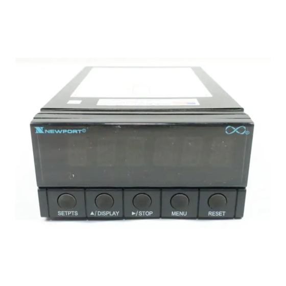
3. Front and Rear Features 3.1 FRONT-PANEL DISPLAYS AND BUTTONS Refer to Figure 3-1 as you read about front panel displays and buttons. Front and Rear Features Figure 3-1. Front Panel TABLE 3-1. FRONT-PANEL DISPLAYS AND BUTTONS FRONT-PANEL BUTTON OR ITEM FEATURE DESCRIPTION/FUNCTION 6-Digit Display... - Page 42 continued from previous page FRONT-PANEL BUTTON OR ITEM FEATURE DESCRIPTION/FUNCTION L /DISPLAY Two-Function button: In Run Mode, Button sequences the display through mode- associated measurements; in Configura- tion and Setpoint Modes, sequences Front and Rear through possible digit and numerical Features settings •...
-
Page 43: Rear Connectors
continued from previous page FRONT-PANEL BUTTON OR ITEM FEATURE DESCRIPTION/FUNCTION • In configuration mode, advances the flashing digit one place to the right, making the new digit accessible for resetting by the L/DISPLAY button; Front and Rear advances the displayed choice to the Features next choice in sequence MENU Button... - Page 44 Front and Rear Features Figure 3-2. Rear View of the Meter with the 4-Relay and Serial Communications Boards Figure 3-3. Rear View with the BCD, Serial Communications, and Analog Output Boards...
- Page 45 P2/CABLE CONNECTOR ALARM V + INPUT ALARM 1 OUTPUT ALARM 2 OUTPUT RESET-A ALARM 4 OUTPUT ALARM 3 OUTPUT ALARM 5 OUTPUT TWICE LINE FREQ DEBOUNCE ALARM, BATTERY RETURN TEST RX RESET-B Front DIGITAL RETURN TEST TX and Rear HOLD / PRINT REQ PULSE OUTPUT Features GATE INPUT...
- Page 46 continued from previous page CONNECTOR NUMBER DESCRIPTION Input and Excitation connector; 3-socket input plug for unregulated excitation for Basic Meter; low level input and excitation for Isolated Pulse Input Board. Not used with Analog Input Board (test points for factory use only). Front and Rear Features...
-
Page 47: Section 4 Basic Concepts And Approaches To Setup And Configuration
4. Basic Concepts and Approaches to Setup and Configuration Your application and what you need to accomplish will dictate setup and configuration of the meter. This section shows you how the meter works; it contains information that will help you see how your meter can best be connected to peripheral devices, or to resets and alarms. -
Page 48: Using Scale Factors
When any mode-associated measurement (except TIME) is on the display, the corresponding Measurement LED is lit. The first measurement in any mode (RATE, SQ RT, or BATCH) corre- sponds to the top LED. The factory preset operating mode of the meter is Rate. The factory preset Rate units are Hertz–cycles per second–which the meter interprets as pulses per second. -
Page 49: Overflow Values And Exponential Format
reading to 0. It provides a quick way to “wipe out” scale factors and offsets so that they can be reconfigured easily. This feature is enabled by setting configuration choice CF4.8 to 1. (See Section 5.4.2.) 4.6 OVERFLOW VALUES AND EXPONENTIAL FORMAT If your source signal units are Hertz, the meter is counting many pulses every second. -
Page 50: Setpoints
Run Mode is accessed under the following conditions: a. Whenever power is applied to the meter b. When the RESET button is pressed twice in the middle of the Parameter list, (or three times if the display shows a submenu) in Configuration Mode c. - Page 51 1. A specific measurement (such as TOTAL) to which it applies 2. A setpoint value: a specific value that when crossed causes the setpoint to become “active” 3. A directional reference indicating whether the setpoint is active ABOVE or BELOW the setpoint value 4.
-
Page 52: Configuring Setpoints
4.9.2 CONFIGURING SETPOINTS All setpoint assignments except for the setpoint value are configured with parameters CNFG 1 through CNFG 3 (see Section 5). They are set to specific values through the SETPTS button on the front panel. To set any setpoint value from Run Mode, press the SETPTS button. -
Page 53: Setpoint-Only Reset
button two times during configuration. It is also done automatically after the last parameter is viewed and saved in Configuration Mode. A cold reset can also be done through serial communications. Refer to the Serial Communications Manual for additional information. 4.10.3 SETPOINT-ONLY RESET A Setpoint-Only Reset returns the meter to Run Mode after writing new setpoint values in operating memory only. -
Page 54: Reset-B
4.10.4.2 RESET-B RESET-B is activated through P2-11. It does the following: 1. Makes the AVG RT (Average Rate) equal to the latest RATE measurement (starts a new AVG RT period) 2. Unlatches a latched alarm (output) assigned to RATE (Setpoints 3 and 4) 3. -
Page 55: Batch Mode Resets
4.10.5 BATCH MODE RESETS 4.10.5.1 RESET-A RESET-A is activated through the P2-3 pin on the 20-socket ribbon connector at the rear of the Main Board. It can be config- ured to act either on the pulse edge (CF4.1=0) or pulse level (CF4.1=1). -
Page 56: Front-Panel Reset
4.10.5.4 FRONT-PANEL RESET The front-panel reset is activated by pressing the RESET button. It can be disabled by setting the CF4.7 choice to 1. It initiates the actions of RESET-B, or RESET-C, depending upon which measure- ment is displayed. Table 4-4 shows the front-panel reset functions for the BATCH mode. TABLE 4-4. -
Page 57: Counting Up
For instance, you’re baking a batch of pies and you know that the pies must be in the oven for 45 minutes. You have two options: You can count up from 0, and at 45 minutes perform a reset that sets the time back to 0;... -
Page 58: Counting Down
Table 4-5. Interdependent Settings for Counting UP ACTIVE ABOVE CONFIG- URATION MODE VALUE BELOW RESET SETTINGS Batch BATCH 1, 2 Above RESET-A CF1.8=0, meter or 3 (Resets counts UP BATCH to Increments Basic BAT NO Concepts Batch BAT NO 4 Above RESET-B CF2.7=0, meter... - Page 59 The following table shows you interdependent settings for counting down from 50 to 0. The setpoint number in the third column shows which setpoint must be assigned to the associated measurement (BATCH, BAT NO, or TOTAL). In this example, Setpoint 1, 2, or 3 is assigned to the BATCH count.
-
Page 60: An Example Showing Setpoint And Reset Control
4.12 AN EXAMPLE SHOWING SETPOINT AND RESET CONTROL Figure 4-1 shows a setup where setpoints and resets control filling of barrels on a conveyor belt. The signal source is a flow meter with a 4-20-mA signal. The flow is directed toward two valves, a “fast”... - Page 61 Here are the system connections and settings: Mode: Rate Setpoint 1: Value, 53; assigned to TOTAL, active ABOVE; enables closing of fast valve Setpoint 2: Value, 55: assigned to TOTAL, active ABOVE; enables closing of slow valve and moving of conveyor belt Basic Concepts...
-
Page 62: Parameters, Choices, And Settings
5. Configuring the Meter Configuration is the process of telling the meter exactly how you would like it to operate. The meter must be ON to configure it. When power is applied, the meter starts to function immediately in Run Mode. To access Configuration Mode, simply press the MENU button. -
Page 63: The Basics Of Configuration
5.2 THE BASICS OF CONFIGURATION The following is a brief outline for configuring the meter: 1. To access any parameter, press the MENU button repeatedly until the desired parameter appears. 2. Press the /STOP button repeatedly until the desired choice appears. -
Page 64: Lockouts
continued from previous page PARA- RATE SQ RT BATCH METER MODE MODE MODE TOT OF TOT OF TOT SC TOT SC TOT SC AL TI AL TI AL TI BAUD GATE T BAUD SER.CNF BAUD SER.CNF DAT FT SER.CNF DAT FT BUS FT DAT FT BUS FT... -
Page 65: Lockouts And Corresponding Actions
5.3.1 LOCKOUTS AND CORRESPONDING ACTIONS Table 5-2 shows you each Lockout and the parameters or functions it controls. The factory preset for all Lockouts is 0. Factory presets are asterisked. TABLE 5-2. LOCKOUTS AND CORRESPONDING ACTIONS PARA- ENABLES/ METER METER CHOICE SETTING DISABLES FUNCTION L1 CNF L1C.1 Enables... - Page 66 Table 5-2 (cont’d PARA- ENABLES/ METER METER CHOICE SETTING DISABLES FUNCTION L1C.8 Enables Display and setting of Disables AVG.CNF parameter (Filter configuration) in Rate and Sq Rt Modes L2 CNF L2C.1 Enables Display and setting of Disables IN.SC.OF parameter (Input Scale and Offset configuration) Configuring L2C.2...
- Page 67 Table 5-2 (cont’d PARA- ENABLES/ METER METER CHOICE SETTING DISABLES FUNCTION L2C.8 Enables Display and setting of Disables GATE T parameter (Gate Time configuration) in Rate Mode only L3 CNF L3C.1 Enables Display of RATE, SQ Disables RT, and BATCH using the LDISPLAY button in Run Mode Configuring...
-
Page 68: Setting Lockouts
5.3.2 SETTING LOCKOUTS The following instructions show you how to set the Lockouts. 1. Press the MENU button repeatedly until L1 CNF appears on the display. (If you are in Run Mode you will need to press the MENU button only once.) NOTE: If L1 CNF, L2 CNF, and L3 CNF do not appear on the display, the S1-A jumper has been removed from the Main Board. -
Page 69: Removing The S1-A Jumper For Added Security
5.3.3 REMOVING THE S1-A JUMPER FOR ADDED SECURITY As an added measure of security after configuration and setting certain lockouts, you may also remove the S1-A jumper on the Main Board. This prevents the Lockouts themselves from appear- ing during configuration and gives you the utmost security in safeguarding settings. - Page 70 Table 5-3 shows configuration parameters CNFG 1 through CNFG 4. Factory preset values are asterisked. TABLE 5-3. CONFIGURATION PARAMETERS CNFG 1 THROUGH CNFG 4 RESULTING ACTION RATE SQ RT BATCH PARAM CHOICE SETTING MODE MODE MODE CNFG 1 CF1.1 SP 1 output is normally SP 1 output is CLOSED;...
- Page 71 continued from previous page RESULTING ACTION RATE SQ RT BATCH PARAM CHOICE SETTING MODE MODE MODE CF1.4 SP 4 is normally OPEN; SP 4 is normally SP4 is assigned to RATE OPEN; SP 4 is if CF1.8=0; SP 4 used for assigned to TOTAL AVG RT if CF1.8=1 if CF1.7=0;...
- Page 72 continued from previous page RESULTING ACTION RATE SQ RT BATCH PARAM CHOICE SETTING MODE MODE MODE CF2.4 SP 4 output is active ABOVE SP 4 value SP 4 output is active BELOW SP 4 value CF2.5 SP 5 output is active ABOVE SP 5 value SP 5 output is active BELOW SP 5 value CF2.6 SP 3 action is not delayed RESET action is...
- Page 73 continued from previous page RESULTING ACTION RATE SQ RT BATCH PARAM CHOICE SETTING MODE MODE MODE CNFG 3 CF3.1 Analog output = disabled (Analog Output) RATE is sent BATCH count is sent AVG RT is sent BAT NO is sent TOTAL is sent Output is ramped (See Appendix K for Ramp Configuring...
- Page 74 continued from previous page RESULTING ACTION RATE SQ RT BATCH PARAM CHOICE SETTING MODE MODE MODE CF3.5 SP 3 output is normal (unlatched) (SP 3) SP 3 output is latched SP 3 output is pulsed with 70 to 140 ms duration unless SP 3 is the designated setpoint in the AL TI parameter, in which case pulse duration is set by AL TI...
- Page 75 continued from previous page RESULTING ACTION RATE SQ RT BATCH PARAM CHOICE SETTING MODE MODE MODE 100 Hz 5% of display input rate full scale cutoff; only cutoff; only input rates input rates reading ≥5% >100 Hz of display full counted scale are counted...
- Page 76 continued from previous page RESULTING ACTION RATE SQ RT BATCH PARAM CHOICE SETTING MODE MODE MODE CNFG 4 CF4.1 External RESET A (P2-3) triggered on pulse edge External RESET A (P2-3) triggered on pulse level CF4.2 Calibrated Analog Output = Voltage Calibrated Analog Output = Current CF4.3 Display HOLD (P2-16) = disabled...
-
Page 77: Avg.cnf (Running Average Configuration) Rate, Sq Rt
continued from previous page RESULTING ACTION RATE SQ RT BATCH PARAM CHOICE SETTING MODE MODE MODE CF4.8 Automatic Scale and Front-panel Offset = disabled STOP =disabled (See below) Automatic Scale and Front-panel Offset = enabled. (Sets STOP =enabled the scale factors of IN.SC.OF and RTE SC to 1.00000, and the Configuring... -
Page 78: In.sc.of (Input Scale And Offset) Rate, Sq Rt, Batch
TABLE 5-4. AVG RT VALUES TOTAL CHOICE VALUES IN AVERAGE AVG.1 AVG.2 AVG.3 AVG.4 Configuring the Meter 1024 2048 4096 8192 16384 32768 The fifth choice, AVG.5, selects the filter type, adaptive or fixed. AVG.5=0 selects the ABC* (Adaptive Bandwidth Control) filter which keeps track of the signal history and detects systematic changes. -
Page 79: Ot.sc.of (Output Scale And Offset) Rate, Sq Rt, Batch
IN.SC.OF can also be used to calibrate both the Isolated Analog Input Board and the incoming signal. See Appendix C for more information and calibration instructions. 5.4.5 OT.SC.OF (Rate, Sq Rt, Batch) OT.SC.OF (Output Scale and Offset) converts the meter reading to the desired analog output signal. - Page 80 Table 5-5 (cont’d) UNTIL DISPLAY DISPLAY STEP PRESS: SHOWS: SHOWS: COMMENTS /STOP 000000. Now enter the display reading of the “low” output signal: Press the L/DISPLAY button repeat- edly to set the flashing digit; press the /STOP button to move to new digits MENU OUTPT 1 /STOP 000000.
-
Page 81: Rte Dp (Rate Decimal Point) Rate, Sq Rt
NOTE: If you receive an error message just after pressing the MENU button for the last time, note the message and see Appendix H. Factory preset settings pertain to current output and are as follows: READ 1 OUT 1 = 4 mA READ 2 = 10000 OUT 2... -
Page 82: Rte Sc (Rate Scale) Rate, Sq Rt
Press the /STOP button; the display will show the current offset; the first digit will flash. Press the L/DISPLAY button to set the flashing digit, and advance to the next one by pressing the /STOP button. When the desired number has been entered, press the MENU button. -
Page 83: Tot Of (Total Offset) Rate, Sq Rt, Batch
setpoints. The meter adjusts the decimal point and continues after displaying an ERR O2. If you receive an ERR O1 message, the placement of the decimal point has left insufficient display places to accommodate the pro- grammed TOT OF value. The meter cannot continue. You must choose a decimal point setting that allows display of all offset digits. -
Page 84: Al Ti (Alarm Time) Rate, Sq Rt, Batch
digit by repeated pressing the L/DISPLAY button, and move to new digits and the decimal point by pressing the /STOP button. (You may move the decimal point to any position here; it is not interdepen- dent with other parameter settings.) Press the MENU button to store TOT SC and advance to the next parameter. -
Page 85: Baud, Ser.cnf, Dat Ft, Bus Ft, Addres, Ser Ti
5.4.14 BAUD, SER.CNF, DAT FT, BUS FT, ADDRES, SER TI (Rate, Sq Rt, Batch) BAUD, SER.CNF, DAT FT, BUS FT, ADDRES, and SER TI are parameters that configure RS-232 and RS-485 board communications. BAUD (RS-232, RS-485) BAUD refers to the data transfer rate through the communications channel linking two or more devices. - Page 86 DAT FT (RS-232, RS-485) DAT FT (Data Format) controls the message response to Point-to- Point Continuous Transmission and V01 commands. It determines whether or not certain characters or values are sent along with the basic message. Factory preset values are asterisked. TABLE 5-7.
- Page 87 BUS FT (RS-232, RS-485) BUS FT (Bus Format) configures the serial communications format. Table 5-8 shows BUS FT settings; factory preset values are asterisked. TABLE 5-8. BUS CONFIGURATION AS SET BY BUS FT RESULTING ACTION RATE SQ RT BATCH PARAM CHOICE SETTING MODE MODE MODE BUS FT BUS.1...
-
Page 88: Set Ti (Set Time) Rate, Sq Rt, Batch
ADDRES (RS-232, RS-485) ADDRES (Address) specifies the meter ID. It is important in RS-485 communications (when multiple meters share the same bus) that each meter have a different address. The address can be from 0 to 199. Press the MENU button repeatedly until the display shows ADDRES, then press the /STOP button. -
Page 89: Bat Dp (Batch Decimal Point) Batch
5.4.16 BAT DP (Batch) BAT DP (Batch Decimal Point) sets the BATCH decimal point position. The factory preset value is RRRRRR. Press the MENU button repeatedly until the display shows BAT DP, then press the /STOP button. The display will show BBBBBB and the current decimal point will flash. -
Page 90: Bat Sc (Batch Scale) Batch
5.4.18 BAT SC (Batch) BAT SC (Batch Scale) is the BATCH scale factor. The factory preset is MULTIP and the factory preset value is 000001. Press the MENU button repeatedly until the display shows BAT SC, then press the /STOP button; the display will flash the current scale, either DIVIDE or MULTIP. -
Page 91: Determining The Rate Scale (Rte Sc)
5.5.1 DETERMINING THE RATE SCALE (RTE SC) TOTAL is not used in a shaft-speed application, no digital commu- nications are used, and the example has no Analog Output. Therefore, many associated parameters will not be used. The first step in this application is to decide what units you want the meter to display. - Page 92 INPUT 1 = 0 READ 1 = 0 INPUT 2 = 100000 READ 2 = 100000 5. Set RTE DP to RRRRR.R (Section 5.4.6). This gives 0.1 RPM resolution. Ignore any ERR 02 message. This indicates a setpoint overflow that can easily be corrected when or if you set setpoints later. 6.
-
Page 93: Step-By-Step Programming Example 2: Linear Flow; Adding Total To Rate With Excitation From The Basic Meter
5.6 STEP-BY-STEP PROGRAMMING EXAMPLE 2: LINEAR FLOW; ADDING TOTAL TO RATE WITH EXCITATION FROM THE BASIC METER In this example, the pulse source is a 100-pulse-per-gallon linear flowmeter (i.e., a turbine meter) which is powered by the unregu- lated 16 V excitation from the Basic Meter. See Figure 5-2. TURBINE Configuring FLOW... -
Page 94: Determining The Total Decimal Point (Tot Dp) And Total Scale (Tot Sc)
Without offset, Desired Reading RTE SC = Actual Input Reading 9999.99 = 0.60000 16667 This is an easy MULTIP scale factor. 5.6.2 DETERMINING THE TOTAL DECIMAL POINT (TOT DP) AND TOTAL SCALE (TOT SC) Selecting the decimal point as TTTTT.T gives a full-tank value of 99,999.9 cubic feet, where each cubic foot = 7.481 gallons. - Page 95 4. Make sure IN.SC.OF is programmed to set the scale to 1 and the offset to 0 (Appendix C). Input the following values: INPUT 1 READ 1 INPUT 2 = 100000 READ 2 = 100000 5. Set RTE DP to RRRR.RR as discussed in Section 5.4.6. Ignore any ERR 02 message.
-
Page 96: Section 6 Operating The Meter
6. Operating the Meter This section contains simple instructions for operating the meter in different modes. Once your meter is configured and power is applied, it will start to operate in Run Mode immediately. Operating it is very simple. 6.1 RATE MODE The meter can display four different measurements in Rate Mode: RATE, AVG RT (Average Rate), TOTAL, and TIME. -
Page 97: Sq Rt Mode
6.2 SQ RT MODE The meter can display four different measurements in Sq Rt Mode: SQ RT, AVG RT (Average Rate), TOTAL, and TIME. 1. To display any one of these measurement values, press the L /DISPLAY button button and wait. The meter will flash the name of the measurement briefly, then display the corresponding value. - Page 98 2. To reset measurement values and associated latched alarms, perform the following resets: a. RESET-A to reset the BATCH count and unlatch BATCH latched alarms b. RESET-B to reset the BAT NO and unlatch BAT NO latched alarms c. RESET-C to reset the TOTAL, unlatch TOTAL latched alarms, and reset TIME as configured by the SET TI value You can also press the front-panel RESET button.
-
Page 99: Appendices
Appendices Basic Meter APPENDIX A BASIC METER: GENERAL INFORMATION, SPECIFICATIONS, JUMPER CONFIGURATION, AND WIRING A.1 GENERAL INFORMATION The Basic Meter is defined as the meter with no optional boards. It accepts input pulses with a low level less than 1 V and a high level greater than 3.5 V from most active sources including TTL or CMOS sources, inactive sources such as open collector outputs and contact closures, and provides unregulated sensor excitation... - Page 100 ENVIRONMENT NORMAL OPERATING TEMP.: 0° to 50°C (32° to 122°F) DERATED OPERATING TEMP.:* 0° to 40°C (32° to 104°F) *When operating at 253V/50Hz Basic Meter and maximum load (4-20mA, 4 alarms on, and 75 mA excitation) STORAGE TEMP.: -40° to 85°C (-40° to 185°F) RELATIVE HUMIDITY: 90% at 40°C (non-condensing) POWER...
- Page 101 3.780 1.890 (96.00) (48.00) 0.812 (20.62) Basic Meter CASE 5.195 (131.95) 5.864 (148.95) SLEEVE PROTECTIVE COVER TOP VIEW SIDE VIEW Figure A-1. Meter Housing A.3 MAIN BOARD JUMPER LOCATIONS AND CONFIGURATION (BEHIND DISPLAY J13 PINS) BOARD SIGNAL CONNECTOR BOARD MAIN BOARD 115 V ac 230 V ac...
- Page 102 Two push-on jumpers and two wired-in jumpers on the Main Board allow the Basic Meter to measure pulses and provide non-isolated Basic Meter excitation. TABLE A-1. MAIN BOARD JUMPERS LOCATION, VIEWING THE BOARD FROM THE JUMPER REAR OF THE METER FUNCTION S1-A On the right, immediately...
- Page 103 16-30 V UNREGULATED EXCITATION Basic Meter (to 75 mA) + TTL/CMOS INPUT PULSES SIGNAL IN COMMON (METER SIGNAL RETURN) Figure A-4. Basic Meter Wiring A.4.1 TTL OR CMOS PULSE SOURCE Input from the pulse source is wired to P3-2 and the common ground to P3-3.
- Page 104 A.4.2 OPEN COLLECTOR OUTPUTS Figure A-6 shows the unregulated meter excitation of a sensor with Basic Meter an NPN transistor output feeding the meter with pulses, going low when the NPN is shut. PNP outputs can also be connected to the meter, but an external pulldown resistor is required to override the internal pullup at the meter’s input.
-
Page 105: Isolated Pulse Input Board: General Information
APPENDIX B ISOLATED PULSE INPUT BOARD: GENERAL INFORMATION, SPECIFICATIONS, JUMPER CONFIGURATION, AND WIRING Isolated Pulse Input B.1 GENERAL INFORMATION Board The Pulse Input Board conditions low-amplitude pulses for both low-level (>20 mV rms) and high-level (up to 230 V rms) input signals. - Page 106 B.3 JUMPER LOCATIONS AND CONFIGURATION Figure B-1 shows the Isolated Pulse Input Board jumper locations. Isolated Pulse Input Board PIN 1 Figure B-1. The Isolated Pulse Input Board Jumpers have the following functions. Factory presets are asterisked: S1-B* Enables 12.6 V Excitation @ 70 mA (See Table B-4) S1-C Enables 5.0 V Excitation @ 50 mA (See Table B-4) S1-A...
- Page 107 High-level signal input (on connector P9-2) threshold levels are as shown in Table B-2 TABLE B-2. ISOLATED PULSE INPUT BOARD: HIGH-LEVEL INPUT THRESHOLDS Isolated Pulse Input Board EXCITATION (V 4.75 11.8 13.3 High 1.40 Threshold (V) 1.65 2.75 0.75 1.25 Threshold (V) 0.95 1.55...
- Page 108 B.4 HIGH-LEVEL PULSE CONDITIONING The board’s high-level input provides a 150 k pullup to the selected excitation voltage (with jumpers configured as shown in Tables B-2 Isolated and B-3). This input is buffered with 90 k series resistance and Pulse Input clamping diodes to ground and excitation so that overscale and/or Board bipolar pulses are readied for the 2/4 V hysteretic pulse detection...
- Page 109 B.7 INPUT WIRING CONNECTIONS WARNING: Do not connect ac power to your meter until you have completed all input and output connections. Failure to do so Isolated may result in injury! This device must only be installed electrically Pulse Input by specially trained electrician with corresponding qualifications.
- Page 110 Isolated Pulse Input Board EXCITATION MAGNETIC PICKUP SIG IN SIG RETURN Figure B-3. Low-level Magnetic Pickup Input to the Isolated Pulse Input Board B.7.2 NAMUR PROXIMITY SENSOR Figure B-4 shows the use of the Pulse Input Board with a NAMUR proximity sensor (less than 1 mA when ON, more than 3 mA when OFF).
- Page 111 B.7.3 NPN TRANSISTOR OR CONTACT-CLOSURE Figure B-5 illustrates the use of the Pulse Input Board with sensor NPN transistor or contact closure output. Contact closures benefit from the debounce filter connection, P9-1 to ground (P3-3). Isolated Pulse Input Board EXCITATION IF NEEDED * FILTER SIG IN...
- Page 112 B.7.4 PNP TRANSISTOR OR CONTACT-CLOSURE Figure B-7 shows the use of the Pulse Input Board with sensor PNP transistor or contact closure to the + excitation supply. Isolated Pulse Input Board * FILTER PULLDOWN EXCITATION PNP OR CONTACT RETURN *Use filter connection for contact closure Figure B-7.
- Page 113 B.7.6 WIRING TABLE Table B-4 shows suggested wiring, jumper configuration, and signal levels for numerous Isolated Pulse Input Board signal sources. Isolated Pulse Input Board TABLE B-4. ISOLATED PULSE INPUT BOARD WIRING JUMPER SIGNAL WIRING CONFIG- SIGNAL LEVEL SOURCE CONFIGURATION URATION LOW/MIN HIGH/MAX...
- Page 114 continued from previous page JUMPER SIGNAL WIRING CONFIG- SIGNAL LEVEL SOURCE CONFIGURATION URATION LOW/MIN HIGH/MAX Isolated Low-Level P3-2, Signal In S1-D, Pulse Input P3-3, Return S1-A for 8.2 V Table B-3 Table B-3 Board Excitation @ 50 mA S1-B for 12.5 V Excitation @ 70 mA S1-C for 5 V...
-
Page 115: Isolated Analog Input Board: General Information
APPENDIX C ISOLATED ANALOG INPUT BOARD: GENERAL INFORMATION, SPECIFICATIONS, JUMPER CONFIGURATION, INPUT CONNECTIONS, AND CALIBRATION C.1 GENERAL INFORMATION Isolated The Isolated Analog Input Board converts voltage ranges from Analog Input Board 400 mV to 10 V and current ranges from 1 mA to 20 mA to a pulse-rate range of 0 to 10 kHz, nominal, providing 354 V of galvanic isolation (IEC spacing) and excitation up to 25 mA. - Page 116 C.3 JUMPER LOCATIONS AND CONFIGURATION Figure C-1. Isolated Table C-1. Isolated Analog Input Analog Input Board Board Range Table RANGE USE JUMPERS 4 - 20 mA S1-B*, S1-C*, S1-E* Isolated Analog Input 0 - 1 mA S1-C, S1-D Board 0 - 400 mV S1-C 0 - 5 V None...
- Page 117 C.4 CURRENT SHUNTS Table C-1 shows that current inputs are accommodated by placing a current shunt to ground with the meter sensitivity on the 400 mV range. (Note: This is accomplished internally via the jumpers.) This low current-loop voltage compliance (low voltage drop) can Isolated be useful if the loop supply has a limited voltage range.
- Page 118 ISOLATED 24 V EXCITATION ANALOG VOLTAGE INPUT SIGNAL IN RETURN RETURN Isolated Analog Input Board (TEST) NC (TEST) NC (TEST) NC Figure C-2. Isolated Analog Input Board Wiring C.8.1 DIFFERENTIAL PRESSURE TO ANALOG INPUT BOARD Figure C-3 illustrates a differential-pressure flow transducer driving the meter via a current-loop transmitter with loop power supplied by the meter.
- Page 119 C.8.2 MULTIPHASE WATTS TRANSDUCER WITH SELF-POWERED TRANSMITTER OUTPUT Figure C-4 shows a multiphase watts transducer with a self-powered transmitter output. The meter can now function as a wattmeter and a watthour meter. Isolated Analog Input Board WATTS TRANSDUCER AC INPUT VOLTAGE SIG IN TRANSMITTER...
- Page 120 INPUT 1 @ 4 mA INPUT 2 @ 20 mA Isolated INPUT 1 @ 0 V Analog Input INPUT 2 @ 5 V Board Figure C-5. Back of the Isolated Analog Input Board Reading from top to bottom, the numbers correspond to the following data: Input 1 @ 4 mA Input 2 @ 20 mA...
- Page 121 Re-write the numbers here so that they are handy when you do the calibration: Input 1 @ 4 mA = Input 2 @ 20 mA = Input 1 @ 0 V = Isolated Analog Input Board Input 2 @ 5 V = The meter must be in the Rate Mode to configure IN.SC.OF.
- Page 122 continued from previous page UNTIL DISPLAY THE WILL DISPLAY PRESS: SHOW: SHOWS: COMMENTS MENU READ 1 Isolated /STOP 000000. Enter the value that you Analog Input would like the just-entered Board INPUT 1 to show on the display. This should be 0 (Hz): Press the L/DISPLAY button repeatedly to set the flashing digit;...
- Page 123 continued from previous page UNTIL DISPLAY THE WILL DISPLAY PRESS: SHOW: SHOWS: COMMENTS Press the L/DISPLAY button repeatedly to set the flashing Isolated digit; press the /STOP Analog Input button to move to new digits Board When you press the MENU button next, the first data point will be saved 10 MENU...
- Page 124 To use the Automatic Scale and Offset feature, set configuration choice CF4.8 equal to 1 (Section 5.4.2.). This sets the scale factors equal to 1 and the offsets equal to 0. Reset the meter by pressing the RESET button two times. At this point, old scale factors and offsets have been “erased.”...
- Page 125 continued from previous page UNTIL DISPLAY THE WILL DISPLAY PRESS: SHOW: SHOWS: COMMENTS MENU INPUT 2 Isolated /STOP 000000. Enter the actual meter reading Analog Input of the “high”input signal Board MENU READ 2 Enter the value that you would like the just-entered INPUT 2 to show on the display.
-
Page 126: Isolated Analog Output Board: General Information, Specifications, Wiring, And Calibration
APPENDIX D ISOLATED ANALOG OUTPUT BOARD: GENERAL INFORMATION, SPECIFICATIONS, WIRING, AND CALIBRATION D.1 GENERAL INFORMATION The Isolated Analog Output Board converts meter output to independently scaled and offset unipolar voltage and/or unipolar current providing 354 V of galvanic isolation (IEC spacing). When the meter is equipped with this board, it can simultaneously Isolated Analog Output... - Page 127 D.3 JUMPER LOCATIONS AND CONFIGURATION The Isolated Analog Output Board has no jumpers. All configura- tion is done via the front panel. D.4 WIRING/CONNECTIONS WARNING: Do not connect ac power to your meter until you have completed all input and output connections. Failure to do so may result in injury! This device must only be installed electrically Isolated by specially trained electrician with corresponding qualifications.
- Page 128 CAL VZ (Calibrate Voltage Zero), CAL VS (Calibrate Voltage Span), CALmAZ (Calibrate milliAmp Zero), CALmAS (Calibrate milliAmp Span). If you recorded them just before installing the board, they are in Section 2.3.3.3. Re-write the numbers here so that they are handy when you do the calibration: CAL VZ = Isolated...
- Page 129 Table D-3 (cont’d) UNTIL DISPLAY THE WILL DISPLAY PRESS: SHOW: SHOWS: COMMENTS MENU CAL VS /STOP XXXXX Input the CAL VS data point. Press the L/DISPLAY button to set the flashing Isolated digit, and the /STOP button Analog Output Board to move on to new digits.
-
Page 130: Isolated Parallel Bcd Output Board: General Information, Specifications, Jumper Configuration, And Wiring
APPENDIX E ISOLATED PARALLEL BCD OUTPUT BOARD: GENERAL INFORMATION, SPECIFICATIONS, JUMPER CONFIGURATION, AND WIRING E.1 GENERAL INFORMATION The Isolated Parallel BCD Output Board produces binary-coded decimal output for direct connection to a printer or to an intelli- gent device such as a PLC (Programmable Logic Controller). E.2 SPECIFICATIONS Isolated Parallel... - Page 131 Table E-1 shows the function of BCD board jumpers. Asterisked jumpers are installed factory presets. TABLE E-1. ISOLATED PARALLEL BCD OUTPUT BOARD JUMPERS JUMPER FUNCTION S1-A Installation brings OVERFLOW signal to P8-U18 S2-A Installation enables 3-digit multiplex; removal enables 6-digit readout S3-A Installation enables 3-digit multiplex or 1-line board address...
- Page 132 U1- - - - - - - - - - - - - - - - - -U20 L1 - - - - - - - - - - - - - - - - - -L20 Figure E-2. End-On View of P8 Table E-2 shows the pin assignments for P8.
- Page 133 E.6 ENABLING TRANSMISSION OF BCD DATA The output configuration of the Isolated Parallel BCD Output Board is controlled by setting CF3.2 (see Section 5.4.2). The setting determines which BCD value is sent. TABLE E-3. ISOLATED PARALLEL BCD OUTPUT BOARD: OUTPUT CONFIGURATION AS SET BY CF3.2 RESULTING ACTION RATE SQ RT...
- Page 134 E.10 THREE-DIGIT-AT-A-TIME MULTIPLEX When jumpers S2-A, S3-A, and S4-A are installed, P8-L20 and S5-C control the times when the upper 3 digits of the 6-digit BCD value appear on the output line (P8-U9 through P8-L14). When jumper S5-C is installed, a LOW level on P8-L20 activates the upper 3 digit outputs;...
- Page 135 If any of these jumpers are removed, the corresponding line must go HIGH or OPEN to assist the board enable; if all four jumpers are removed, for example, the board outputs are enabled ONLY when all four lines are HIGH or OPEN. A ground on any of the four input lines causes the outputs to go to the high impedance state.
-
Page 136: Dual Relay And 4 Relay Output Board: General Information, Specifications, Jumper Configuration, And Wiring
APPENDIX F DUAL RELAY AND 4 RELAY OUTPUT BOARD: GENERAL INFORMATION, SPECIFICATIONS, JUMPER CONFIGURATION, AND WIRING F.1 GENERAL INFORMATION The Dual Relay Output Board and 4 Relay Output Board provides two isolated (354 V per IEC spacing, 500 test), 7-ampere Form-C electro- mechanical relays that enable setpoint-triggered switching to an external device (plus two 1-ampere Form-C electro-mechanical relays for 4 Relay Option). - Page 137 Figure F-2 below show the locations of the 4 Relay Output Board jumpers, the P10 plug connecting the board to the Main Board, and the positions of P6, P7 and P18, the output plugs. Dual Relay Figure F-2. 4 Relay Board Jumpers and Plugs. Output Board Table F-2 shows which jumpers are assigned to each relay.
- Page 138 F.4 WIRING WARNING: Do not connect ac power to your meter until you have completed all input and output connections. Failure to do so may result in injury! This device must only be installed electrically by specially trained electrician with corresponding qualifications. Relay 3 Relay 4 Relay 1 Relay 2...
-
Page 139: G Isolated Rs-232 And Rs-485 Serial Communications Boards
APPENDIX G ISOLATED RS-232 AND RS-485 SERIAL COMMUNICATIONS BOARDS: GENERAL INFORMATION, SPECIFICATIONS G.1 GENERAL INFORMATION The Isolated Serial RS-232 Communications Board provides an isolated digital communications channel between a single meter and another meter or device, or between a single meter and a computer. -
Page 140: Error Messages
APPENDIX H ERROR MESSAGES H.1 FLASHING ERR 01 ERR 01 indicates an OFFSET OVERFLOW. This happens when an offset value is too large to be displayed using the corresponding decimal point position. For example, you enter an offset value of 1000, then program the decimal point 3 places to the left. - Page 141 If you want to change the setpoint value as opposed to changing the decimal position, reprogram the setpoint in the usual manner with the SETPTS button, then adjust the decimal point accordingly. The meter will also flash ERR 02 when the offset value for IN.SC.OF is larger than 38,000.
-
Page 142: Factory Preset Configuration Settings/User Settings
APPENDIX J FACTORY PRESET CONFIGURATION SETTINGS/USER SETTINGS This appendix shows the meter’s factory preset settings. Each parameter contains a blank space or column entitled “User Setting” where you can enter your meter’s actual settings. This is a very helpful reference, especially if you have multiple meters and need to keep track of the operating parameters of each one. - Page 143 ISOLATED PULSE INPUT BOARD JUMPERS PULSE INPUT FACTORY USER BOARD JUMPERS PRESETS FUNCTION SETTING S1-B Installed Enables 12.6 V excitation S1-F Installed Counts pulse on low-to- high transition ISOLATED ANALOG INPUT BOARD JUMPERS ANALOG INPUT FACTORY USER BOARD JUMPERS PRESETS FUNCTION SETTING S1-B...
- Page 144 ISOLATED RS-232 SERIAL COMMUNICATIONS BOARD JUMPERS This board has no jumpers. ISOLATED RS-485 SERIAL COMMUNICATIONS BOARD JUMPERS RS-485 BOARD FACTORY USER JUMPERS PRESETS FUNCTION SETTING S1-B Installed Enables Full Duplex communication SETPOINTS SETPOINT FACTORY PRESET USER SETTING 100. 200. 300. 400.
- Page 145 continued from previous page FACTORY ENABLED USER LOCKOUT CHOICE SETTING METER FUNCTION SETTING L1C.4 Display and setting of CNFG 1 parameter L1C.5 Display and setting of CNFG 2 parameter L1C.6 Display and setting of CNFG 3 parameter L1C.7 Display and setting of CNFG 4 parameter L1C.8 Display and setting of...
- Page 146 continued from previous page FACTORY ENABLED USER LOCKOUT CHOICE SETTING METER FUNCTION SETTING L2C.7 Display and setting of SET TI parameter L2C.8 Display and setting of GATE T parameter L3 CNF L3C.1 Display of RATE, SQ RT, and BATCH through the L/DISPLAY button in Run Mode L3C.2...
- Page 147 MODE Factory preset MODE = Rate (Rate Meter/Totalizer Mode) User Setting = CNFG 1 THROUGH CNFG 4 In the following table, NC means Normally Closed. FACTORY RESULTING ACTION USER PARAM CHOICE SETTING RATE SQ RT BATCH SETTING CNFG 1 CF1.1 SP 1 NC;...
- Page 148 continued from previous page FACTORY RESULTING ACTION USER PARAM CHOICE SETTING RATE SQ RT BATCH SETTING CNFG 2 CF2.1 SP 1 output active ABOVE SP 1 value CF2.2 SP 2 output active ABOVE SP 2 value CF2.3 SP 3 output active ABOVE SP 3 value CF2.4 SP 4 output active ABOVE SP 4...
- Page 149 continued from previous page FACTORY RESULTING ACTION USER PARAM CHOICE SETTING RATE SQ RT BATCH SETTING CF3.5 SP 3 output normal (unlatched) (SP 3) CF3.6 SP 4 output normal (unlatched) (SP 4) CF3.7 SP 5 output normal (unlatched) (SP 5) CF3.8 Cutoff disabled CF3.9...
- Page 150 AVG.CNF (Running Average Configuration) TOTAL TOTAL FACTORY PRESET VALS VALS IN AVERAGE USER SETTING AVERAGE USER AVG.5 factory preset is 0 (ABC - Adaptive Bandwidth Control - Filter) AVG.5 User Setting = IN.SC.OF (Input Scale and Offset) If an Isolated Analog Input Board is ordered as a part of the meter and installed at the factory, IN.SC.OF has no INPUT and READ factory presets;...
- Page 151 RTE DP (Rate Decimal Point) Factory setting is RRRRRR. User Setting = RTE OF (Rate Offset) Factory setting is 0. User Setting = RTE SC (RATE Scale) Factory setting is MULTIP; factory preset value is 000001. User Setting = TOT DP (TOTAL Decimal Point) Factory setting is TTTTTT.
- Page 152 GATE T (Gate Time) Factory setting is 0.30 s. User Setting = BAUD (Data Transfer Rate) Factory setting is 9600. User Setting = SER.CNF (Serial Configuration) SER.CNF FACTORY USER CHOICE SETTING RESULTING ACTION SETTING SER.1 Sets parity bit to ODD SER.2 Sets stop bit to one SER.3...
- Page 153 continued from previous page ENABLED ADDITION TO MESSAGE DAT FT FACTORY RATE SQ RT BATCH USER CHOICE SETTING MODE MODE MODE SETTING DAT.7 AVG RT unit of measure BAT NO unit of measure DAT.8 TOTAL unit of measure BUS FT (Bus Format) RESULTING ACTION BUS FT FACTORY RATE...
- Page 154 SET TI (Set Time) Factory setting is 12:00:00. User Setting = BAT DP (Batch Decimal Point) Factory setting is RRRRRR. User Setting = B LOAD (Batch Load) Factory setting is 0. User Setting = BAT SC (Batch Scale) Factory setting is MULTIP; Factory preset value is 000001. User Setting = CAL VZ, CAL VS, CALmAZ, CALmAS Factory Preset...
-
Page 155: Ramp Specifications
APPENDIX K RAMP SPECIFICATIONS K.1 DEFINITION The ramping function is an output choice for the Isolated Analog Output Board as configured by CF3.1=4. It uses Setpoints 1 and 2 to slowly open and close an electrical valve. The opening interval (the amount of time it takes to completely open the valve) is determined by the AL TI parameter, and the slope of the opening over time is determined by the scale of the OT.SC.OF parameter. - Page 156 99,900 gallons. At this point, the filling valve starts ramping shut, using the negative slope of OT.SC.OF. It stops when it reaches approximately 8% fullscale (about 40 gallons per minute), then closes completely when Setpoint 2 is activated at 100,000 gallons. RESET A SP 1 SP 2...
-
Page 157: Specifications
APPENDIX L SPECIFICATIONS L.1 BASIC METER DISPLAY TYPE: 14-segment, red or green LED DIGIT HEIGHT: 0.54-inch (13.7-mm) DECIMAL POINTS: Six positions, programmable LEADING ZEROS: Blanked OVERRANGE INDICATION: Displayed in exponential format DIMMING: 100% and 50% brightness levels, programmable DISPLAY UPDATE TIME: 0.03 to 3 seconds, programmable INDICATOR LIGHTS: 4 alarms and 3 status modes... - Page 158 MAIN BOARD SETPOINT OUTPUT: 5 open-collector transistors POWER RATING: 150 mA dc @ 1 V sink, 30 V when open GENERAL THRESHOLD: 1 V to 3.5 V PROTECTION LEVEL: 24 V FREQUENCY RANGES: 0.2 Hz to 20 kHz TRIGGER SLOPE: Positive CONNECTION: 3-Socket Input Plug...
- Page 159 L.2 ISOLATED PULSE INPUT BOARD SENSOR EXCITATION: 5 V @ 50 mA (regulated, selectable) 8.2 V @ 50 mA 12.6 V @ 70 mA CONNECTION: 2, 3-socket input plugs INPUT SENSITIVITY LOW LEVEL: 20 mV rms HIGH LEVEL: 2 - 5 V (See Table B-2) MAXIMUM INPUT LOW LEVEL: 60 V rms...
- Page 160 L.4 ISOLATED ANALOG OUTPUT BOARD ±0.05% of FS @ 25˚C ACCURACY: STEP RESPONSE: 10 to 90% full-scale 50 ms TURNDOWN RATIO (OFFSET/SPAN): 100 with 0.01% resolution TEMPCO: 50 ppm/˚C LOOP RESISTANCE: up to 600Ω L.5 ISOLATED PARALLEL BCD OUTPUT BOARD BCD TYPE: Isolated, stored, buffered, addressable, tri-state DIGIT ADDRESSING:...
- Page 161 L.7 ISOLATED RS-232 AND RS-485 SERIAL COMMUNICATIONS RS-232 BAUD RATES: 300, 600, 1200, 2400, 4800, 9600, and 19,200 CONNECTION: RJ-11, 4-wire telephone jack; data in, data out, RTS, GND RECEIVE CAPABILITY: Allows for on-line setup and configuration monitoring and changes TRANSMIT CAPABILITY: Programmable to send RATE, AVG RT, TOTAL, and TIME (with or without units)
- Page 162 Warranty/Disclaimer NEWPORT Electronics, Inc. warrants this unit to be free of defects in materials and workmanship for a period of one (1) year from the date of purchase. In addition to NEWPORT’s standard warranty period, NEWPORT Electronics will extend the warranty period for one (1) additional year if the warranty card enclosed with each instrument is returned to NEWPORT.
- Page 163 TEL: (31) 20 6418405 • FAX: (31) 20 6434643 Toll Free: 0800 0993344 • e-mail: info@newportinc.nl Newport Electronics spol s.r.o. ul. Rude armady 1868 • 733 01 Karvina-Hranice • Czech Republic TEL: 420 (69) 6311899 • FAX: 420 (69) 6311114 Toll Free: 0800-1-666432 •...
Need help?
Do you have a question about the INFINITY INF7 and is the answer not in the manual?
Questions and answers