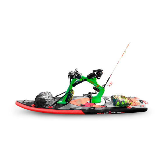
RedShark Bikes ADVENTURE Assembly Instructions Manual
Bike surf
Hide thumbs
Also See for ADVENTURE:
- Assembly instructions manual (36 pages) ,
- Assembly instructions manual (44 pages)

Related Manuals for RedShark Bikes ADVENTURE


Summary of Contents for RedShark Bikes ADVENTURE
- Page 1 BIKE SURF (Personal Water Craft) ASSEMBLY INSTRUCTIONS Unboxing, assembly, warnings & precautions...
- Page 2 VIKTIGT Om du inte förstår något, vänligen kontakta Red Shark Bikes. 重要なことがわからない場合は、RedShark Bikesにお問い合わせください。 Before anything, read user's manuals of this water bike to ensure correct usage through understanding. After reading, store them in a safe place for future reference. Incorrect handling of this product could possibly result in personal injury or physical damage.
- Page 3 MODELS: ADVENTURE model FITNESS model ENJOY model...
- Page 4 ENJOY model...
- Page 5 FITNESS model...
- Page 6 ADVENTURE model...
- Page 7 UNBOXING Open the box at the top and carefully remove all parts from the box. Remove all plastic bags. WARNING: Plastic bags can be dangerous. To avoid any risk of suffocation, keep all bags out of the reach of all babies, children and pets. Do not use in cribs, beds, strollers, or playpens.
- Page 8 PARTS & components ENJOY model 11. SADDLE 5. Seat post CLAM 13. RUDDER 15. Frame CLAM 1. FRAME B 33. SADDLE cover 15. Frame CLAM 16. PEDALS: LEFT & 12. Seat POST RIGHT 18. PROPELLER C 16. PEDALS: CRANK 0. PACKING list (outside the box) 18.
- Page 9 PARTS & components FITNESS model 15. Frame CLAM 13. RUDDER 5. Seat post CLAM 1. FRAME B 16. PEDALS: 11. SADDLE 15. Frame CLAM 16. PEDALS: LEFT & RIGHT CRANK 12. Seat POST 18. PROPELLER D 18. PROPELLER C 18. PROPELLER A 0.
- Page 10 PARTS & components ADVENTURE model 5. Seat post CLAM 13. RUDDER 1. FRAME B 11. SADDLE 15. Frame CLAM 33. SADDLE cover Rear saddle Top frame BAG 16. PEDALS & CRANKS left & right 12. Seat POST 15. Frame CLAM 0.
- Page 11 NUTS, screws and others OPTIONAL: For a permanent frame assembly...
-
Page 12: Board Assembly
ASSEMBLY INSTRUCTIONS BOARD assembly 4.1. Extendthe board... - Page 13 ASSEMBLY INSTRUCTIONS BOARD assembly (Puff up /step 1 from 2) 4.2. Use the AIR PUMP to have only a LITTLE PRESSURE to get the basic shape. Unscrew the cap. Check the position of the valve spout Remove the air pump Puff up the air to 1 psi Insert the air pump...
-
Page 14: Frame Assembly
ASSEMBLY INSTRUCTIONS FRAME assembly CHOSE the frame piece “A”:... - Page 15 ASSEMBLY INSTRUCTIONS FRAME assembly In the FRONT HOLE KEEP ATTENTION: The A & B Holes surface, must be completely clean from dust, sand and other dirty elements. If not it could generate damages on the board skin. Please clean always before. AVOID THE INTERFERENCES from the rudder and propeller with the board surface (holes A and B) if not it could generate damages...
- Page 16 ASSEMBLY INSTRUCTIONS HANDLEBAR assembly: ENJOY & ADVENTURE models. Insert the grips in the handlebar ALCOHOL *not included...
-
Page 17: Handlebar Assembly
ASSEMBLY INSTRUCTIONS HANDLEBAR assembly Insert the handlebar in the STEM TIGHT the 4 screws: TORQUE SPECIFICATIONS: 6 Newtons... - Page 18 ASSEMBLY INSTRUCTIONS HANDLEBAR assembly: FITNESS model. Insert the grips in the handlebar ALCOHOL *not included...
- Page 19 ASSEMBLY INSTRUCTIONS HANDLEBAR assembly: FITNESS model. Insert the handlebar in the STEM TIGHT the 4 screws: TORQUE SPECIFICATIONS: 6 Newtons...
-
Page 20: Rudder Assembly
ASSEMBLY INSTRUCTIONS RUDDER assembly Insert the rudder BAR in to the frame TOP hole 7.2. Pull the ruder post up to the screw BOTTOM hole... - Page 21 ASSEMBLY INSTRUCTIONS RUDDER assembly Line up the handle Insert the rudder post to the STEM bar with the rudder. Enjoy & Adventure Fitness model model Handle Bar Stem Tight the 2 screws ALIGNMENT WITH THE RUDDER bar TORQUE SPECIFICATIONS: W ith the white mark in the center of the stem.
- Page 22 ASSEMBLY INSTRUCTIONS RUDDER assembly Unscrew wing nut RUDDER FUNCTION “T” as transport Chose the position POSITIONS: T: transport • I: level1 • II: Level 2 • III: Level 3 “T”(transport) Screw wing nut TIGHT the wing nut: TORQUE SPECIFICATIONS: 3 Newtons...
- Page 23 ASSEMBLY INSTRUCTIONS FRAME “B” assembly CHOSE the frame piece “B”:...
- Page 24 ASSEMBLY INSTRUCTIONS FRAME “B” assembly TRANSMISSION assembly: Untight the 3 bolts Unify the transmission with the frame...
- Page 25 ASSEMBLY INSTRUCTIONS FRAME “B” assembly Transmission LEVEL assembly: Leave NO space between...
- Page 26 ASSEMBLY INSTRUCTIONS FRAME “B” assembly CHECK the transmission DIRECTION assembly:...
- Page 27 ASSEMBLY INSTRUCTIONS FRAME “B” assembly Transmission ALINGMENT: Align with the white central marked line From top side From TOP side...
- Page 28 ASSEMBLY INSTRUCTIONS FRAME “B” assembly Transmission screws TIGHTEN: TIGHT the 3 bolts: TORQUE SPECIFICATIONS: 6 Newtons Tighten all the 3 screws 8.8. Bolt & Locknut Please use a tool 13 (NOT INCLUDED)
- Page 29 ASSEMBLY INSTRUCTIONS FRAME “B” assembly INSERT the frame in the REAR HOLE with a little air pressure in the board REAR HOLE KEEP ATTENTION: The A & B Holes surface, must be completely clean from dust, sand and other dirty elements. If not it could generate damages on the board skin.
- Page 30 ASSEMBLY INSTRUCTIONS FRAME “C” assembly CHOSE the frame piece “C”:...
- Page 31 ASSEMBLY INSTRUCTIONS FRAME “C” assembly INSERT the frame “C” in to the frame “A” & “B”.
- Page 32 ASSEMBLY INSTRUCTIONS FRAME “C” REAR unión assembly TIGHT the screw through tre two frames with the clamp using the LONGER Allen key (NOT INCLUDED) OPTIONAL: For a permanent chassis fixation...
- Page 33 ASSEMBLY INSTRUCTIONS FRAME assembly (REAR union) ATTENTION! TIGHT the Bolt: FULL POWER TIGHT the bolt STRONGLY TORQUE SPECIFICATIONS: 20 Newtons...
- Page 34 ASSEMBLY INSTRUCTIONS FRAME “C” FRONT unión assembly TIGHT the screw through tre two frames with the clamp using the LONGER Allen key (NOT INCLUDED) OPTIONAL: For a permanent chassis fixation...
- Page 35 ASSEMBLY INSTRUCTIONS FRAME assembly (front union) ATTENTION! TIGHT the Bolt: FULL POWER TIGHT the bolt STRONGLY TORQUE SPECIFICATIONS: 20 Newtons...
- Page 36 ASSEMBLY INSTRUCTIONS FRAME “C” REAR unión assembly TIGHT the screw through to the 5 holes 10 screws 2 plates IGTH side Repeat on the LEFT side...
-
Page 37: Front View
ASSEMBLY INSTRUCTIONS FRAME & BOARD (position) 10.1 Confirm the frame position: Must be in a vertical position (90º towards the board) FRONT view SIDE view 90º 90º 90º... - Page 38 ASSEMBLY INSTRUCTIONS FRAME & BOARD 10.2. PUFF UP the FINAL AIR PRESSURE Pressure: 12 PSi (warm countries) 10.3. Screw the cap onto the valve 13-14 PSi (cold countries)
- Page 39 ASSEMBLY INSTRUCTIONS STRAPS assembly 90º 10.3 Put the chassis upright and tighten the belt Must be in a vertical position (90º towards the board) 1. D-Ring from the board 2. D-Ring from the frame...
-
Page 40: Saddle Assembly
ASSEMBLY INSTRUCTIONS SADDLE assembly 11.1 Untight the bolt, adjust the seat to your 11.2 SADDLE position adjustment (horizontal) position and tight the bolt. HORIZONTAL TORQUE SPECIFICATIONS: 7 Newtons... - Page 41 ASSEMBLY INSTRUCTIONS SADDLE assembly in the frame C 11.3 Open and adjust seat Post CLAMP position 11.4 Check your height 11.5 TIGHT the post clamp 11.6. Check your position 45º Adjustment recommendations...
- Page 42 ASSEMBLY INSTRUCTIONS How to fit CRANKS & transmission 12.4 Remove BOLT and WASHER...
- Page 43 ASSEMBLY INSTRUCTIONS How to fit CRANKS & transmission FRONT IGTH side EFT side 12.4 Insert the crank in to the transmisión axel FRONT IGTH side side REAR REAR...
- Page 44 ASSEMBLY INSTRUCTIONS How to fit CRANKS & transmission 12.5 Screw the bolt with the washer in to the transmisión axel Insert the PEDAL crank Insert the WASHER & BOLT TORQUE SPECIFICATIONS: IMPORTANT 15 Newtons Chek regularly before riding Especially the first rides...
- Page 45 ASSEMBLY INSTRUCTIONS IMPORTANT How to fit PEDALS Chek regularly before riding 12.4 Insert the peddal in to the crank axel EFT pedal IGTH pedal tighten tighten DIRECTION DIRECTION OPOSITE Has a left hand thread Has a normal thread Turn anti-clockwise to tighten Turn clockwise to tighten.
-
Page 46: Propeller Assembly
ASSEMBLY INSTRUCTIONS PROPELLER assembly 13.3 Needle placement 13.1 Remove carefully the plastic protection 13.2. Remove the bold and washer 13.4 PROPELLER placement 13.5 Tight the bolt and the washer TORQUE SPECIFICATIONS: 4 Newtons... -
Page 47: Fin Assembly
ASSEMBLY INSTRUCTIONS FIN assembly 14.1 Insert the fin in the board (bottom rear) slot until the end. Slide the fin onto the bottom side of the board until the end and cross the pin until you hear a click. 14.2 and cross the pin on the hole fin until you hear a click. - Page 48 TRANSPORT & manipulation BE CAREFULL on the below elelements RUDDER: in “T” (HORIZONTAL position) REMOVE the FIN PROPELLER: in HORIZONTAL position Keep the PROPELLER HORIZONTAL POSITION...
- Page 49 TRANSPORT & manipulation NOTE: TROLLEY is extra equipment REMOVE the FIN Trolley BELT...
- Page 50 TRANSPORT & manipulation OPTIONS Most MOST recommended recommended...
- Page 51 ASSEMBLY instructions BEFORE RIDING check MINIMUM 16.2. RUDDER in VERTICAL position 16.1. FIN position DEPTH: 0,6 m...
- Page 52 TO GET ON instructions Before start, PRACTICE THIS ACTIONS until you WEAR LIFE really know, Do it on a calm water with no wind. First JACKET moments are the most stressful ones, From the DEEP water: From the BEACH: SEAT on top of the deck TRANSFER And GO! Pedal...
- Page 53 TO GET ON instructions From a WHARF, boat or similar: Always parallel & from the side PRACTICE THIS ACTION is Grab the handlebar and dangerous, some additional do not transfer the weight support from the wharf it will of your body (from the 2º help you to know how to do it.
- Page 54 AFTER being used Don´t leave it in the water. CLEAN ALWAYS AFTER USED LEAVE IT ALWAYS IN THE WITH FRESH WATER SHADOW If you leave in the water, algae and crustaceans can be hooked, electrolysis may appear, birds droppings and leaf can dirty the parts. Longer sun exposure can damage the units.
-
Page 55: Warnings And Precautions
WARNINGS & PRECAUTIONS WARNING PROHIBITION ATENÇÁO / ADVERTENCIA. ACHTUNG / VAROITUS / PROIBIDO / PROHIBICIÓN / VERBOT. KIELTO / VERBOD / DIVIETI / INTERDICTION / WAARSCHUWING / AVVERTENZA / ATTENTION / ZAKAZ / TILTÁS / FÖRBUD. OSTRZEZENIE / FIGYELMEZTETÉS / VARNIG AIR: 12 -14 psi WEAR DO NOT USE IN... - Page 56 WARNING! Training is required prior to use of this product. You must understand and accept the risks involved before participating in the water bike riding. Always wear an approved Personal Flotation Device NEVER use the Red Shark to go further than you can swim, on your own power. Do not reach into openings, rudder borders or rotating parts.
- Page 57 PRECAUTIONS: Before leaving, always check that the weather forecast is appropriate for this activity. FIRST TIME NOTES: Do it on a calm water with no wind and with the comfort propeller. First moments are the most stressful ones, so you should ride smooth and constantly in a straight line.
Need help?
Do you have a question about the ADVENTURE and is the answer not in the manual?
Questions and answers