
Subscribe to Our Youtube Channel
Related Manuals for Sunrain YC-050TA1


Summary of Contents for Sunrain YC-050TA1
- Page 1 Installation & Operation Manual Swimming Pool Heat Pump Commercial Type Model Number : YC-050TA1 Thank you very much for purchasing our product, please keep and read this manual carefully before you install heat pump. Packing List...
- Page 2 Name Qty. Photos Installation & Operation Manual Wire-controller Heat exchanger connector Wire-controller signal wire Heat Pump Unit - 2 -...
-
Page 3: Table Of Contents
Please keep installation manual properly, and read it carefully before using. The unit must be installed by professional personnel, and install it based on this manual as possible. Special reminding: if the unit would be installed where is vulnerable to lightning stroke, lightning protection measurements must be carried out. -
Page 4: Accessories Description
1. Accessories Description Each unit produced by our factory with the following accessories: Name Qty. Installation & Operation Manual 1 PC Guide users to install the system Wire controller 1 PC Used for the man-machine operation interface Wire controller connecting cable 1 PC Connect wired controller to heat pump unit Heat pump unit... - Page 5 When install the heat pump in a narrow space (equipment room), must keep well ventilated. ● Don't put finger or sticker into the air inlet or air outlet. Because the internal rotor high-speed operation ● may cause injury. When an exception happens (burning smell), turn off the manual power switch immediately, stop ●...
-
Page 6: Heat Pump Unit Working Principle
3. Heat pump unit working principle 3.1 Heat pump working process ● First, the low pressure and superheated gas in the evaporator is inhaled into the compressor then becomes the high temperature and high pressure overheated vapour. ● Second, the overheated vapour is exhausted into the condenser and exchange the heat with the water, then the refrigerant is condensed and becomes the saturated or over cooling high pressure and high temperature refrigerant liquid. -
Page 7: Installation Of The Unit
4. Installation of the unit 4.1 Installation attention ● Avoid installations in such locations with mineral oil. ● Avoid installation in locations where air contains salt or other corrosive gas. ● Avoid installation in locations with serious power supply voltage fluctuation. ●... - Page 8 4.3 Installation space Keep the following indicated space for operation and maintenance first before installation >2000 Unit: mm Figure2 The distance to top barrier >600 Unit: mm >500 >1200 >1200 >500 Unit: mm >600 >500 >1200 >1200 >500 Figure 3 Installation space - 8 -...
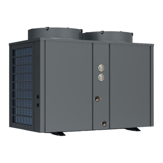
- Page 9 4.4 Heat pump unit size YC-050TA1 Figure 4 Size Size (mm) Model No. YC-050TA1 1410 1000 4.5 Reserve the installation base for the heat pump Please refer to Figure 5. A n c h o r b o lt Anchor bolt...
-
Page 10: Installation Of The Pipeline
installation base. ● Please put shock absorb on base surface. Figure 6 Hoisting diagram 5. Installation of the pipeline 5.1 Attention ● Prevent air, dust and other sundries from going into the water pipes. ● Fix the whole system before install the water pipes. ●... - Page 11 5.2 Instruction 5.2.1 Marginal data 5.2.2 Pipeline installation diagram Figure 8 Diagram I(Single unit for reference) Figure 9 Diagram II(Multiple units for reference) ● The one-way valve is suggested for each unit, to prevent the water back flow. ● The system can be combined with multiple units, but should be controlled by each unit independently. - 11 -...
-
Page 12: Installation Of Optional Accessories
Outlet 63 mm 63 mm YC-050TA1 ● The pipe press and flow rate should be calculated before the diameter selection. ● The hydraulic calculation should be made after the selection of pipe diameter, if the resistance is more than pump head, then need to choose a more power pump, or choose a bigger pipe. -
Page 13: Installation Of Electric Devices
pipe and the adjustable range of the target(see the user manual). And the target sheet can not contact the in-wall of pipe or other throttlers in pipe, or will cause the switch can not reset. Figure 10 Figure 11 7. Installation of electric devices 7.1 Electrical wiring ●... - Page 14 Figure 13 Power cable terminal 7.2 Electrical Wiring Specification Model No. Electrical Wiring Specification YC-050TA1 3*6mm²+2*4mm² 7.3 Circulation pump installation The heat pump only provide the signal for circulation pump, must use an a.c. Contactor to connect the circulation pump.
- Page 15 Figure 15 7.4 Wire controller connection Figure 16 - 15 -...
- Page 16 7.5 Electric wiring diagram Figure 17 - 16 -...
-
Page 17: Instruction Of Operation
8. Instruction of operation 8.1 Control system specifications 8.1.1 Operating condition ● Voltage:100V-265V, 50/60Hz ● Ambient temperature for operation: -30~+60℃ ● Temperature accuracy: ±1℃ 8.1.2 Main function ● Display the storage tank temperature, setting temperature and also check the coil temperature, ambient temperature and exhaust temperature etc. - Page 18 Main control panel (PCB) size 8.1.4 Dial switch Dial1 Dial 2 Dial 3 Dial 4 Unit Master unit Slave unit 1 Slave unit 2 Slave unit 3 Online unit address setting Slave unit 4 Slave unit 5 Slave unit 6 Slave unit 7 Slave unit 8 Dial 5...
- Page 19 8.2 Remote controller and operation 8.2.1 Appearance and button of remote controller Appearance Symbol description Symbol Status Description Constantly bright Heating mode Extinguished Cooling mode Constantly bright Heat pump is OFF Extinguished Heat pump is ON Constantly bright Alarm Constantly bright Defrosting Flashing Defrosting delay...
- Page 20 Display In timing ON period Display In timing OFF period Display water temperature, temperature setting Display 88 88 value, error code Display 88:88 Display the time Display Circulation pump is ON Flashing Turn on circulation pump by manual Display Water feeding valve is ON Display Water return valve is ON Display...
- Page 21 When heat pump is ON, press these two buttons for 3 seconds, forced to defrost When heat pump is ON, press these two buttons for 3 seconds, enable the timing water feed When heat pump is ON, press these two buttons for 3 seconds, enable the timing water return When heat pump is OFF, press these two buttons for 5 seconds, enter into unit address setting interface...
- Page 22 after setting minute, press “ ” button will finish period 1 timing ON setting, and switch to period 1 timing OFF setting, the method is same as above. After period 1 timing ON/OF setting, it will switch to period 2 timing setting and period 3 timing setting, the method is same as above.
- Page 23 Forced turn ON/OFF circulation pump When heat pump is OFF, press “ ”, “ ” and “ ” button for 5 seconds, forced turn ON/OFF circulation pump, when circulation pump is ON, will run for 20 minutes and stop working automatically. Parameter Setting When power on, press “M”...
- Page 24 Enthalpy enhanced 0=OFF;1= ON Measured value valve 2 outlet temp. 4 way valve 2 Compressor 2 current Measured value 4 way valve 3 0=OFF;1= ON Main EEV 2 opening Measured value 4 way valve 4 0=OFF;1= ON Auxiliary EEV 2 opening Measured value By-pass valve 1 0=OFF;1= ON...
- Page 25 When enable the maintenance mode, press “M” button, will display the PCB version information, press “ ” button, will display the wire controller version information. After 3 seconds, back to the data query interface. When turn OFF the heat pump, enable the maintenance mode: Press “...
-
Page 26: Adjusting And Initial Operation
Water pressure switch fault Heating water temp. too high protection Compressor 1 high current protection Compressor 2 high current protection High temp. difference protection(water inlet and outlet) Cooling coil temp. sensor 1 fault Cooling coil temp. sensor 2 fault Low ambient temp. protection Heat recovery heat ex-changer 1 inlet temp. -
Page 27: Operation And Maintenance
and exhaust air inside. ● Do adjustment after electrical safety inspection. ● After the power is switched on, start the test running of heat pump, to see if it can function well. ● Forced operation is forbidden, because it is very dangerous to work without protector. 9.2 Preparation Before Adjustment ●... - Page 28 exchange performance and lead to high electrical consumption, discharge pressure increasing and air suction pressure drop, unit hot water volume produced is less. We can adopt formic acid, citric acid, acetic acid or other organic acid to clean. ● The dirt retention on the surface of evaporator fin should be blew by more than 0.6Mpa compressor air, brushed by fine copper wire, or flushed by high pressurized water, usually one time per month;...
-
Page 29: Fault Analysis And Elimination Method
11. Fault analysis and elimination method - 29 -... -
Page 30: Technical Parameter
12. Technical parameter 12.1 Parameter Model No. YC-050TA1 Power Supply 380V/3/50Hz Heating Capacity(kW) ¹ 49.00 Power Input(kW) ¹ 8.12 COP ¹ 6.04 Heating Capacity(kW) ² 40.80 Power Input(kW) ² 8.34 COP ² 4.89 Cooling Capacity(kW) ³ 36.00 Power Input(kW) ³... - Page 31 After-sale service If your hot water heater can not operate normally, please turn off the unit and cut off the power supply at once, then contact with our service center or technical department.
Need help?
Do you have a question about the YC-050TA1 and is the answer not in the manual?
Questions and answers