Advertisement
Table of Contents
- 1 Table of Contents
- 2 Accessories
- 3 Safety
- 4 Heat Pump Working Principle
- 5 Installation of the Unit
- 6 Installation of the Pipeline
- 7 Installation of Optional Accessories
- 8 Installation and Operation of Electric Devices
- 9 Instruction for Operation
- 10 Initial Operation and Setting
- 11 Operation and Maintenance
- 12 Fault Analysis and Solution Method
- 13 Technical Parameters
- 14 After-Sale Service
- Download this manual
Advertisement
Table of Contents

Related Manuals for Sunrain BYC-007TF1


Summary of Contents for Sunrain BYC-007TF1
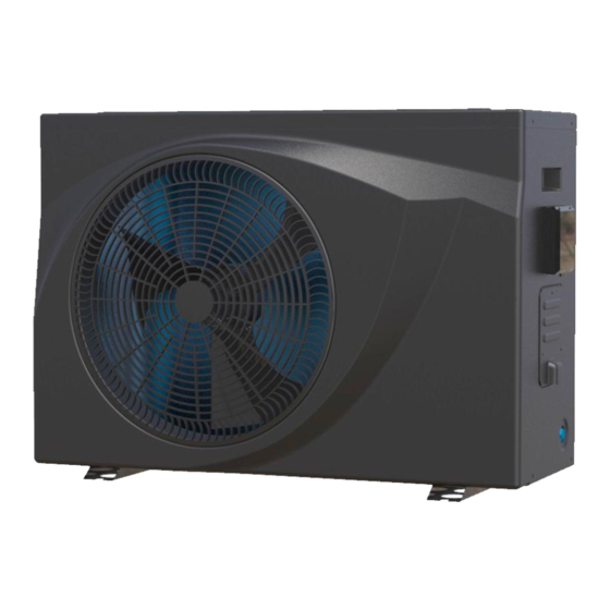
- Page 1 Installation &Operation Manual Full Inverter Swimming Pool Heat Pump MODEL NO. BYC-007TF1 BYC-010TF1 BYC-013TF1 BYC-017TF1 BYC-021TF1 Thank you very much for purchasing our product, please keep and read this manual carefully before you install heat pump.
- Page 3 Packing List Name Qty. Remark Installation &Operation Manual Wire-controller Wire controller box and sponge pad (to be installed on the heat pump shell) Drain-pipe (2 m) Drain-pipe connector Rubber shock absorber Heat Pump Unit (The pipe connector has been installed on the machine) - 3 -...
-
Page 4: Table Of Contents
Please keep installation manual properly, and read it carefully before using. The unit must be installed by professional personnel according to the instructions in this manual. WARNING: if the unit is installed in locations that are at risk of lightning strikes, lightning protection measures must be provided. -
Page 5: Accessories
1. Accessories Each unit produced by our factory comes with the following accessories: Name Qty. Installation & Operation Manual 1 PC User Guide to install the unit Wire controller 1 PC Used for the machine operation interface Drain-pipe 1 PC Used for draining the condensate water Drain-pipe connector 1 PC... -
Page 6: Safety
2. Safety Range of application: 1.Power supply: 220V-240V/1N~50Hz. 2.Ambient temperature: -15°C〜43°C : 3.Working water temperature: Min. inlet water temperature 8°C,Max. outlet Water Temperature 40°C. If the system is always used beyond the available water range, please contact with manufacturer. The installation should be done by the professional persons, to prevent leaking, electric shock or fire. ●... -
Page 7: Heat Pump Working Principle
3. Heat pump unit working principle 3.1 Heat pump operation Heat pumps use heat from the sun by collecting and absorbing energy from the outside air. This energy is then compressed and transferred to the pool water. Your existing water pump circulates the water through the heat pump, which is normally installed next to the pool filtration system, and the water warms up. -
Page 8: Installation Of The Unit
4. Installation of the unit 4.1 Installation Guidelines ● Avoid installations in locations containing mineral oil. ● Avoid installation in locations where the air contains salt or other corrosive gases. ● Avoid installation in locations with serious power supply voltage fluctuation. ●... - Page 9 4.3 Installation space Please observe the space requirements indicated below for optimal operation and maintenance. Figure 2 Horizontal installation space requirements(mm) 4.4 Heat pump dimensions Figure 3 Heat pump dimensions BYC-007TF1 BYC-010TF1 BYC-013TF1 BYC-017TF1 BYC-021TF1 - 9 -...
-
Page 10: Installation Of The Pipeline
4.5 Installation base for heat pump Please refer to Figure 4. A n c h o r b o lt Anchor bolt Screw nut/washer Drainage tray Heat Pump Heat Pump Shock absorb Installation base Drainage tray Concrete Figure 4 Installation base 4.6 Lifting ●Please use four or more soft lifting belts to move the sets(see Figure 5). - Page 11 ● Water inlet and outlet pipes should be protected by an insulation layer. ●Make sure that there is a stable water flow, to prevent excessive throttling. ●Do not handle, move or lift the unit by holding the water inlet and outlet pipe: use only the holes on the beam of the base (see Figure 5) ●...
- Page 12 ●It is recommended to install a one-way valve for each unit to prevent water back flow. ●Multiple units can be installed as part of a system, but each unit should be controlled independently. ●All pipes and valves should be insulated. 5.2.3 Connection sizes Model No. Inlet Outlet BYC-007TF1 BYC-010TF1 BYC-013TF1 DN50 DN50 BYC-017TF1 BYC-021TF1 ●The pipe pressure and flow rate should be calculated before selecting the diameter of the pipe, pressure...
-
Page 13: Installation Of Optional Accessories
6. Installation of optional accessories 6.1 Selection of the water pump ●The circulation pump is required for the system to operate, there is a terminal connection for the pump (single phase) NOTE For single-phase water pumps, please check the wiring diagram. ●Head of circulation pump = height difference between water level and main unit + total pipeline resistance (determined by the hydraulic calculation) + pressure loss of main unit (see nameplate on heat pump). -
Page 14: Installation And Operation Of Electric Devices
●Do not install the units if the power supply specifications are not met. ●After all wiring connections have been completed, check them again carefully before switching on the power. 7.2 Electrical Wiring Specification Model Electrical Wiring Specification BYC-007TF1 BYC-010TF1 3*2.5 mm² BYC-013TF1 BYC-017TF1 3*4.0 mm²... - Page 15 NOTE: If the water pump power is more than 250W, the heat pump will only provide signal control, not direct connection to To water pump power supply, please refer to figure 12 AC 220~50Hz/60hz Maximum 250W Figure 11 Figure 12 7.4 Electric wiring diagram COMP : COMPRESSOR GND : GROUND...
- Page 16 Figure 13 Electrical wiring diagram - 16 -...
-
Page 17: Instruction For Operation
8. Instructions of operating 8.1 Wire controller (Function of buttons) 8.2 Definition of display - 17 -... - Page 18 8.3 Start up & Locking Press the button to switch the heat pump on or off. This button is also used to return to the main interface. When the heat pump is in operation, hold the button for 3 seconds to lock or unlock the controller. (The lock is activated automatically after 60 seconds of inactivity).
- Page 19 : Mode Cooling Inverter: Choose this cooling mode that the heat pump intelligently cools the water of your pool. : Mode Auto: The heat pump can switch Heating and Cooling function automatically 8.5 Set the required temp. On the main interface, press to adjust the desired water temp.
- Page 20 Press again to confirm the setting and return to the main menu. 8.7 Timer setting Hold the button for 3 seconds to enter the setting of Timer ON & Timer Off groups. will flash, then set the Turn On and Off timer like the Clock setting. Pay attention: There are 3 groups Timer for your every day setting.
- Page 21 Press to enter the Running parameters checking, then press to check the below parameters as below: N° Description Unit Ambient temperature °C Evaporator coil temperature °C Exhaust temperature °C Return temperature °C Titanium heat exchanger temperature °C Water inlet temperature °C Water outlet temperature °C...
-
Page 22: Initial Operation And Setting
9. Initial operation and setting 9.1 Attention ●Do adjustment after electrical safety inspection. ●After the power is switched on, start the test running of heat pump, to see if it can function well. ●Forced operation is forbidden, because it is very dangerous to work without protector. 9.2 Preparation Before Adjustment ●Check that the system is installed correctly. -
Page 23: Operation And Maintenance
10. Operation and maintenance 10.1 The heat pump should be installed and operated by qualified professionals. To ensure the continued correct functioning of the system it is recommended that it should be checked and maintenance should be carried out at regular. During maintenance, please pay attention to the points below: ●Check that all parameters are normal during system operation. - Page 24 10.5 Conduct regular maintenance according to the user manual instruction, to make sure the unit running is in good condition. ●If there is a fire, disconnect the power immediately and put the fire out with fire extinguisher. ●The unit’s operating environment should be free of gasoline, ethyl alcohol and other flammable materials to avoid explosions or fire.
-
Page 25: Fault Analysis And Solution Method
11. Fault analysis and solution method - 25 -... -
Page 26: Technical Parameters
12. Technical parameter Model No. BYC-007TF1 BYC-010TF1 BYC-013TF1 BYC-017TF1 BYC-021TF1 Pool Size (indoor) (m³) 35~40 40~50 50~60 75~85 100~120 Pool Size (outdoor) (m³) 15~20 20~30 25~35 35~45 50~60 Heating Capacity(kW) 7.0~1.7 9.5~2.3 12.5~3.0 16.5~3.8 20.2~4.8 Power Input(kW) 1.03~0.11 1.40~0.15 1.84~0.19 2.43~0.24... -
Page 27: After-Sale Service
13. After-sale service If your heat pump does not operate normally, please turn off the unit and cut off the power supply at once, then contact our service center or technical department. - 27 -...
Need help?
Do you have a question about the BYC-007TF1 and is the answer not in the manual?
Questions and answers