Table of Contents
Advertisement
Quick Links
Advertisement
Table of Contents

Related Manuals for InfiNet Wireless R5000


Summary of Contents for InfiNet Wireless R5000
- Page 1 Installation of InfiNet Wireless R5000...
-
Page 2: Table Of Contents
1 Installation Preparations of InfiNet Wireless R5000 ....... . 4... - Page 3 Installation of InfiNet Wireless R5000 Installation of InfiNet Wireless R5000...
-
Page 4: Installation Preparations Of Infinet Wireless R5000
Installation of InfiNet Wireless R5000 1 Installation Preparations of InfiNet Wireless R5000 This section describes all the supplies required to install the InfiNet Wireless R5000 system components and the items included in each installation package. Before the installation, please make sure you have all necessary parts and accessories. -
Page 5: Additional Items Required
Installation of InfiNet Wireless R5000 Component Description Unshielded RJ-45 plug (to be used at end) Quantity depends on the model Shielded RJ-45 plug (to be used at end) 1 pcs RJ-45 plug cap - 1 pcs Cable gland Quantity depends on the... -
Page 6: Tools
Installation of InfiNet Wireless R5000 1.2.2 Tools Screwdrivers set Pliers/Wrenches Spanners set Connectors isolating set: Raw rubber Thermal shrinkage tube Scissors Mantling gun Additional equipment: GPS receiver or area map (with compass and alidade) Big zoom binoculars 1.2.3 Optional Accessories... -
Page 7: Precautionary Measures
Installation of InfiNet Wireless R5000 1.3 Precautionary Measures CAUTION Before you start the installation, please read this section very carefully. Antennas are installed on the roof tops or on the building walls. This work must be accomplished only by personnel having special skills and experience in this area. -
Page 8: Equipment Positioning Guidelines During Infinet Wireless R5000 Installation
For radio planning and path profile analysis, both the terrain model and clutter layer of the area are required. These are typically provided by professional mapping vendors. For details, please contact InfiNet Wireless. Here are some general recommendations for antenna placement:... - Page 9 Installation of InfiNet Wireless R5000 Try to keep the LOS clear of obstructions. In case of installations over vegetation and forest, make sure the direct LOS stays above the trees; in urban environments - above the tallest buildings along the radio path The influence of trees can be variable, depending on seasons (ice, dew, leaves).
-
Page 10: Mounting Types
Installation of InfiNet Wireless R5000 2.2 Mounting Types 2.2.1 Pole Mounting Antenna installation is performed on a special facility called antenna pole. The pole is used for strong antenna tightening at the installation site. Poles might have different modifications depending on the installation requirements. -
Page 11: Installing The Outdoor Units During Infinet Wireless R5000 Installation
Installation of InfiNet Wireless R5000 3 Installing the Outdoor Units during InfiNet Wireless R5000 Installation 3.1 Cable gland assembly during InfiNet Wireless R5000 Installation 3.1.1 Cable gland assembly for R5000-Mmx/Mmxb/Omx /Omxb models. Required components: Unshielded RJ-45 connector Connector cover Shielded RJ-45 connector FTP Cat5e cable;... - Page 12 Installation of InfiNet Wireless R5000 Insert the sealing grommet (6) into the cable gland case (7) as shown on the picture Step 2 Assemble the cable gland as shown on the picture by placing the cable gland nut (8) on...
- Page 13 Installation of InfiNet Wireless R5000 NOTE Do not use the shielded RJ-45 connector on this end of the cable as it should be attached on the IDU end. CAUTION MAKE SURE THAT THE RJ-45 CONNECTOR IS WELL-CRIMPED. A LOOSE CONNECTOR CAN DAMAGE THE DEVICE. PLEASE NOTE THAT SUCH DAMAGE IS NOT COVERED BY THE WARRANTY.
-
Page 14: Cable Gland Assembly For R5000-Smn/Lmn/Smnc Models
Installation of InfiNet Wireless R5000 3.1.2 Cable gland assembly for R5000-Smn/Lmn/Smnc models Required components: FTP Cat5e cable Shielded RJ-45 connector Unshielded RJ-45 connector Cable sealing nut Cable gland case Step 1 Put the cable sealing nut (4) and the cable gland case (5) onto the cable as shown on... - Page 15 Installation of InfiNet Wireless R5000 NOTE The outside diameter value of the FTP Cat5e cable should not exceed 7 mm. NOTE Do not use the shielded RJ-45 connector (2) on this end of the cable as it should be attached on the IDU end.
-
Page 16: Console Cable Connector Soldering Scheme
Installation of InfiNet Wireless R5000 Tighten the sealing nut (4). Do not apply excessive force. 3.1.3 Console cable connector soldering scheme Figure - Console cable connector soldering scheme NOTE A properly assembled cable gland seales against humidity. 3.2 InfiNet Wireless R5000-Omx/Omxb Installation... - Page 17 Installation of InfiNet Wireless R5000 Install and isolate the connectors on the RF cable Determine the FTP cable length that is used to connect IDU and ODU. The total cable length between LAN (behind IDU) and ODU should not be longer than 100 meters.
-
Page 18: Infinet Wireless R5000-Lmn Installation Guidelines
Provide grounding for IDU Connect Ethernet cable to IDU Provide power supply for IDU Connect to the Router using Telnet protocol. CAUTION It is extremely important to install ODU connectors down! 3.3 InfiNet Wireless R5000-Lmn Installation Guidelines Installation of InfiNet Wireless R5000... - Page 19 Installation of InfiNet Wireless R5000 Unpack the equipment Check items integrity Prepare RF-cables of the required length. For 5GHz devices the recommended maximal RF cable length is 1 meter Install and isolate the connectors on the RF cable Determine the FTP cable length that is used to connect IDU and ODU. The total cable length between LAN (behind IDU) and ODU should not be longer than 100 meters.
- Page 20 Installation of InfiNet Wireless R5000 Once the antenna and antenna pole are installed they must be grounded via lightning protection grounding contour. Antenna’s position must be lower than the highest antenna pole point at least by 2 antenna heights. If antenna is NOT DC-shorted (see antenna...
-
Page 21: Guidelines
Installation of InfiNet Wireless R5000 CAUTION It is extremely important to install ODU connectors down! 3.4 InfiNet Wireless R5000-Mmx/Mmxb and R5000-Smn /Smnb/Smnc Installation Guidelines Unpack the equipment Check items integrity Determine the FTP cable length that is used to connect IDU and ODU. The total cable... - Page 22 Installation of InfiNet Wireless R5000 After the FTP cable has been laid, use distribution box to switch from FTP cable to UTP cable with RJ-45 connectors. Service cable connecting IDU and ODU should be FTP Cat5e cable with the outside diameter value not more than 7mm Install ODU on the mounting bracket according to the direction required for the link.
-
Page 23: Grounding And Lightning Protection When Installing Infinet Wireless R5000
Installation of InfiNet Wireless R5000 3.5 Grounding and Lightning Protection when Installing InfiNet Wireless R5000 When installing on poles without lightning protection systems, the ODU or external antenna should be placed on the pole at a height that is at least 1 meter below the top of the pole. In this case, there is a significant probability that the lightning strikes the pole and not the ODU or antenna. -
Page 24: Grounding When Using Aux-Odu-Inj-G
Installation of InfiNet Wireless R5000 Figure - Grounding Connections Schematics when Using IDU-BS-G/IDU-BS-G(60W) 3.5.1 Grounding when using AUX-ODU-INJ-G AUX-ODU-INJ-G is an optional accessory, which may be used to connect third-party DC power sources to the ODU (for example, to power the unit from solar power or wind power sources). - Page 25 Installation of InfiNet Wireless R5000 AUX-ODU-INJ-G Mounting AUX-ODU-INJ-G can be can be installed on a pole, using hose clamps (2). Attach the grounding cable (min cross-section 2.5 mm ) to the case, using grounding bolt (3). Item Name Cable gland...
- Page 26 Installation of InfiNet Wireless R5000 For connection to "ETH IN" terminate the cable with the unshielded RJ-45 connector (4) according to the EIA/TIA-568B For connection to "ETH OUT" terminate the cable with the shielded RJ45 connector (5) according to the EIA/TIA-568B (to provide grounding circuit) For connection to "PWR"...
- Page 27 Installation of InfiNet Wireless R5000 Figure - AUX-ODU-INJ-G power connector Follow requirements: Press on these catchers (1) when the cable is terminated; Use the round cable with diameter from 5mm to 6mm with conductor cross-section from 0.5mm to 2.5mm; FTP Cat5e cable may be used.
-
Page 28: Grounding When Using Aux-Odu-Lpu-G
Installation of InfiNet Wireless R5000 3.5.2 Grounding when using AUX-ODU-LPU-G AUX-ODU-LPU-G is an optional accessory which may be used to serve as a line protection unit for the ODU and for the indoor network equipment connected to the Ethernet port of the IDU. - Page 29 Installation of InfiNet Wireless R5000 AUX-ODU-LPU-G Cable Ggland Assembly In order to ensure that the cable gland remains sealed under any environmental conditions, please, follow the assembly sequence according to the procedure below: 1) Put the cable gland nut (1), the split sealing grommet (2) and the cable gland threaded coupling (3) onto the cable FTP Cat5e.
- Page 30 Installation of InfiNet Wireless R5000 Item Name Cable gland nut Sealing grommet Cable gland threaded coupling Unshielded RJ-45 connector Shielded RJ-45 connector Figure - AUX-ODU-LPU-G Cable Gland Assembly Scheme Installation of InfiNet Wireless R5000...
- Page 31 Installation of InfiNet Wireless R5000 AUX-ODU-LPU-G Grounding Scheme The grounding and lightning protection initial procedures when using AUX-ODU-LPU-G are similar to those when using regular IDU. Figure - AUX-ODU-LPU-G Grounding Scheme For maximum protection of the ODU, IDU and customer LAN devices, use two AUX-ODU-LPU-...
-
Page 32: Grounding When Using Aux-Odu-Sync
Installation of InfiNet Wireless R5000 3.5.3 Grounding when using AUX-ODU-SYNC To connect AUX-ODU-SYNC to the units use the ready-assembled specialized CAB-SYNC cables (must be ordered additionally), which provide interface conversion and lightning protection. AUX-ODU-SYNC Mounting AUX-ODU-SYNC can be installed on a pole, using fasteners from the delivery package: Screw the threaded studs (1) to the unit case. - Page 33 Installation of InfiNet Wireless R5000 Put the cable gland nut (1), the split sealing grommet (2) and the cable gland threaded coupling (3) onto the cable Crimp the connector onto the cable using the crimping tool: CAUTION Make sure that the connector is well-crimped. A loose connector can damage the device.
- Page 34 Installation of InfiNet Wireless R5000 1 - Cable gland nut, 2 - Sealing grommet, 3 - Cable gland threaded coupling, 4 - Unshielded RJ-45 connector, 5 - Cable CAB-SYNC, 6 - Adapter for connection to the console port of the ODU, 7 - Grounding bolt. Figure - AUX-ODU-...
-
Page 35: Antenna Alignment During Infinet Wireless R5000 Installation
Align antennas using optical equipment (binoculars, spyglass) accompanied by mobile phone actions coordination Use GPS receiver, compass and area map Use build-in InfiNet Wireless unit features. These features allow for the evaluation of the current channel and signal quality and are a powerful aid in performing precise antenna alignment. - Page 36 (30-85 mm) wall thick pipe (>85 mm, horizontal/vertical) using additional fasteners (not included to the package) Compatible with all outdoor units produced by InfiNet Wireless RoHS compliant. Figure - MONT-KIT-85 general view MONT-KIT-85 Assembly Scheme Installation of InfiNet Wireless R5000...
- Page 37 Installation of InfiNet Wireless R5000 Figure - MONT-KIT-85 Assembly Scheme MONT-KIT-85 list is bellow Installation of InfiNet Wireless R5000...
- Page 38 Installation of InfiNet Wireless R5000 Item Q-ty Basement Bracket Bracer Lever Bolt M6x14 Bolt M8x35 Bolt M8x80 Nut M8 Washer flat M6 Washer flat M8 Washer spring M6 Washer spring M8 Table - MONT-KIT-85 BOM list MONT-KIT-85 Installation procedure Attach the Basement (PN1) to the back of the device, using Items with PNs 5, 9, 11...
-
Page 39: Possible Variants Of Installation
3.8 InfiNet Wireless R5000-Smn(c) 5-6 GHz, 19 dBi Installation R5000-Smn(c) 5-6 GHz, 19 dBi supports several installation options such as pole mounting using the supplied clamps and pipe/wall/pole mounting using the optional mount kit MONT-KIT- Installation of InfiNet Wireless R5000... -
Page 40: Installation With Clamps
Installation of InfiNet Wireless R5000 3.8.1 Installation with clamps The clamps supplied with each device allow it to be mounted on a 32-60 mm pole. Figure - Mounting with clamps scheme In order to mount the device on a pole follow the procedure below:... -
Page 41: Installation With Mont-Kit-85C
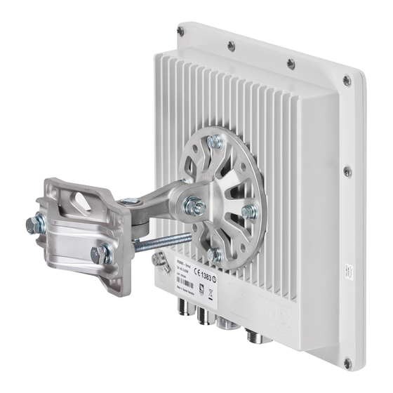
Installation of InfiNet Wireless R5000 3.8.2 Installation with MONT-KIT-85c Use the MONT-KIT-85c kit for a secure and reliable installation to a pipe/wall/pole. This kit allows 2-axis precise alignment under any mounting conditions. Figure - Mounting with MONT-KIT-85c scheme In order to mount using... -
Page 42: Installing The Indoor Units And Infinet Wireless R5000
Figure - Connection Scheme for IDU-BS-G/IDU-CPE and InfiNet Wireless R5000 Connection Scheme for IDU-LA-G(V.01) for second Ethernet port and InfiNet Wireless R5000 Figure - Connection Scheme for IDU-LA-G(V.01) for second Ethernet port and InfiNet Wireless R5000 Installation of InfiNet Wireless R5000... - Page 43 Installation of InfiNet Wireless R5000 Connection Scheme for IDU-LA-G(V.01) (for third-party power sources) and InfiNet Wireless R5000 Figure - Connection Scheme for IDU-LA-G(V.01) for third-party power sources and InfiNet Wireless R5000 Installation of InfiNet Wireless R5000...
Need help?
Do you have a question about the R5000 and is the answer not in the manual?
Questions and answers