
Related Manuals for InfiNet Wireless R5000


Summary of Contents for InfiNet Wireless R5000
- Page 1 InfiNet Wireless R5000 Technical User Manual Revision date: 27 October 2013 Copyright © 2004-2012 by InfiNet Wireless...
- Page 2 Limitation of Liability Infinet Wireless shall not be liable to the purchaser or to any third party, for any loss of profits, loss of use, interruption of business or for any indirect, special, incidental, punitive or consequential damages of any kind, whether arising under breach of contract, tort (including negligence), strict liability or otherwise and whether based on this agreement or otherwise, even if advised of the possibility of such damages.
- Page 3 R5000-Smn model has been designed to operate with the antennas listed below having a maximum gain of 28 dBi. Antennas not included in this list or having a gain greater than specified above are strictly prohibited for use with this device.
-
Page 4: Table Of Contents
II. HARDWARE DESCRIPTION ....................11 1. Power supply units (IDU) ......................11 IDU-CPE ..........................11 Top view ............................. 11 Front panel ............................11 Rear panel ............................12 Connection scheme for IDU-CPE......................12 IDU-BS-G ..........................13 Copyright © 2004-2012 by InfiNet Wireless... - Page 5 Connection scheme for IDU-LA-G (for third-party power sources) ............. 17 2. Outdoor Units (ODU) ......................... 18 InfiNet Wireless Smnb/Smn ....................18 IDU ..............................18 ODU: ..............................18 InfiNet Wireless R5000-Lmn ....................19 IDU ..............................19 ODU ..............................19 InfiNet Wireless R5000-Mmxb/Mmx ..................20 IDU ..............................20 ODU ..............................
- Page 6 Tools to be available at the installation site ................36 2. InfiNet Wireless R5000-Omx/Omxb ................... 37 Installation guidelines ......................37 3. InfiNet Wireless R5000-Lmn ...................... 39 Installation guidelines ......................39 4. InfiNet Wireless R5000-M/Mm and R5000-Smn/Smnb/Smnc ............41 Copyright © 2004-2012 by InfiNet Wireless...
- Page 7 5. Mounting kit (MOUNT-KIT-85) ....................43 General view ........................43 Assembly ..........................45 Possible variants of the installation ..................47 7. InfiNet Wireless R5000-Smnc ..................... 48 II. CONFIGURATION (WEB-INTERFACE) ................. 53 1. Overall functionality overview ....................53 2. Prerequisites ..........................53 3.
- Page 8 2. Device interfaces ........................86 3. Command line interface (CLI) ..................... 87 4. Configuration manipulations ....................... 87 Printing and saving your configuration ................... 87 Import/export ........................88 Uploading firmware ......................88 5. IP address formats ........................88 Copyright © 2004-2012 by InfiNet Wireless...
- Page 9 Load Meter ........................... 98 Acquiring interfaces statistics ....................99 InfiNet Wireless RapidView-1 ....................99 Top view: ............................100 Back view: ............................100 Indicator panel: ..........................101 How to use: ............................101 IV. LOST PASSWORD RECOVERY ................... 104 Copyright © 2004-2012 by InfiNet Wireless...
- Page 10 3. Asymmetrical System Design ....................107 4. «Bad subscriber» problem......................108 VI. SUPPLEMENTARY INFORMATION ................... 109 1. Connectors crimping schemes ....................109 “RJ-45” service cable connector crimping scheme ..............109 Console cable connector soldering scheme ................110 Copyright © 2004-2012 by InfiNet Wireless...
-
Page 11: Getting Started
I. Getting Started This Technical User Manual contains the description of InfiNet Wireless equipment including installation and configuration guidelines, recommendations and troubleshooting sections, supplementary materials. The document is intended to be used by Qualified RF engineers/technicians and IT professionals. Qualified personnel should have skills and experience in the following areas: •... -
Page 12: Supplementary Information
Autobitrate mechanism is an optional powerful feature that provides link reliability in case of changing conditions on the path of the link. The data network built on InfiNet Wireless products is implemented as a routed and switched IP network which reduces flooding and broadcast messages specific to bridged networks and to implementation of Quality-of-Service (QoS) features set. -
Page 13: Abbreviations
5. Additional information Additional information which is not included in this Manual can be found in the following sources: • WANFleX OS User Guide www.infinetwireless.com Our web-site: • http://support.infinetwireless.com • Our support site: Copyright © 2004-2012 by InfiNet Wireless... -
Page 14: Hardware Description
All outdoor equipment is equipped with indoor power supply units. Exact type of IDU which is used with each device model is specified in different models description (see below). I DU-CP E R5000-Smn R5000-Lmn Used with only Top view Front panel Copyright © 2004-2012 by InfiNet Wireless... -
Page 15: Rear Panel
Rear panel Connection scheme for IDU-CPE Copyright © 2004-2012 by InfiNet Wireless... -
Page 16: Idu-Bs-G
I DU-BS-G Top view Front panel *IDU-BS-G model has 10/100/1000BaseT Ethernet port Copyright © 2004-2012 by InfiNet Wireless... -
Page 17: Rear Panel
Rear panel Connection scheme for IDU-BS-G Copyright © 2004-2012 by InfiNet Wireless... -
Page 18: Injector Idu-La-G
2. To connect third-party DC power sources to ODU (for example, to power the unit from solar power or wind power sources). In both cases IDU-LA-G should be properly grounded (please refer to the “Grounding when using IDU-LA-G” section of this manual). Top view Front panel Copyright © 2004-2012 by InfiNet Wireless... -
Page 19: Inside View
Inside view Supported power ratings Model Power rating R5000-Smnb/Smn +9VDC… +56VDC R5000-Lmn R5000-Smnc R5000-Mmxb/Mmx ±43VDC … ±56VDC R5000-Omxb/Omx Copyright © 2004-2012 by InfiNet Wireless... -
Page 20: Connection Scheme For Idu-La-G (For Second Ethernet Port)
WARINING! Exposing unit to the unsupported voltage will result in irreparable damage to the unit! Always observe power requirements! Connection scheme for IDU-LA-G (for second Ethernet port) Connection scheme for IDU-LA-G (for third-party power sources) Copyright © 2004-2012 by InfiNet Wireless... -
Page 21: Outdoor Units (Odu)
2. Outdoor Units (ODU) I nfiNet W ireless Sm nb/ Sm n Default factory option for R5000-Smnb/Smn IDU-CPE Supported power voltage +9…+56VDC ODU: Top view Copyright © 2004-2012 by InfiNet Wireless... -
Page 22: Infinet Wireless R5000-Lmn
I nfiNet W ireless R 5000-Lm n Default factory option for R5000-Lmn IDU-CPE Supported power voltage +9…+56VDC Top view Copyright © 2004-2012 by InfiNet Wireless... - Page 23 I nfiNet W ireless R 5000-M m xb/ M m x Default factory option for R5000-Mmxb/Mmx IDU-BS-G Supported power voltage ±43…±56VDC Front panel Top view Copyright © 2004-2012 by InfiNet Wireless...
- Page 24 Copyright © 2004-2012 by InfiNet Wireless...
- Page 25 I nfiNet W ireless R 5000-Om xb/ Om x Default factory option for R5000-Omxb/Omx IDU-BS-G Supported power voltage ±43…±56VDC Front panel Top view Copyright © 2004-2012 by InfiNet Wireless...
- Page 26 Copyright © 2004-2012 by InfiNet Wireless...
- Page 27 I nfiNet W ireless R 5000-Sm nc Default factory option for R5000-Smnc IDU-CPE Supported power voltage +9…+56VDC Front panel Top view Copyright © 2004-2012 by InfiNet Wireless...
- Page 28 Copyright © 2004-2012 by InfiNet Wireless...
-
Page 29: Odu Led Indicators Description
Radio connection established. The more data is transmitted Blinking through the radio channel the more frequently red indicator is blinking. R5000-Smnc model has a special LED indicator set located at the back of each device designed to provide basic status information. Status Device status... -
Page 30: Installation Procedure
In this respect, it is not recommended to use omni-directional antennas when sector antennas can be used. While planning, it is strongly recommended to consult high-qualified and experienced technicians Copyright © 2004-2012 by InfiNet Wireless... -
Page 31: Antenna Poles Usage
In this case it is of big probability that the lightning strikes the mast and not the antenna. The mast is to be grounded on the grounding contour according to your local standards. When the lightning strikes the antenna, the Copyright © 2004-2012 by InfiNet Wireless... - Page 32 A special attention should be paid if antenna used is not DC-shorted. In this case additional lightning arrestor should be used between the antenna and ODU. Suggested grounding diagram is shown on the picture below. Copyright © 2004-2012 by InfiNet Wireless...
-
Page 33: Grounding When Using Idu-La
(standard) RJ-45 connector. The data & power wires pickups are terminated via IDU protection scheme (discharger and additional air gap). ODU and IDU grounding contours are connected with 100kOhm resistor, and that provides no static charge Copyright © 2004-2012 by InfiNet Wireless... -
Page 34: Antenna Alignment
LOS requirements. General recommendations for antenna alignment are the following: Align antennas using optical equipment (binoculars, spyglass) • accompanied by mobile phone actions coordination • Use GPS receiver and area map Copyright © 2004-2012 by InfiNet Wireless... -
Page 35: Precaution Measures
Use build-in InfiNet Wireless Device features. These features allow • evaluating current channel/signal quality and perform precise antenna alignment Omni-directional and sector antennas have a wide radiation diagram width, thus usually they either do not require a very precise alignment or it is just not necessary due to radio link requirements. -
Page 36: Service Cable Crimping Procedure
R5000-Mmx/Mmxb/Omx/Omxb models. Components required: 1. Standard RJ-45 connector 2. Connector cover 3. Shielded RJ-45 connector 4. STP 5e cable 5. Cable sealing nut 6. Cable sealing bush 7. Cable gland case 8. Cable gland nut Copyright © 2004-2012 by InfiNet Wireless... - Page 37 Make sure that the RJ-45 connector is well-crimped. A loose connector can damage the device. Please note that such damage is not covered by the warranty. Step 3. Attach the cable gland assembly to the device socket. Copyright © 2004-2012 by InfiNet Wireless...
- Page 38 Step 4. Tighten the cable gland nut (8) until you hear a click by rotating it clockwise. Tighten the cable sealing nut (5). Do not apply excessive force. To assemble the R5000-Smn/Lmn/Smnc cable gland follow the instructions below Required components: 1.
- Page 39 Step 2. Insert the connector into the socket until you hear a click. Screw the cable gland case into the port and tighten it. apply excessive force. Step 3. Tighten the sealing nut (4). Do not apply excessive force. Copyright © 2004-2012 by InfiNet Wireless...
-
Page 40: Tools To Be Available At The Installation Site
4. Connectors isolating set • Raw rubber • Thermal shrinkage tube • Scissors • Mantling gun • 5. Additional equipment GPS receiver or area map (with compass and alidade) • Big zoom binoculars • Copyright © 2004-2012 by InfiNet Wireless... -
Page 41: Infinet Wireless R5000-Omx/Omxb
14. Connect RF cable to the antenna. Twist the connector tightly 15. Connect RF cable to the ODU previously having touched RF cable connector case with ODU connector case 16. Isolate RF connectors from both sides (ODU and antenna) Copyright © 2004-2012 by InfiNet Wireless... - Page 42 18. Provide grounding for IDU 19. Connect Ethernet cable to IDU 20. Provide power supply for IDU 21. Connect to the Router using Telnet protocol It is extremely important to install ODU connectors down! Copyright © 2004-2012 by InfiNet Wireless...
-
Page 43: Infinet Wireless R5000-Lmn
RF cable connector case with ODU connector case 15. Isolate RF connectors from both sides (ODU and antenna) 16. Connect the UTP cable to IDU 17. Provide grounding for IDU 18. Connect Ethernet cable to IDU Copyright © 2004-2012 by InfiNet Wireless... - Page 44 19. Provide power supply for IDU 20. Connect to the Device using Telnet protocol It is extremely important to install ODU connectors down! Copyright © 2004-2012 by InfiNet Wireless...
-
Page 45: Infinet Wireless R5000-M/Mm And R5000-Smn/Smnb/Smnc
4. InfiNet Wireless R5000-M/Mm and R5000-Smn/Smnb/Smnc Copyright © 2004-2012 by InfiNet Wireless... -
Page 46: Installation Guidelines
12. Provide grounding for IDU 13. Connect Ethernet cable to IDU 14. Provide power supply for IDU 15. Connect to the Device using Telnet protocol It is extremely important to install ODU connectors down! Copyright © 2004-2012 by InfiNet Wireless... -
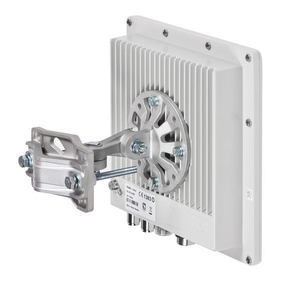
Page 47: Mounting Kit (Mount-Kit-85)
(30-85 mm) o wall o thick pipe (>85 mm, horizontal/vertical) using additional fasteners (not included to the package) • Compatible with all outdoor units produced by InfiNet • RoHS compliant General view Copyright © 2004-2012 by InfiNet Wireless... - Page 48 Copyright © 2004-2012 by InfiNet Wireless...
-
Page 49: Assembly
Assem bly Copyright © 2004-2012 by InfiNet Wireless... - Page 50 Copyright © 2004-2012 by InfiNet Wireless...
-
Page 51: Possible Variants Of The Installation
P ossible variants of the installation Attention! M OUNT-K I T-85 does NOT contain w orm drive hose clam ps or other additional fix tures used in possible variants of installation. Copyright © 2004-2012 by InfiNet Wireless... -
Page 52: Infinet Wireless R5000-Smnc
8. InfiNet Wireless R5000-Smnc R5000-Smnc supports several installation options such as pole mounting using the supplied clamps and pipe/wall/pole mounting using the optional mount kit MOUNT-KIT-85C. The clamps supplied with each device allow it to be mounted on a 32-60 mm pole. - Page 53 • Attach the ground cable (3). If there is a need for further alignment loosen the clamps, adjust the azimuth and tighten them again. Copyright © 2004-2012 by InfiNet Wireless...
- Page 54 Use the MOUNT-KIT-85C kit for a secure and reliable installation to a pipe/wall/pole. This kit allows 2-axis precise alignment under any mounting conditions. Copyright © 2004-2012 by InfiNet Wireless...
- Page 55 Copyright © 2004-2012 by InfiNet Wireless...
- Page 56 (4). • If there is a need for further alignment adjustments loosen the bolts (2) and (4), adjust the unit's position and tighten the bolts again. Copyright © 2004-2012 by InfiNet Wireless...
-
Page 57: Configuration (Web-Interface)
(the default locale will remain unchanged). To make permanent locale changes follow the instructions given in the System Settings paragraph of the Basic Settings section. Copyright © 2004-2012 by InfiNet Wireless... -
Page 58: Basic Settings
WANFleX OS allows temporal configuration changes to be applied by clicking Test. Previous config is automatically restored after a grace period of 180 seconds (3 minutes). The user has options to extend the grace period, or immediately accept/reject the changes. Copyright © 2004-2012 by InfiNet Wireless... -
Page 59: System Settings
SNTP and Time Zone settings: • Start SNTP – starts SNTP service • SNTP IP Address - sets SNTP server IP-address • Time Zone – sets Time Zone. For more details on time zones please visit: http://en.wikipedia.org/wiki/Time_zone. Copyright © 2004-2012 by InfiNet Wireless... -
Page 60: Network Settings
Description field can be used to add a text note to the interface config (up to 72 characters). • rfX Settings - RF interface settings (e.g. rf5.0). Same as the Ethernet settings described above. Copyright © 2004-2012 by InfiNet Wireless... - Page 61 Default Gateway field is used to configure the default gateway used by the unit L3-interfaces to reach hosts on subnets different from its own. Create Pseudo-RF, Create VLAN, Create LAG and Create SVI buttons create the corresponding interfaces in the unit configuration. Copyright © 2004-2012 by InfiNet Wireless...
-
Page 62: Link Settings
DFS only – the DFS system monitors interferences but does not perform radar detection. Please note that in some countries failing to detect public service radar signals is against the regulations and may result in legal action. Copyright © 2004-2012 by InfiNet Wireless... -
Page 63: Static Links
• Security Key – a key word used to encode protocol messages. This key can be up to 64 characters long and should not contain spaces. All units that belong to the same wireless network segment must have the same Security Key. Static Links Copyright © 2004-2012 by InfiNet Wireless... -
Page 64: Mac Switch
• Group# – assigns the switch group identifier (must be unique within the MINT network segment). • Enabled – enables/disables the corresponding switching group. • Add Interface– allows including local network interfaces (ethX, rfX, tunX, etc.) into the switch group. Copyright © 2004-2012 by InfiNet Wireless... - Page 65 • Up/Down arrows – allow users to organize the switch group list. • Remove Group – permanently removes switch group from the unit configuration. The Rules subsection contains the Switch Group rules configured for each group. Copyright © 2004-2012 by InfiNet Wireless...
-
Page 66: Ip Firewall
Up to – used to increase packet priority. The priority will be increased to the specified value only if the processed packet has lower priority. o Set – used to assign new priority regardless of the value already assigned to the packet. Copyright © 2004-2012 by InfiNet Wireless... -
Page 67: Snmp
• Remove Rule – permanently removes the rule from the configuration. • Add Rule – creates a new rule for the current switch group. SNM P All InfiNet Wireless units support SNMP management protocols. This section contains all SNMP-related settings. Access Use the Access subsection to enable SNMP functionality and configure service parameters. - Page 68 • Readonly – this checkbox toggles Write operations restriction for the current user. • Admin – toggles full access to all variables. By default all users have limited access. • Remove User – removes the user from the SNMP configuration. Copyright © 2004-2012 by InfiNet Wireless...
-
Page 69: Traps
SNMP protocol operation requires a network agent instance to send asynchronous messages (traps) whenever a specific event occurs on the controlled device (object). InfiNet Wireless units have a built-in SNMP Traps support module (which acts as an agent) that performs a centralized information delivery from unit internal subsystems to the SNMP server. -
Page 70: Qos Options
Use this section to add CLI-specific commands to the configuration in order to preserve the fine-tuning settings. • Command menu – selects the command to add to the device configuration • Parameters – use this string to specify command parameters and options . Copyright © 2004-2012 by InfiNet Wireless... -
Page 71: Device Status
The “Interface Statistics” section displays the following parameters of all available interfaces of the device: • Interface – the name of the interface MAC Address – the MAC-address of the interface • Status – the status of the interface (Up, Down) • Copyright © 2004-2012 by InfiNet Wireless... - Page 72 The “Auto Refresh” check-box enables automatic statistics update. The update frequency (in seconds) can be set by the “Auto Refresh Time” parameter. The minimal possible value, “0” seconds, makes update process instant. The “Show System Log” button shows the “System Log” section. Copyright © 2004-2012 by InfiNet Wireless...
-
Page 73: Extended Link Diagnostic
Then choose Antenna alignment tool, Performance tests or Graphs from the appeared Extended Link Diagnostics window. Antenna alignment tool Graphical antenna alignment tool visualize antenna alignment process making it quicker, easier and comfortable for the user. Copyright © 2004-2012 by InfiNet Wireless... - Page 74 “Antenna alignment tool” page view for “R5000-Xm” device models is shown below: “Start Test”/”Stop Test” buttons at the bottom of the page start/stop the alignment test. “Exit Test” button returns to the “Device Status” page. “Help” button displays help guidelines for antenna alignment.
- Page 75 Thus it makes possible to observe the “history” of the signal Copyright © 2004-2012 by InfiNet Wireless...
- Page 76 (Input Signal stripes should be located symmetrically relating to the 0 dB value). ALL described recommendations are applicable to both (Local and Remote) sections. Link samples: • Good link sample • Bad link sample Copyright © 2004-2012 by InfiNet Wireless...
-
Page 77: Performance Tests
Performance tests The “Performance tests” page allows performing link throughput tests on all the bitrates that are available for the configured channel bandwidth. “Performance tests” page view is shown below: Copyright © 2004-2012 by InfiNet Wireless... -
Page 78: Stats Graphs
Bi-directional performance test output description for 180 Mbps bitrate (40MHz channel bandwidth): Stats Graphs This tool allows users to monitor device parameters represented as colorful graphical charts. Supported modes are real-time monitoring and daily data logs display. Copyright © 2004-2012 by InfiNet Wireless... - Page 79 Working with the charts: • Select chart region to zoom in. • Hold Shift button and drag the graphs to pan. • Double-click any chart to reset zoom. The parameters set includes: RX/TX Ref. Level (dB) Copyright © 2004-2012 by InfiNet Wireless...
- Page 80 Similar to the previous graphs RX retries are represented by the green lines, TX retries – by the blue lines and link outages – by the red lines. RX/TX Bitrate (Mbps) Copyright © 2004-2012 by InfiNet Wireless...
- Page 81 Link load charts (pps & Kbps) Load charts display actual link load information either in real time of for the given period. Yellow lines represent total link load, green lines – RX load and blue lines – TX load Copyright © 2004-2012 by InfiNet Wireless...
- Page 82 CPU load / System temperature The last chart displays current CPU load and unit temperature (for units equipped with temperature sensors). Copyright © 2004-2012 by InfiNet Wireless...
-
Page 83: Daily Graphs
To access the Extended Interface Statistics tools make a mouse-click on the row with the interface on which you want to get statistics in the “Interface Statistics” section (see the picture below): Copyright © 2004-2012 by InfiNet Wireless... -
Page 84: General Statistics
One can see the number of packets that came to each priority queue and the number of dropped ones. Network Address Table The Network Address Table tool shows the network address table for the interface. Copyright © 2004-2012 by InfiNet Wireless... -
Page 85: Maintenance
“Check Latest Release” and “Check Latest Beta” buttons allow automatic software upgrade. The system checks for updates on the InfiNet Wireless repository and automatically downloads new releases. Note that the unit does not have to have access to the Internet for this feature to work. -
Page 86: Spectrum Analyzer
The following parameters can be set to manage «Spectrum Analyzer» operation: • Unit’s radio interface • Start frequency, determining the initial frequency for scanning in MHz Copyright © 2004-2012 by InfiNet Wireless... - Page 87 Just point a cursor on the needed frequency and you will see a hint with exact Signal level (dBm), Frequency (MHz), Noise Floor (dBm), RSSI (dBm), High RSSI (dBm), Max RSSI (dBm) values. Copyright © 2004-2012 by InfiNet Wireless...
-
Page 88: Dfs
DFS subsystem to rescan those frequencies. If not cleared blocked frequencies will be available for rescan after the time period shown in the right bottom corner of the frequency indicator. “Re-select Channel” button restarts the DFS scanning. Copyright © 2004-2012 by InfiNet Wireless... -
Page 89: Command Line Emulation
CLI. To type the commands use the “Command” field and then press either the “Execute” button on the screen or “Enter” key on your keypad. The commands output are shown in the window above. Copyright © 2004-2012 by InfiNet Wireless... -
Page 90: Configuration (Cli)
(for NAT module, for example); for routes aggregation for RIP protocol. Addresses (subnets) are announced to the network but every packet transmitted through this interface is destroyed eth0 - Ethernet 10/100 Mbit interface • Copyright © 2004-2012 by InfiNet Wireless... -
Page 91: Command Line Interface (Cli)
Example: config show ifc This command will print the interfaces configuration. You can specify several parts of the configuration separating them with a space bar. Example: config show rip nat Copyright © 2004-2012 by InfiNet Wireless... -
Page 92: Import/Export
Optionally, the mask may be specified either by its bit length (the specified number of leading bits in the mask are set to 1, the remaining bits are reset to 0) or numeric value. The IP address 0/0 denotes all possible IP addresses. Copyright © 2004-2012 by InfiNet Wireless... -
Page 93: Ethernet Interface Configuration
– enables burst mode. BURST protocol means grouping several • short packets with the same destination address on a radio link into larger packets, thus cardinally decreasing the response time for applications generating streams of short packets. Burst enabling relates Copyright © 2004-2012 by InfiNet Wireless... -
Page 94: Network Topology Setup
At the core of the system is a MINT (Mesh Interconnection Networking Technology) protocol which acts as a topology defining architecture of InfiNet Wireless system. Please refer to the WANFleX OS User Guide for a detailed description of MINT protocol. Copyright © 2004-2012 by InfiNet Wireless... -
Page 95: Link Setup
R ange| Bitrate calculation Range/Bitrate calculator allows estimation of a bitrate and distance for a particular radio link. This calculator can be downloaded from “Repository” of our support web-site (http://support.infinetwireless.com). Copyright © 2004-2012 by InfiNet Wireless... -
Page 96: Link Diagnostic Tools
Earth surface relief is not taken into account in calculations. 2. Link diagnostic tools Ltest Ltest utility allows precise test of a radio link. It is recommended for antenna alignment when installing a new device or for testing of existing radio link. Copyright © 2004-2012 by InfiNet Wireless... - Page 97 When it is more than 40 it is recommended to lower amplifier power. If maximal signal level is less than 12 it is recommended to lower bitrate or channel width (for example, from 20MHz to 10MHz on the both sides of the radio link). Copyright © 2004-2012 by InfiNet Wireless...
- Page 98 Bandwidth meter is used to test the following radio link characteristics: throughput in kilobits per second, packets per second, number of retries and errors. ltest Use the following « » command options for testing: Copyright © 2004-2012 by InfiNet Wireless...
-
Page 99: Muffer
The scan is performed only for the packets corresponding with the standard of the radio module (802.11a for 5GHz devices and 802.11b for 2.4 GHz devices. Other sources of signals on the scanned frequencies stay unseen. Copyright © 2004-2012 by InfiNet Wireless... -
Page 100: Mac2 Mode
The mac2 regime checks both data packets rfconfig and the link-level ACK messages sent by protocol supported devices. Normal operation of the radio is not possible in this mode. The picture below shows the output mac2 regime. Copyright © 2004-2012 by InfiNet Wireless... -
Page 101: Statistics
Otherwise, it means that a strong interference source appears from time to time breaking your signal Copyright © 2004-2012 by InfiNet Wireless... -
Page 102: Other Modes Of Muffer
By default, the information is displayed on one line and updated every second; the load is measured in kilobytes. Below picture shows the load meter output for the radio interface outputted in line-by-line mode with one second interval. Copyright © 2004-2012 by InfiNet Wireless... -
Page 103: Acquiring Interfaces Statistics
The numbers shown in 4 right columns correspond in physical interface. I nfiNet W ireless R apidView -1 InfiNet Wireless RapidView-1 – is a special diagnostic device that is used for InfiNet Wireless equipment comfort installation, antenna alignment and configuration. -
Page 104: Top View
Top view: Back view: Copyright © 2004-2012 by InfiNet Wireless... -
Page 105: Indicator Panel
Indicator panel: How to use: Turning on: Copyright © 2004-2012 by InfiNet Wireless... - Page 106 1. For turning InfiNet Wireless RapidView-1 on simply push «Power button». 2. Device LEDs will light up for 2 seconds. 3. Device will perform constant tries to connect to ODU. If device’s power is normal Power/ODU connection LED (1) will blink 1 time per second. If device’s power is low LED 1 will blink 4 times per second in turn with not...
- Page 107 Constant lighting — Full Duplex. mode LEDs Not lighting — Half Duplex. IF Ethernet connection is established but corresponding ODU’s interface is not enabled then LEDs 5, 6 indicate connection configuration by blinking 1 time per second. Copyright © 2004-2012 by InfiNet Wireless...
- Page 108 Copyright © 2004-2012 by InfiNet Wireless...
-
Page 109: Lost Password Recovery
1. Locate your device’s serial number (SN) 2. Send this SN to the InfiNet Wireless Technical Support 3. You will be given a special key 4. Enter the device and use SN as a login and received key as a password 5. - Page 110 «ERConsole» utility main window. 4. Send “Serial” and “Sequence” field values to the InfiNet Wireless Technical Support. 5. You will be given a factory password for the device. 6. Press «+» button in the «Scheduled tasks» section of the main window.
- Page 111 “Ok” button. 4. Restart the device. After the restart the “ERConsole” utility will add the IP-address into its Ethernet interface configuration and will up the interface (in case it was configured “down”). Copyright © 2004-2012 by InfiNet Wireless...
- Page 112 Subscriber SNR measured at a base station is significantly worse than that of subscriber side. Increasing transmit bitrate does not influence the overall working • conditions and network performance; • Increasing receive bitrate does worsen noise immunity and network performance. Copyright © 2004-2012 by InfiNet Wireless...
- Page 113 “qm” command). In this case all the packets to “bad subscriber” will be sent after other subscriber stations already get their portions of data. This will result in wireless network performance optimization as subscriber devices’ operation won’t depend on the bitrate of “bad subscriber”. Copyright © 2004-2012 by InfiNet Wireless...
- Page 114 InfiNet Wireless R5000 Technical User Manual ςΙΙ. Supplementary information 1. Connectors crimping schemes “R J-45” service cable connector crim ping schem e Console cable connector soldering schem e Copyright © 2004-2012 by InfiNet Wireless...
- Page 115 InfiNet Wireless R5000 Technical User Manual Copyright © 2004-2012 by InfiNet Wireless...
- Page 116 InfiNet Wireless R5000 Technical User Manual A properly assembled cable gland is sealed against humidity. A properly assembled cable gland is sealed against humidity. Copyright © 2004-2012 by InfiNet Wireless...
Need help?
Do you have a question about the R5000 and is the answer not in the manual?
Questions and answers
how ot do hard reset
To perform a hard reset on an InfiNet Wireless R5000 device using the ERConsole utility:
1. Connect the device and a computer to the same physical Ethernet segment. It is recommended to use a switch between them.
2. Start the ERConsole utility by running the “ERConsole.jar” file on the computer. The utility will enter waiting mode.
3. Restart the device. ERConsole will detect it and display information in the “Discovered devices” section.
4. Send the “Serial” and “Sequence” values shown to InfiNet Wireless Technical Support.
5. After receiving the factory password from Technical Support:
6. Press the «+» button in the «Scheduled tasks» section of ERConsole.
7. In the "New task" window, select “Reset configuration” in the “Command” field.
This process will reset the device configuration.
This answer is automatically generated