
Related Manuals for ITC T-530A


Summary of Contents for ITC T-530A
- Page 1 Ture Diversity MIC System User Manual T-530A/530B/530C Before using the system, please read this manual first...
-
Page 2: Table Of Contents
Index UHF Receiver Module Controls: Features & Indicators………2~6 Handheld Transmitter Controls: Features and Indicators……8~10 Body-Pack Transmitter Controls: Features and Indicators…11~12 How to get the best performance ……………………………13~14 Specifications……………………………………………………14~15... -
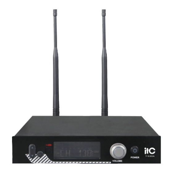
Page 3: Uhf Receiver Module Controls: Features & Indicators
Thank you for purchasing UHF true-single channel wireless Microphone system. Before set up the system, read the manual carefully to understand each part of the system. true Diversity Receiver UHF with 100 frequencies. It is designed for stage, conference room, school, church and many other applications. - Page 4 ③LCD display shows frequency / channel, RF signals, Audio signal Strength, squelch. ④ACT(Automatic Channel Targeting) communication window. To make the easiest and fastest channel set up (pairing) between the transmitter and the receiver. ⑤Function keys:Press the key and hold for 2-3 seconds, then the key is selected, Press “▲▼”...
- Page 5 II. Operation Receiver 1. Make sure that the transmitter is powered off before turning the receiver’ s power on. Press the receiver power key, the LCD will glow and turn on. Then press “ ▲ ▼ ” to choose function and channel, press SET key to confirm the set.
- Page 6 again to confirm it. Use “SET” key to confirm transmitter working status. Press and hold the “▲▼”for a fast forward or backward. When the strength sign shows and the frequency is the same as shown on the transmitter, it means the pairing is done successfully.
- Page 7 B. How to adjust channel (The LCD will display one of the above depends on last status) Press “SET” key for 2-3 seconds, LCD will present, CH 001. Press “◄” or “►” key to change current channel. Press “SET” key to confirm, but the receiver will return to last channel to work after indicator flashes 2-3 seconds if not press “SET”...
- Page 8 E. System lock operation Press “SET” key for 2-3 seconds, LCD will present as the following diagram. After 2-3 seconds, LCD will change to one of the following diagrams. It depends on the last status when LCD was turned off to see what it will show now.
-
Page 9: Handheld Transmitter Controls: Features And Indicators
Handheld transmitter controls: Features and Indicators ⑨ ①Metal windscreen: Hexagonal-shaped to protect the microphone cartridge from being damaged, reducing breath sounds and wind noise. ②LCD display: Indicates channel and remaining battery level. ③IR receiver window ④Power key ⑤RF output power level selector: High (Hi) or Low (Lo) ⑥Lock On/Off switch: If it is set to lock, you cannot change anything from the keys. - Page 10 Operating the handheld microphone The display of handheld transmitter ① ② ① 6-Letter display channel only ② 8-Bar remaining battery level How to use ACT to pair the transmitter and receiver ACT is a short for Automatic Channel Targeting. To make the easiest and fastest channel set up between the transmitter and receiver.
- Page 11 sign shows on the LCD, the pairing is completed and the frequency is set by the system. When the sign shows, it means the pairing failed and you have to do it again as above stated. Repeat the procedure; you will get the pairing done quickly.
-
Page 12: Body-Pack Transmitter Controls: Features And Indicators
Body-Pack transmitter controls: Features and Indicators Top View: Bottom View: ⑴ ⑵ ⑶ BATT + - ⑧ ④ ⑤ ⑨ ⑨ ⑥ ⑦ ⑧ ①Audio Input Jack ②Power switch: When the power switch is turned to ON position, the LED light will flash once, indicating it has a good amount of battery power;... - Page 13 ⑦Battery compartment : Recommend Ni-MH AA batteries×2 or AAX2 rechargeable batteries ⑧Charger port: put body-pack microphone to UCH-09 Charger to charge when LCD shows low battery in body pack LCD. The UCH-09 charger can work with two microphones at the same time. ⑨Volume control: To adjust the sound level of body pack transmitter How to use ACT to pair the body pack and the receiver...
-
Page 14: How To Get The Best Performance
How to get the best performance If you are using more one set of the UHF TD-1, the following channels are recommended to avoid interference among the receiver modules as follows; 1/51 27/77 8/58 34/84 15/65 26/76 7/57 33/83 14/64 40/90 6/56 32/82... -
Page 15: Specifications
Trouble shooting: Some problems and their solutions are identified in the table below. Problem Solution Check for proper connection between LCD not glowing power adaptor and receiver No RF signal Check both transmitter and receiver on receiver channel/frequency correction Check microphone audio cable connected No AF signal body-pack, make sure output cable from on receiver... - Page 16 Frequency Response: 100Hz-15 KHz+/-3dB S/N: >105dB Distortion: <0.5% Operation temperature -10℃~ 40℃ T.H.D: <0.5% (at 10KHz Deviation) Power Supply: DC 12~15V Audio output: Balanced & unbalanced LCD displays: Accumulative working time after battery Replacement, frequency, RF input level, AF level, battery status Muting RF level and wireless channel information.
Need help?
Do you have a question about the T-530A and is the answer not in the manual?
Questions and answers