
Subscribe to Our Youtube Channel
Related Manuals for YoraHome 6550


Summary of Contents for YoraHome 6550
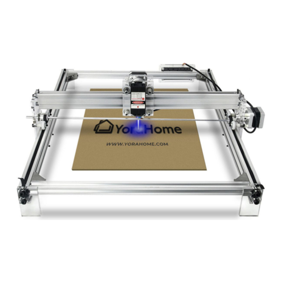
- Page 1 YORAHOME CNC LASER ENGRAVING MACHINE 6550 32-BIT CONTROL BOARD INSTALLATION Version 1.0 • September, 2022...
- Page 2 Purpose This Manual is intended for retrofitting the 32-Bit Control Board to the YoraHome CNC Laser Engraving Machine 6550; replacing the original 8-Bit Control Board. This manual is designed to cover this process only, and is not a complete manual.
- Page 3 Contents Part 1: Packing List Part 2: Assembly Part 2: Default GRBL Settings...
-
Page 4: Part 1 Packing List
Part 1 Packing List Item Size Picture Quantity 32-Bit Control Board Rear Acrylic Mounting Plate 4mm Thickness Front Acrylic Mounting Plate 4mm Thickness... - Page 5 Part 1 Packing List Item Size Picture Quantity USB Cable Cooling Fan 30x30x10 - 12VDC Fan Mounting Pins White Nylon...
- Page 6 Part 1 Packing List Item Size Picture Quantity M3x6 Socket Head Screws M3x8 Socket Head Screws NOTE - Extra hardware is included in this kit; in the event of loss. M3x6x6 Board Standoffs - M/F threads M3x13 Board Standoffs - F/F threads...
- Page 7 Part 2 Assembly Preliminary Steps - For ease of access, position the 6550 with the Control Board facing you. - After setting position; ensure that the Controller is turned off, and the power cord unplugged. - Ensure that your work area has ample room around the machine to allow room to...
- Page 8 Part 2 Assembly Step 1 - Removal of 8-Bit Control Board Disconnect all wire harnesses from the control board: - X Axis Stepper Motor - Y Axis Stepper Motor - Laser (It is recommended that you temporarily label at least one of the stepper motor wire harnesses, to prevent errors on reassembly) NOTE - Photos used in this manual show a...
- Page 9 Part 2 Assembly Step 1 - Removal of 8-Bit Control Board Using the appropriate hex key (included with your original machine purchase), remove the 4 screws holding the Front Acrylic Plate over the control board. Remove the brass standoffs which are retaining the control board to the Rear Acrylic Plate, and remove the control board.
- Page 10 Part 2 Assembly Step 1 - Removal of 8-Bit Control Board Remove the 2 screws holding the Rear Acrylic Plate to the machine frame. KEEP THESE 2 SCREWS AND T-NUTS FOR INSTALLATION OF THE NEW CONTROL BOARD. We recommend retaining the original control board and all associated mounting hardware, as a reserve/spare part.
- Page 11 Part 2 Assembly Step 2 - Preparation of 32-Bit Control Board Carefully remove the protective paper covering from the Front Acrylic Mounting Plate and Rear Acrylic Mounting Plate. Careful use of a small flat screwdriver or knife may help with removal of the protective paper.
- Page 12 Part 2 Assembly Step 2 - Preparation of 32-Bit Control Board Using the M3x6 Screws and M3x6x6 Board Standoffs; secure the standoffs to the Rear Acrylic Mounting Plate, as shown. NOTE - Be sure to use the inner-most holes for mounting the standoffs.
- Page 13 Part 2 Assembly Step 2 - Preparation of 32-Bit Control Board Carefully place the new control board on the standoffs, ensuring that there is no part of the bottom of the control board contacting the Rear Acrylic Mounting Plate. Using the M3x13 board standoffs, secure the control board to the Rear Acrylic Mounting Plate.
- Page 14 Part 2 Assembly Step 2 - Preparation of 32-Bit Control Board Using the M3x8 screws, secure the Front Acrylic Mounting Plate over the control board. Ensure that the hole in the Front Acrylic Mounting Plate is properly positioned to allow access to the control board power switch.
- Page 15 Part 2 Assembly Step 2 - Preparation of 32-Bit Control Board Position the Cooling Fan over the opening in the Front Acrylic Mounting Plate. NOTE - Ensure the fan is installed with the support frame facing out, as shown, and that the wire harness can reach the connection on the Control Board.
- Page 16 Part 2 Assembly Step 2 - Preparation of 32-Bit Control Board Plug the Cooling Fan wire harness into the provided connector on the Control Board.
- Page 17 Part 2 Assembly Step 3 - Install Control Board to Machine Frame Using the 2 Screws and T-Nuts removed in Step 1 ; mount the (3/3) new Control Board assembly to the Machine Frame as shown.
- Page 18 Part 2 Assembly Step 4 - Wiring Connections Laser X Axis Y Axis Connect the wire harnesses to the respective ports on the Control Board, as shown. - X Axis Stepper Motor - Y Axis Stepper Motor - Laser The remaining connectors on the control board will not be used at this Power time.
- Page 19 Part 3 Default GRBL Settings $100=80.500 (X-axis travel resolution) $0=3 (Step pulse time) $101=80.500 (Y-axis travel resolution) $1=254 (Step idle delay) $102=100.000 (Z-axis travel resolution - not used) $2=0 (Step pulse invert) $103=100.000 (A-axis travel resolution - not used) $3=5 (Step direction invert) $104=100.000 (B-axis travel resolution - not used) $4=0 (Invert step enable pin) $105=100.000 (C-axis travel resolution - not used)
- Page 20 https://Facebook.com/groups/YoraHome.CNC...
Need help?
Do you have a question about the 6550 and is the answer not in the manual?
Questions and answers