Table of Contents
Advertisement
Advertisement
Table of Contents

Related Manuals for YoraHome 6550


Summary of Contents for YoraHome 6550
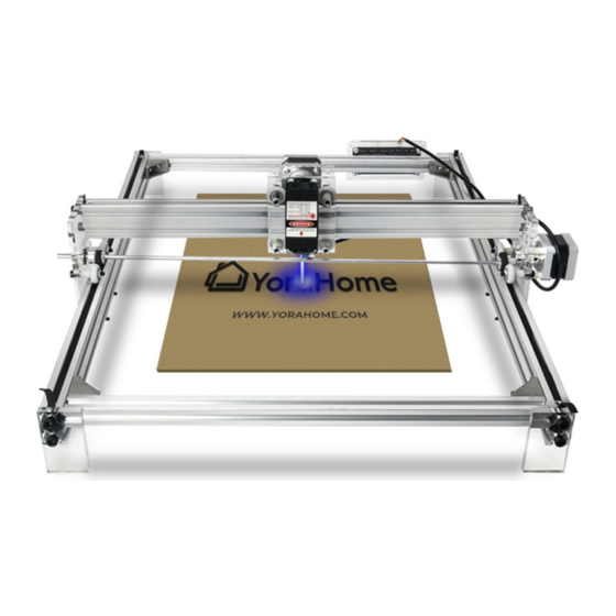
- Page 1 YORA CNC LASER ENGRAVING MACHINE 6550 USER MANUAL Version 2.1 • March, 2021...
- Page 2 Purpose This Manual is intended for assembly of the YoraHome 6550 Laser Engraving Machine. Before beginning assembly, we recommend conducting an inventory using the Packing List to ensure all components are present. NOTE - there may be extra hardware included; this is normal, in case items get dropped or lost.
- Page 3 Contents Part 1: Packing List Part 2: Mechanical Installation Part 3: Software Introduction Part 4: Recommended Settings Part 5: FAQ...
- Page 4 Part 1 Packing List Name Model Parameter Quantity Picture 610 mm Aluminium Profile 740 mm 690 mm Linear Axis 590 mm Corner Connector M6x12 M5x10 M5x45 Bolt M5x30 M3x25 M3x8...
- Page 5 Part 1 Packing List Name Model Parameter Quantity Picture Acrylic Sheet A Acrylic Sheet B Acrylic Sheet C Acrylic Sheet D Acrylic Sheet E Board Mount Plate A Board Mount Plate B...
- Page 6 Part 1 Packing List Name Model Parameter Quantity Picture Stepper Motor Laser Module Synchronous Wheel Guide Wheel Coupling...
- Page 7 Part 1 Packing List Name Model Parameter Quantity Picture Washer T-Slot Nut M5 Threads Square Nut M3 Threads Hex Wrench 2 | 2.5 | 3 | 4 1 of each Copper Coupler M3 Threads M5x12 Nylon Spacer M3x16 Hex Nut Nylon Washer Bearing F685Z...
- Page 8 Part 1 Packing List Name Model Parameter Quantity Picture 710mm Timing Belt 840mm Stepper Motor Cable USB Cable Control Board Power Supply Cable Tie Cable Wrap Safety Glasses...
- Page 9 Part 1 Packing List Name Model Parameter Quantity Picture M3x6mm Brass Standoff M3x17mm T-Nut Phillips Head Screw M4x8mm Cap Screw M3x8mm Cap Screw M3x10mm Hex Nut...
- Page 10 Part 2 Mechanical Installation Step 1 Base Assembly - note the front and rear rails mount inside the side rails Aluminium Profile 610 mm T-Slot Nut Corner Connector Washer Bolt M5x10 690 mm 610 mm...
- Page 11 Part 2 Mechanical Installation Step 2 Acrylic Sheet A Assembly - Left side of machine Acrylic Sheet A Nylon Spacer M5x12 Guide Wheel Hex Nut Bolt M5x30...
- Page 12 Part 2 Mechanical Installation Step 3 Acrylic Sheet B, Coupling - Right side of machine Y-Axis Stepper Motor Assembly Acrylic Sheet B Guide Nylon Bolt Stepper Motor Spacer Wheel M3x25 M3x16 NOTE - Ensure Nylon Spacer there is a gap M5x12 between the Coupling and...
- Page 13 Part 2 Mechanical Installation Step 4 Laser Module, X-Axis Stepper Motor, Acrylic Sheets C and D Assembly 1. Laser Module Assembly 2. X-Axis Stepper Motor 3. Assemble 1. & 2. Laser Acrylic Sheet D Head Acrylic Sheet C Bolt Bolt Synchronous M3x8 M3x8...
- Page 14 Part 2 Mechanical Installation Step 4 Laser Module, X-Axis Stepper Motor, Acrylic Sheets C and D Assembly Stepper Motor Mounting Laser Mounting to Acrylic Sheet D (with 2 M3x10) to Acrylic Sheet C...
- Page 15 Part 2 Mechanical Installation Step 5 Top Rail Assembly Pass the aluminum profile 740mm through the installed laser module. Insert the X-Axis Timing Belt too. Timing Belt 840 mm...
- Page 16 Part 2 Mechanical Installation Step 5 Top Rail Assembly Bolt M3x8 Square...
- Page 17 Part 2 Mechanical Installation Step 6 Top Rail with Linear Axis Assembly Linear Bolt Axis M6x12 Bearing F685Z Nylon Washer Synchronous Wheel...
- Page 18 Part 2 Mechanical Installation Step 6 Top Rail with Linear Axis Assembly Note proper orientation of Synchronous Wheels...
- Page 19 Part 2 Mechanical Installation Step 7 Top Rail Kit with Base Assembly Pass the assembled kit into the base.
- Page 20 Part 2 Mechanical Installation Step 7 Top Rail Kit with Base Assembly Timing Belt 710 mm Bolt M3x8 Square Nut Insert the Timing Belts on both sides of the Y-Axis.
- Page 21 Part 2 Mechanical Installation Step 8 Acrylic Sheets E Assembly - Assemble Acrylic Sheets E to each corner of the frame.
- Page 22 Using the M4 Phillips Head Screws and M4 T-Nuts, attach Acrylic Block A to the outside of the 6550 frame in the right rear corner; same location noted in the manual. Use the lower 2 holes to position the board properly for installation.
- Page 23 Part 2 Controller Board Mounting Step 2 Using the M3x6 Brass Standoffs and the M3x17 Brass Standoffs, attach them to the control board as shown. Ensure that the M3x6 are on the back of the board, and the M3x17 are on the front.
- Page 24 Part 2 Controller Board Mounting Step 3 Using 4 of the M3 Hex Nuts, attach the Control Board to Acrylic Block A.
- Page 25 Part 2 Controller Board Mounting Step 4 Using 4 M3x8 Cap Screws, attach Acrylic Block B to the front of the Control Board.
- Page 26 Part 2 Controller Board Wiring Connect the X and Y stepper motor wire harnesses, and the laser module harness to the control board as shown. NOTE - See next section for proper laser harness selection.
- Page 27 Part 2 Laser Installation Connect the laser module to the controller board using the provided harness (encased in a black plastic sheath). Do NOT use the other 3-wire harness with exposed conductors (red/white/black); this will cause the laser to not operate properly!
- Page 28 Part 2 Laser Installation Note that the ideal focal length for the lasers differs, depending on the laser power. See below for correct distance from laser lens to workpiece. Metal cylinder (20mm height) to set the distance for fixed lens 3.5W and 5.5W (adjustable lens) Focal length = 45mm 15W and 40W (fixed lens)
- Page 29 NOTE FOR MAC USERS: If your Mac is running Mojave OS or higher, do NOT install the driver, as the OS has native support for the CH340. If you are running Sierra or High Sierra, please contact YoraHome Technical Support for additional guidance.
- Page 30 Part 3 Software Introduction Determine your machine COM’s port • Windows XP: Right click on My Computer, select Manage, then Device Manager. • Windows 7: Click on Start on the taskbar, right click on Computer, select Manage, then Device Manager. •...
- Page 31 Part 3 Software Introduction Install Your Laser Engraving Software LaserGRBL is one of the best Windows GCode streamers for DIY Laser Engravers. LaserGRBL is able to load and stream GCode path to your control board, as well engrave images, pictures and logos with internal conversion tool.
- Page 32 Part 3 Software Introduction - LaserGRBL Open the LaserGRBL Select the desired COM Software port, then click the “Connect” icon...
- Page 33 Part 3 Software Introduction - LaserGRBL Test your machine for proper motion control If the connection is using the “Jog” buttons - if the Y axis is successful, you will see the reversed, switch the motor cable to the other message below in the white port on the control board.
- Page 34 Part 3 Software Introduction - LaserGRBL If your machine is equipped with either the 3.5W or 5.5W lasers, the lens must be focused at the appropriate focal height of 45mm. Click the “Focus” button at the bottom of the program window to turn the laser on at low power for focusing, click again to turn the laser off.
- Page 35 Part 3 Software Introduction - LaserGRBL To load an image for engraving, click on the “File” menu, then select “Open File”. In the Windows Explorer window; navigate to the desired image file on your computer. Common file types are JPG, BMP, PNG, SVG.
- Page 36 Part 3 Software Introduction - LaserGRBL Parameters default, click next You can use the default settings or adjust them - see our tutorial videos in the Facebook Users Group for additional information.
- Page 37 Part 3 Software Introduction - LaserGRBL The engraving speed and MIN/MAX settings will need to be adjusted to meet the material being engraved. Note that the size values will automatically update whenever one is changed in order to maintain the aspect ratio of the origin image. Then click the “Create”...
- Page 38 Part 3 Software Introduction - LaserGRBL Using the jog buttons, position the laser to the lower left corner of the desired burn location; then click the “Globe” button to set the origin. Then click the “Play” button to start the laser engraving process.
- Page 39 Part 3 Software Introduction - Lightburn In the lower right of the screen, in the “Laser” pane, Open the Lightburn click on “Devices” Software...
- Page 40 Part 3 Software Introduction - Lightburn The “New Device Wizard” will start - select In the Devices dialog box, the “GRBL” option, and click “Next” click on the “Create Manually” button.
- Page 41 Part 3 Software Introduction - Lightburn If you would like to name the machine, you The default connection may do so here. Set the work area dimensions method should be as shown - X=650; Y=500 - click “Next”. “Serial/USB” - click “Next”.
- Page 42 Software Introduction - Lightburn Set the origin for your laser - on the Confirm your settings, then click “Finish” 6550, that is the Front Left. Ensure the to return to the Devices screen. Auto “Home” option is off; otherwise errors will occur - click “Next”.
- Page 43 Part 3 Software Introduction - Lightburn Click on “OK” to return to the main Lightburn screen.
- Page 44 Part 3 Software Introduction - Lightburn Click on the “File” menu, then select “Import” to open an image file.In the Windows Explorer window; navigate to the desired image file on your computer. Common file types are JPG, BMP, PNG, SVG.
- Page 45 Part 3 Software Introduction - Lightburn To set the engraving parameters, select the image on the grid, then go to the “Cuts/Layers” tab in the upper right pane (see next page for detail).
- Page 46 Part 3 Software Introduction - Lightburn Select your imported image, then select the parameters for your engraving - in the example below, we have selected a engraving speed of 1000 mm/min, at a power of 60%; with the mode set to “Fill”. This will direct the machine to burn the entire image and fill in the shape.
- Page 47 Part 3 Software Introduction - Lightburn Select the “Move” tab, and use the jog buttons to position your laser at the lower left corner of where the design is to be burned. Click on the “Set Origin” button to set the start position.
- Page 48 Part 3 Software Introduction - Lightburn Use the Power setting and the “Fire” button to turn the laser on at low power for focusing, click again to turn the laser off. If the “Fire” button is not visible, go to the Device Settings on the “Edit”...
- Page 49 Part 3 Software Introduction - Lightburn Finally, click on the “Start” button in the Laser pane to start the laser engraving process.
- Page 50 Key GRBL Settings Intro The Yora 6550 motherboard has a series of settings on it that allow your machine to work correctly. Some may be wrong (which shouldn’t be the case), so you may have to adjust them to take a full advantage of your machine.
- Page 51 Part 4 Recommended Settings Key GRBL Settings $3 - Direction port invert mask If an axis is moving in the wrong direction, you need to change one of the settings, namely $3, the direction port invert mask to be precise. This is very easy to do.
- Page 52 Part 4 Recommended Settings Key GRBL Settings $3 - Direction port invert mask Use the following table: Select the row for your current $3 value, go across to the column for the axis to change and the value there is your new $3 value. This only allows you to change one axis at a time. If you need to change more than one, make multiple passes through the process.
- Page 53 Part 4 Recommended Settings Key GRBL Settings $100,$101,$102 - [X,Y,Z] steps/mm These parameters controlled the distance travelled by each axis. These values are the number of microsteps required to move the spindle on each axis by 1mm. $100 sets the X axis, $101 the Y axis, and $102 the Z axis. These should all be the same.
- Page 54 $13=0 to set back to mm. We want to work in mm. So leave $13 at 0. You can check all the defined GRBL settings and what they mean using the link below: https://github.com/gnea/grbl/wiki/Grbl-v1.1-Configuration Note – changing GRBL settings beyond those mentioned above is not recommended by YoraHome, and is done at your own risk.
- Page 55 Q. How to identify the X and Y axis and make sure the wires are properly connected? A. All plug-in ports are clearly marked on the control board. The 6550 has two axis : The X moves your laser left or right, the Y axis moves forward or backward.
- Page 56 Part 5 Q. What do I check if my laser does not power up? A. Go to GRBL configuration. Find the $32 value and make sure it is equal to 1. If it is equal to 0, change it to 1, click on the Write button on the bottom of the window to store this information on the board, and reboot your machine.
- Page 57 Globe button at the left of your screen next to the padlock. You must reset home every time you start a new project or reset the program. Q. What if we have missing or broken parts? A. Please notify: support@yorahome.com Q. Where can I find additional resources for the Yora 6550? A. In our Facebook group: https://www.facebook.com/groups/YoraHome.CNC...
- Page 58 SUPPORT@YORAHOME.COM WWW.YORAHOME.COM...
Need help?
Do you have a question about the 6550 and is the answer not in the manual?
Questions and answers