Table of Contents
Advertisement
Quick Links
Complementary instructions
Please read carefully
before using the
machine!
Keep for future use
This operator's and assembly manual is
an integral part of the machine. Suppliers
of new and second-hand machines are
required to document in writing that the
operator's and assembly manual was
delivered with the machine and handed
Version 2.10.00
over to the customer.
c
5903001-
-en-0522
Original instructions
Advertisement
Table of Contents

Subscribe to Our Youtube Channel
Related Manuals for Rauch AERO ISOBUS

Summary of Contents for Rauch AERO ISOBUS
- Page 1 Complementary instructions Please read carefully before using the machine! Keep for future use This operator's and assembly manual is an integral part of the machine. Suppliers of new and second-hand machines are required to document in writing that the operator's and assembly manual was delivered with the machine and handed Version 2.10.00 over to the customer.
- Page 2 Dear customer, By purchasing the machine control unit AERO ISOBUS for the AERO GT 60.1 mineral fertilizer spreader, you have shown confidence in our product. Thank you very much! We want to justify this confidence. You have purchased a powerful and reliable machine control unit.
-
Page 3: Table Of Contents
4.5.3 Calibration 4.5.4 Fertilizer charts Machine settings 4.6.1 AUTO/MAN mode 4.6.2 +/- quantity 4.6.3 Forward speed calibration Folding the boom in/out 4.7.1 Folding out the boom 4.7.2 Folding in the boom Manual adjustment of the boom System/Test AERO ISOBUS 5903001... - Page 4 Spreading with the MAN km/h operating mode Automatic re-tensioning of the boom DistanceControl 6 Alarm messages and possible causes Meaning of the alarm messages Fault/alarm 6.2.1 Acknowledging an alarm message 7 Special equipment 8 Guarantee and warranty 5903001 AERO ISOBUS...
-
Page 5: User Instructions
Always observe the measures described to prevent this danger. WARNING! Type and source of danger This warning warns of a potentially dangerous situation for personal health. Ignoring these warnings leads to severe injury. Always observe the measures described to prevent this danger. AERO ISOBUS 5903001... -
Page 6: Notes On Text Descriptions
Lists without a specific sequence are shown as lists with bullet points: • Property A • Property B 1.3.3 References References to other sections in the document are shown with paragraph number, header text and/or page number: • Example: Please also note 2 Layout and function 5903001 AERO ISOBUS... -
Page 7: Menu Hierarchy, Keys And Navigation
System / Test > System / Test > Test/diagnosis means that you can reach the menu item Voltage via the menu item System / Test and the menu item Test/diagnosis. ○ The arrow > corresponds to the operation of the scroll wheel and/or the button at the screen (touchscreen). AERO ISOBUS 5903001... -
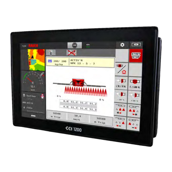
Page 8: Layout And Function
The most important information concerning the operation of the machine is displayed in the working screen. 2.1.1 Description of the working screen The exact representation of the working screen depends on the actual settings selected and on the machine type. 5903001 AERO ISOBUS... -
Page 9: Display Fields
The three display fields in the working screen can be individually adjusted and assigned the following values as desired: • Forward speed • Turns/kg • ha trip • kg trip • m trip • kg left • m left • ha left • Oil temperature AERO ISOBUS 5903001... - Page 10 Press the corresponding display field in the touch screen. The available options are displayed in a list. Select the new value to be assigned to the display field. Press the OK button. The working screen is displayed. The respective display field displays the new value. 5903001 AERO ISOBUS...
-
Page 11: Spreading Operation Status Display
Display of sections Fig. 4: Display of the section states Activated sections on entire working width Right section is reduced by several partial Reduce right section button sections Further display and setting options are explained in chapter 4 Operation. AERO ISOBUS 5903001... -
Page 12: Library Of Icons Used
2. Layout and function Library of icons used The AERO ISOBUS machine control unit displays icons for the individual menus and functions on the screen. 2.2.1 Navigation Symbol Meaning Go to the left; previous page Go to the right; next page... -
Page 13: Working Screen Icons
Distance Control (option) is active Reset the quantity adjustment to the pre-set application rate Switch between working screen and menu window Selection of the surplus/shortage quantity on the left, right or both spreading sides (%) Quantity adjustment + (plus) AERO ISOBUS 5903001... -
Page 14: Other Icons
Reduce left sections (minus) Increase right sections (plus) Reduce right sections (minus) 2.2.4 Other icons Symbol Meaning Fold in start sections and central sections of the boom Fold out start sections and central sections of the boom 5903001 AERO ISOBUS... - Page 15 Fold out end sections of the boom Lock boom Unlock boom Automatic axle suspension active Automatic axle suspension switched off Lift boom Lower boom Inclination of boom, lift left Inclination of boom, lift right Automatic retensioning of the boom during spreading operation AERO ISOBUS 5903001...
-
Page 16: Structural Menu Overview
2. Layout and function Structural menu overview 5903001 AERO ISOBUS... -
Page 17: Attachment And Installation
Due to the numerous configurations of tractor/machine/terminal, please contact your dealer for selecting the correct connection. Connections, sockets 3.2.1 Power supply The power supply of the machine control unit is implemented via the 9-pin socket at the rear of the tractor. AERO ISOBUS 5903001... -
Page 18: Operation
Observe the operator's manual of the terminal used. n Accessing the main menu Press the Working screen/main menu function key. See 2.2.2 Menus. The main menu is displayed. Accessing the sub-menu via the touch screen Press the button of the desired sub-menu. 5903001 AERO ISOBUS... -
Page 19: Main Menu
You will return to the previous menu. Press the Working screen/main menu key. You will return to the working screen. Press ESC. The previous settings are retained. You will return to the previous menu. Main menu Fig. 5: Main menu with sub-menus AERO ISOBUS 5903001... -
Page 20: Hydraulic Axle
If the suspension is not operated in automatic mode, there is a danger of damage to the machine. Make sure that the tractor unit's hydraulic system and the control unit are switched on. Access the menu Main menu > Hydr. axle suspension. 5903001 AERO ISOBUS... - Page 21 After pressing the function keys, the hydraulic cylinders are retracted or extended. This may cause injury. Before adjusting the suspension manually, ensure that nobody is present in the danger zone of the machine. Press the Retract cylinder function key. Press the Extend cylinder function key. AERO ISOBUS 5903001...
-
Page 22: Fertilizer Settings
Calibration factor for the revolutions of 4.5.2 Turns pro kg the metering rollers per kilogram. Is determined by means of a calibration. Start calibration Accessing the sub-menu for executing 4.5.3 Calibration the calibration Fertiliser chart Management of fertilizer charts 4.5.4 Fertilizer charts 5903001 AERO ISOBUS... -
Page 23: Application Rate
Enter the new value in the input field. Press OK. The new value is saved in the machine control unit. 4.5.2 Turns pro kg In this menu, you can enter the calibration factor of the desired revolutions per kilogram for the metering rollers. AERO ISOBUS 5903001... -
Page 24: Calibration
If the fertilizer quality has changed significantly (moisture, high dust content, granulate damage) • If a new fertilizer type is used The calibration must either be conducted with a running PTO at a standstill or while driving over a test section. 5903001 AERO ISOBUS... - Page 25 Enter the new designation in the input field Fertiliser name. Select the desired section for the calibration test. To do so, check the bock under the section number. Section 3 is selected by default. Press the OK button. Page 2 appears. AERO ISOBUS 5903001...
- Page 26 Press the OK button. Page 5 appears. Fig. 10: Calibration menu, page 5 Press the start/stop function key. The calibration procedure now runs automatically until metering switches off independently after 80 s. The display switches to page 6. 5903001 AERO ISOBUS...
-
Page 27: Fertilizer Charts
Selecting a fertilizer chart affects the machine, fertilizer settings and the machine control unit. The set application rate is overwritten by the stored value from the fertilizer chart. Creating a new fertilizer chart You can create up to 30 fertilizer charts in the electronic machine control unit. AERO ISOBUS 5903001... - Page 28 Enter a name for the fertilizer chart. We recommend naming the fertilizer chart after the fertilizer. Specific fertilizers can thus be assigned to fertilizer charts more easily. Edit the parameters of the fertilizer chart. See 4.5 Fertilizer settings. 5903001 AERO ISOBUS...
- Page 29 The active fertilizer chart cannot be deleted. Select the option Delete element. The fertilizer chart is deleted from the list. n Managing the selected fertilizer chart via the working screen You can also manage the fertilizer chart directly via the working screen. AERO ISOBUS 5903001...
- Page 30 The active fertilizer chart is displayed. Fig. 12: Managing the fertilizer chart via the touch screen Button Application rate Button Fertiliser chart Enter the new value in the input field. Press OK. The new value is saved in the machine control unit. 5903001 AERO ISOBUS...
-
Page 31: Machine Settings
Selection/limitation of the speed signal • Speed AUTO (automated selection of either transmission or radar/GPS • GPS J1939 • NMEA 2000 The manufacturer does not assume any liability in the event of a loss of the GPS signal. AERO ISOBUS 5903001... -
Page 32: Auto/Man Mode
For uniform spreading of the spreading material, a constant forward speed must be applied in manual operating mode. Spreading in different operating modes is described in 5 Spreading operation. Menu Meaning Description AUTO km/h Selecting automatic mode Page 57 5903001 AERO ISOBUS... -
Page 33: Quantity
The speed calibration is the basic requirement for a precise spreading result. Factors such as tire size, a different tractor, all-wheel drive, slippage between tires and ground, ground characteristics, and tire pressure influence the speed measurement and therefore the spreading result. AERO ISOBUS 5903001... - Page 34 Access the menu Machine settings > Tractor (km/h). n Recalibrating the speed signal You can either overwrite an existing profile or create a profile in an empty memory location. In the Tractor (km/h) menu, select the desired profile. Press the Enter key. 5903001 AERO ISOBUS...
- Page 35 Press Start at the starting position of the reference distance. The pulse display is now zero. The machine control unit is ready for counting pulses. Drive along the 100 m long reference distance. Stop the tractor at the end of the reference distance. AERO ISOBUS 5903001...
-
Page 36: Folding The Boom In/Out
Only fold the booms in or out when the attached spreader is at a standstill. Ensure that nobody is present in the hazard zone. Access the menu Main menu > Boom folding. Fig. 16: Menu Boom folding Always keep an eye on the boom while folding it. 5903001 AERO ISOBUS... - Page 37 As soon and the pendulum frame is unlocked, spreading can start even if the end sections are folded in. Press the Fold out end sections function key until the boom end sections are fully folded out on both sides. The end sections are folded out. AERO ISOBUS 5903001...
-
Page 38: Folding In The Boom
The boom rests on the supports on the side of the hopper. The transport locks are closed. Manual adjustment of the boom The DistanceControl function (special equipment) automatically adjusts the height and the inclination. Manual adjustments are also possible if the DistanceControl function is deactivated or not available. 5903001 AERO ISOBUS... -
Page 39: System/Test
Use the function keys [2] on the left or right side to increase the inclination of the boom for the slope. System/Test In this menu, the system and test settings for the machine control unit can be configured. Access the menu Main menu > System / Test. AERO ISOBUS 5903001... -
Page 40: Total Data Counter
In this menu, all of the spreader's counter readings are displayed. • spread quantity in kg • spread area in ha • spread time in h • distance traveled in km This menu is for information purposes only. 5903001 AERO ISOBUS... -
Page 41: Test/Diagnosis
Before carrying out the tests, ensure that nobody is present in the danger zone of the machine. Sub-menu Meaning Description Voltage Checking the operating voltage Metering RPM Page 46 Distance Control Level sensor Checking the level sensors Wheel speed Blower Hydr.axle suspension AERO ISOBUS 5903001... - Page 42 Bar graph: Fill level of oil reservoir temperature value Status display Status display Signal display Temperature value The Signal display shows the status of the electrical signal for the fill level sensor and the temperature sensor. n Example: LIN bus 5903001 AERO ISOBUS...
- Page 43 When the system is restarted, the status is checked and typically reset. Since the status is not always reset automatically in certain cases, it is now also possible to perform a manual RESET. • Press the Reset error button. n Example of empty indicator AERO ISOBUS 5903001...
- Page 44 Status information of the empty indicator Hopper is full (values in percent) sensor in the left hopper n Example Distance Control Access the menu Test/diagnosis > Distance Control. The display shows some information and possible errors of the Distance Control function. 5903001 AERO ISOBUS...
- Page 45 For all other sources of error, register with the customer service department and provide the error code. Current height of left/right boom end section If the value 65535 is displayed, there is no communication to the controller (ECU-Mode 120) AERO ISOBUS 5903001...
- Page 46 Current working height of the boom Mean value of the two ultrasonic sensors Before exiting the menu, reset all check marks as shown in figure Fig. 23 Test/diagnosis; Example: Distance Control. n Example Metering RPM 5903001 AERO ISOBUS...
- Page 47 The error/status bits are displayed for each metering unit in line Err [6]. If no error is present and no calibration is executed, the line is blank. Several errors can be displayed at the same time. The various states are described in the table below. AERO ISOBUS 5903001...
- Page 48 For any other source of error, contact the Customer Service department and provide the error code. Resetting the revolutions: Press the Reset button. The speed of the metering valves is now set to 0 rpm. 5903001 AERO ISOBUS...
-
Page 49: Service
The information list depends on the equipment of the machine. 4.11 Weighing/Trip counter This menu provides values regarding spreading work carried out and functions for the weighing operation. Access the menu Main menu > Weighing/Trip count.. The Weighing/Trip count. menu appears. Fig. 25: Menu Weighing/Trip count. AERO ISOBUS 5903001... -
Page 50: Trip Counter
If you wish to continuously observe the values during spreading, you may also assign the freely selectable display fields in the working screen kg trip, ha trip or m trip, see 2.1.2 Display fields. Fig. 26: Menu Trip counter Spread quantity, area and distance display Delete trip counter fields 5903001 AERO ISOBUS... -
Page 51: Rest (Kg, Ha, M)
The Application rate and Working width values cannot be changed in this menu. They are for information purposes only. Fig. 27: Menu Rest (kg, ha, m) Input window kg rest Application rate, Working width, possible spread area and distance display fields For machines without weigh cells AERO ISOBUS 5903001... -
Page 52: Using The Joystick
CCI A3 Joysticks operating levels You can switch between three operating levels with the shift key. The plane that is active in each case is indicated by the position of an illuminated bar at the lower edge of the display. 5903001 AERO ISOBUS... -
Page 53: Cci A3 Joystick Button Functions
The joystick offered is pre-programmed with specific functions at the factory. The meaning and function of the icons can be found in Chapter 2.2 Library of icons used. Please note that the functions of the buttons vary depending on machine type. AERO ISOBUS 5903001... - Page 54 4. Operation Fig. 30: Button functions Level 1 Fig. 31: Button functions Level 2 5903001 AERO ISOBUS...
-
Page 55: Wifi Module
Transmission of information from the fertilizer charts app to the ECU. This way, the fertilizer settings no longer need to be entered manually. • Transmission of the residual material weight display from the ECU on the smartphone. AERO ISOBUS 5903001... - Page 56 4. Operation Fig. 33: WiFi module You can find more information on assembly of the WiFi module and communication with the smartphone in the WiFi module assembly instructions. • The WiFi password is: quantron. 5903001 AERO ISOBUS...
-
Page 57: Spreading Operation
This operating mode is applied by default for machines without a weighing system. Requirements for spreading: • The AUTO km/h operating mode is active (see 4.6.1 AUTO/MAN mode). • The fertilizer settings are defined: ○ Application rate (kg/ha), ○ Turns/kg AERO ISOBUS 5903001... -
Page 58: Spreading With The Man Km/H Operating Mode
Carry out a calibration in oder to determine the revolutions/kg of the metering rollers or enter the value manually. Pressing Start/Stop The spreading starts. Always observe the set forward speed during spreading. 5903001 AERO ISOBUS... -
Page 59: Automatic Re-Tensioning Of The Boom
The boom is folded out. See Chapter 4.7.1 - Folding out the boom - Page 36 Press the AUTO re-tensioning function key in the main menu. Re-tensioning is active. All boom cylinders are re-tensioned every 120 seconds for 5 seconds. DistanceControl n Optional equipment Contact your dealer to activate the function. AERO ISOBUS 5903001... -
Page 60: Alarm Messages And Possible Causes
Not enough oil in the oil reservoir • Oil too cold 109 Forward speed or application rate too low Minimum application rate alarm that has been set has been reached. Minimum speed that has been set has been reached. 5903001 AERO ISOBUS... -
Page 61: Fault/Alarm
Observe the operating manual for the mineral fertilizer spreader. See also 6.1 Meaning of the alarm messages. ACK Press In the case of different ISOBUS terminals, acknowledging the alarm messages may differ. You can use various keys to acknowledge other messages with a yellow frame: • Enter • Start/Stop AERO ISOBUS 5903001... - Page 62 6. Alarm messages and possible causes For this purpose, follow the instructions on screen. 5903001 AERO ISOBUS...
-
Page 63: Special Equipment
7. Special equipment Special equipment Illustration Designation Level sensor CCI A3 joystick WiFi module DistanceControl AERO ISOBUS 5903001... -
Page 64: Guarantee And Warranty
• Claims for damage other than to the RAUCH devices will not be accepted. This also means that no liability will be accepted for damage resulting from spreading errors. Unauthorized modifications of the RAUCH devices may result in consequential damage, for which the manufacturer will not accept any liability.
Need help?
Do you have a question about the AERO ISOBUS and is the answer not in the manual?
Questions and answers