
Related Manuals for ADC FCS-717 4B


Summary of Contents for ADC FCS-717 4B
- Page 1 PG-F ECHNICAL RACTICE 19" C ENTRAL FFICE ERMINAL HELF Model List CLEI Code FCS-717 Section SCP-FCS717-042-03H...
- Page 2 Information furnished by ADC is believed to be accurate and reliable. In no event shall ADC be liable for any damages resulting from the loss of data, loss of use, or loss of profits and ADC further disclaims any and all liability for indirect, incidental, special, consequential or other similar damages.
- Page 3 SCP-FCS717-042-03H Using This Technical Practice SING ECHNICAL RACTICE Two types of messages, identified by icons, appear in the text: Notes contain information about special circumstances. Cautions indicate the possibility of equipment damage or the possibility of personal injury. FCS-717 List 4B January 6, 2003...
- Page 4 Using This Technical Practice SCP-FCS717-042-03H January 6, 2003 FCS-717 List 4B...
-
Page 5: Table Of Contents
SCP-FCS717-042-03H ABLE OF ONTENTS Product Overview_____________________________________________________________________ 1 Description and Features .....................1 Specifications........................2 Functional Description ........................2 Operational Capabilities ......................2 Backplane Connections .......................4 Installation and Test .........................10 Unpacking..........................10 Selecting HDSL Lines .......................10 Mounting ...........................11 Wiring ..........................11 Before You Begin....................11 Connect the Frame Ground .................12 Connect the CO Battery ..................13 Single Battery Feed..................13 Split Battery Feed ..................14... - Page 6 SCP-FCS717-042-03H January 6, 2003 FCS-717 List 4B...
- Page 7 SCP-FCS717-042-03H IST OF IGURES 1. FCS-717 List 4B COT Shelf (Card-side, Front View)..................1 2. FCS-717 List 4B COT Shelf Backplane ......................8 3. Mounting the FCS-717 List 4B COT Shelf....................11 4. Connecting the Frame Ground (Protection Ground) ..................12 5. Connecting a Single Battery Feed .........................13 6.
- Page 8 SCP-FCS717-042-03H January 6, 2003 FCS-717 List 4B...
- Page 9 SCP-FCS717-042-03H IST OF ABLES 1. Channel Unit Circuit Utilization ........................3 2. Channel Unit Circuit Utilization ........................3 3. FCS-717 List 4B Card Connectors........................4 4. Alarm Unit or PGTC Interface Unit Connector ....................5 5. Line Unit Connectors ............................6 6. Channel Unit Connectors Pinouts for Systems 1, 2, and 3................7 7.
- Page 10 SCP-FCS717-042-03H January 6, 2003 FCS-717 List 4B...
-
Page 11: Product Overview
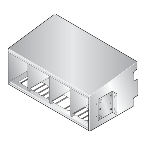
SCP-FCS717-042-03H RODUCT VERVIEW ® ® This section describes the ADC PG-Flex FCS-717 List 4B, 19-inch Central Office Terminal (COT) shelf description, features, and specifications. Description and Features The FCS-717 List 4B COT shelf (see Figure 1) supports: • one alarm unit or Pair Gain Test Controller (PGTC) Interface unit common to all systems •... -
Page 12: Specifications
Functional Description SCP-FCS717-042-03H • 25-pair Amphenol connector for PGTC test interface Specifications Electrical Characteristics Power -48 Vdc CO battery 133 Ω Composite Clock Termination Environmental Operating Temperature -40° F to +150° F (-40° C to +65° C) Operating Humidity 5% to 95% (non-condensing) Operating Elevation -200 feet to 13,000 feet (-60 m to 4000 m) Physical... -
Page 13: Channel Unit Circuit Utilization
SCP-FCS717-042-03H Functional Description Table 1. Channel Unit Circuit Utilization Channel Unit Service Configurations Channel Unit 8-Channel POTS 4-Channel ISDN 4-Channel DDS* T/R 1 Ckt 1 Ckt 1 Ckt 1 Tx T/R 2 Ckt 2 Ckt 2 Ckt 1 Rcv T/R 3 Ckt 3 Ckt 3 Ckt 2 Tx... -
Page 14: Backplane Connections
Channel Unit Connectors (Systems 1 thru 3) Table 6 page 7 Use the Information in Table 4 through Table 6 for diagnostic and troubleshooting procedures under the direction of an authorized ADC technical support representative. January 6, 2003 FCS-717 List 4B... -
Page 15: Alarm Unit Or Pgtc Interface Unit Connector
SCP-FCS717-042-03H Functional Description Table 4. Alarm Unit or PGTC Interface Unit Connector J1-C Pin J1-C Signal J1-B Pin J1-B Signal J1-A Pin J1-A Signal LGND (CDS) NMA_CD CRIT_MAJ_NO INHIBIT CRIT_MAJ_COM PGTC_TIP1 SLEEVE1 TESTIN-T_1 PGTC_RING1 SLEEVE2 TESTIN-R_1 PGTC_TIP2 SLEEVE3 TESTIN-T_2 PGTC_RING2 SLEEVE4 TESTIN-R_2 PGTC_TIP3... -
Page 16: Line Unit Connectors
Functional Description SCP-FCS717-042-03H Table 5. Line Unit Connectors System Line Unit Connector Signal* Signal* PROTGND PROTGND HDSL_TIP1_EX_n HDSL_TIP2_EX_n HDSL_RING1_EX_n HDSL_RING2_EX_n BATT_RTN BATT_RTN -48_n -48_n BATT_x-† BATT_x-† 8KHZ_CC N/C (BURN-IN) TSYNC_n TSIG_n TCLK_n TSER_n RSYNC_n RSIG_n RCLK_n RSER_n SDA_n CSYNC_n FUSEALARM SCL_n +5_n +5_n... - Page 17 SCP-FCS717-042-03H Functional Description Table 6. Channel Unit Connectors Pinouts for Systems 1, 2, and 3 System Channel Unit Connector System Channel Unit Connector System Channel Unit Connector 1 (4)* 2 (5)* 3 (6)* 1 (7)* 2 (8)* 3 (9)* Pin Signal Pin Signal Pin Signal Pin Signal...
-
Page 18: Fcs-717 List 4B Cot Shelf Backplane Connectors
Functional Description SCP-FCS717-042-03H Table 7 lists the FCS-717 List 4B COT shelf backplane connectors and where each is described in this practice. (Refer to Figure 2 for connector locations and refer to Figure 9 on page 19 for alarm terminations). Table 7. -
Page 19: Lan Connector
SCP-FCS717-042-03H Functional Description Table 8. Battery, CO Battery Return, and Frame Ground Connector Type Function Screw Battery (-48V_A) for systems 1 and 2 Screw Battery (-48V_B) for system 3 Screw CO battery return B (RTN _B) Screw CO battery return A (RTN_A) Screw Frame Ground (Protection Ground) Table 9. -
Page 20: Installation And Test
Upon receipt of the equipment: Unpack each container and visually inspect it for signs of damage. If the equipment has been damaged in transit, immediately report the extent of damage to the transportation company and to ADC. Order replacement equipment if necessary. -
Page 21: Mounting
SCP-FCS717-042-03H Installation and Test Mounting The FCS-717 List 4B COT shelf mounts in a standard 19- or 23-inch CO equipment bay. Use universal mounting brackets when installing the FCS-717 List 4B COT shelf onto a 19-inch frame or remove the two mounting brackets and reverse them to mount into a 23-inch frame. -
Page 22: Connect The Frame Ground
Installation and Test SCP-FCS717-042-03H Connect the Frame Ground CO battery return (RTN_A, RTN_B) is separate from frame ground in the PG-Flex equipment. CKT GND and CO battery return are connected inside the PG-Flex line unit but are not connected on the backplane. Follow the instructions below and refer to Figure 4 to connect the frame ground. -
Page 23: Connect The Co Battery
SCP-FCS717-042-03H Installation and Test Connect the CO Battery The FCS-717 List 4B COT shelf can be powered from a single battery feed or from a split battery feed. Use 12 AWG or larger wire (or multiple wires of a smaller gauge) to ensure good power connections to the PG-Flex system. -
Page 24: Split Battery Feed
Installation and Test SCP-FCS717-042-03H Split Battery Feed. For a split battery feed do the following (see Figure When using a split battery feed, -48V_A provides the battery feed for system 1 and 2, and -48V_B provides the battery feed for system 3. Remove and discard the jumper between TB1 and TB2. -
Page 25: Hdsl Pairs
SCP-FCS717-042-03H Installation and Test HDSL Pairs Connect the HDSL pairs as shown in Figure 7. Note that n is 1 for System 1, 2 for System 2, and 3 for System 3. Refer to Table 12 on page 16 for HDSL terminations and functions. Connect the HDSL Pair #1 onto wire-wrap pins HDSL_n_T1 (Tip) and HDSL_n_R1 (Ring) on the COT shelf for system n. -
Page 26: Hdsl, Test, And Miscellaneous Connectors
Installation and Test SCP-FCS717-042-03H Table 12. HDSL, Test, and Miscellaneous Connectors System* Connector Type Function System n HDSL_n_T1 .045 in. Tip and Ring terminations for HDSL Pair #1 of System n to Remote HDSL_n_R1 Wire-wrap Terminal n. The HDSL termination point for each system is: P5 for system 1, P6 for system 2, and P7 for system 3. -
Page 27: Bypass Pairs
SCP-FCS717-042-03H Installation and Test Table 12. HDSL, Test, and Miscellaneous Connectors * Where n is 1 for System 1, 2 for System 2, and 3 for System 3. † Connecting the inhibit pins of multiple PG-Flex systems that are sharing the same bypass pair prevents other systems from attempting to use the bypass pair when it is currently being used by another system. - Page 28 Installation and Test SCP-FCS717-042-03H Connect the INHIBIT line from one COT shelf in the system to the next COT shelf sharing the metallic bypass pair when the bypass pair is shared between multiple systems in multiple shelves. Repeat Step 2 Step 3 for each PG-Flex system in the cascade.
-
Page 29: Composite Clock
SCP-FCS717-042-03H Installation and Test Composite Clock When required for digital services, connect the composite clock as shown in Figure 9 (refer to Table 12 composite clock terminations and functions). You can cascade the composite clock to other PG-Flex shelves. When cascading the composite clock to other PG-Flex shelves, terminate only on the last shelf in the cascade. If the composite clock is connected, it must be terminated by connecting a jumper from CC1_TIP to CC1_TERM wire-wrap pins, and from CC2_TIP to CC2_TERM wire-wrap pins on the last shelf in the cascade. -
Page 30: Alarms
Installation and Test SCP-FCS717-042-03H Alarms If external audible and visual alarm indications are required, connect the audible and visual alarm leads from the CO alarm panel to the FCS-717 List 4B COT shelf alarm contacts (P22, see Figure 9 on page 19) according to local practice. -
Page 31: Systems 1 Through 3 Subscriber Amphenol Connectors
SCP-FCS717-042-03H Installation and Test Table 14. Systems 1 through 3 Subscriber Amphenol Connectors* Channel Unit Circuit Conn Pn† Tip Conn Pn† Ring BYPASS * Shaded terminations are used only with 8 Channel POTS and DDS Units. † Where n is 1 on System 1, 2 on System 2, and 3 on System 3. FCS-717 List 4B January 6, 2003... -
Page 32: Pgtc Connection
Installation and Test SCP-FCS717-042-03H PGTC Connection Connect the PGTC test interface cable to connector P26 (see Figure 10). Refer to Table 15 on page 23 for PGTC connector pinouts. PGTC connector (P26) SYSTEM 2 Figure 10. Connecting the PGTC Test Interface Cable January 6, 2003 FCS-717 List 4B... -
Page 33: Pgtc Connector Pinouts
SCP-FCS717-042-03H Installation and Test Table 15. PGTC Connector Pinouts Signal Signal PGTC_RING1 PGTC_TIP1 PGTC_RING2 PGTC_TIP2 PGTC_RING3 PGTC_TIP3 PGTC_RING4 PGTC_TIP4 SLEEVE2 SLEEVE1 SLEEVE4 SLEEVE3 PROCEED2 PROCEED1 PROCEED4 PROCEED3 LOCK2 LOCK1 LOCK4 LOCK3 TMAJ TSTALM SEZBY SEIZE FCS-717 List 4B January 6, 2003... -
Page 34: Auxiliary Power Pairs
Installation and Test SCP-FCS717-042-03H Auxiliary Power Pairs When a PG-Flex system is used with a doubler, wire the auxiliary power pairs to the COT shelf (Figure 11) as follows: Wire-wrap auxiliary power pair 1 to PWR_1_T1 (Tip) and PWR_1_R1 (Ring) for system 1. Wire-wrap auxiliary power pair 2 to PWR_2_T2 (Tip) and PWR_2_R2 (Ring) for system 2. -
Page 35: Cabling Verification
SCP-FCS717-042-03H Installation and Test Cabling Verification The following verifications should be done before any cards are inserted into the FCS-717 List 4B COT shelf. Verify that there is a minimum of -42 Vdc and a maximum of -56 Vdc between the TB1 (-48V_A) and TB4 (RTN_A) screw terminals on the COT shelf. -
Page 36: Product Support
ADC’s Return Material Authorization (RMA) Department. Call or write ADC’s RMA Department to ask for an RMA number and any additional instructions. Use the telephone number, fax number or email address listed below: •... - Page 37 If there is another reason for returning the equipment, please let us know so we can determine how best to help you. Pack the equipment in a shipping carton. Write ADC’s address and the RMA Number you received from the RMA Department clearly on the outside of the carton and return to: ADC DSL Systems, Inc.
-
Page 38: Fcc Classa Compliance
The FCC requires the user to be notified that any changes or modifications made to this device that are not expressly approved by ADC Technologies, Inc. voids the user's warranty. All wiring external to the product(s) should follow the provisions of the current edition of the National Electrical Code. -
Page 39: Acronyms
SCP-FCS717-042-03H Acronyms CRONYMS American Wire Gauge Central Office Terminal Channel Unit Dataphone Digital Service Digital Loop Carrier High bit-rate Digital Subscriber Line HDSL Integrated Services Digital Network ISDN Local Area Network Main Distribution Frame Network Management Access Pair Gain Test Controller PGTC Plain Old Telephone Service POTS... - Page 40 World Headquarters: ADC Telecommunications, Inc. 12501 Whitewater Drive Minnetonka, Minnesota USA 55343 For Technical Assistance: 800.366.3891 ´,Sj¶8B¨ 1251748...
Need help?
Do you have a question about the FCS-717 4B and is the answer not in the manual?
Questions and answers