Table of Contents
Advertisement
Quick Links
Advertisement
Table of Contents

Related Manuals for American Innovations APM4AM-SAT WS


Summary of Contents for American Innovations APM4AM-SAT WS
- Page 1 APM4AM-SAT WS Installation and Configuration Guide...
- Page 3 MERICAN NNOVATIONS APM4AM-SAT WS Installation and Configuration Guide ©American Innovations, Ltd. http://www.aiworldwide.com/ 12211 Technology Blvd • Austin, TX 78727 Phone: 512-249-3400 • Fax: 512-249-3444...
- Page 4 Reproduction in any manner whatsoever without the written permission of American Innovations is strictly forbidden. Trademarks used in this text: the American Innovations logo and icon are trademarks of American Innovations, Ltd. The Bullhorn logo and icon are registered trademarks of American Innovations, Ltd.
-
Page 5: Table Of Contents
Mounting Requirements .......3 APM4AM-SAT WS Receiver ......3 Universal Wireless Transmitter . - Page 6 Templates ........22 Event Log .
-
Page 7: Chapter 1. Installation
C h a p t e r 1 Installation Introduction This Installation and Configuration guide provides detailed information on how to install and configure a APM4AM-SAT WS (wireless sensor) unit. Chapter 1 describes the installation process. Configuration information is discussed in Chapter 2. Required Equipment... -
Page 8: Batteries
• Acrobat Reader version 5.0 or higher Batteries The APM4AM-SAT WS uses a rechargeable, sealed lead acid battery (12 volt, 3.4 Amp. Hr.). A battery charger is also included to keep the lead acid battery charged. A red LED indicates that the charger is in fast charge mode; a green LED indicates that the charger is in float charge mode. -
Page 9: Mounting Requirements
Mounting Requirements APM4AM-SAT WS enclosures can be mounted anywhere with a few precautions. The following list identifies certain conditions to consider when choosing a location to mount the unit. Mounting hardware suitable for the type of mounting surface is provided by the customer. For unit dimensions, refer to Figure 1-1. -
Page 10: Universal Wireless Transmitter
When an alarm condition is detected, an alarm is sent to designated locations, such as a cell phone. If an alarm is received, be sure to check all conditions of the APM4AM-SAT WS receiver, wireless transmitter, and sensors. If equipment appears to be working normally, check equipment batteries and ensure that the path between receiver and tranmitter is clear from obstructions. -
Page 11: Before Installing The Satellite Terminal
Once the wireless transmitter has been installed and powered on, ensure that the LCD display on the APM4AM-SAT WS receiver board is displaying READY Before Installing the Satellite Terminal The APM4AM-SAT WS uses SkyWave D+ Network Services to transmit data and alarm packets from the field to the website account. Test the satellite terminal to verify communications with the SkyWave satellite before you install the satellite terminal in the field. -
Page 12: Confirming The Satellite Look Angle
Look angle coordinates display under the cross hair cursor. The azimuth and elevation angle display under each satellite that provides coverage. A green colored satellite indicates good coverage, yellow indicates coverage but at a low elevation angle, and gray indicates no coverage. Record the look angle coordinates. -
Page 13: Installing The Apm4Am-Sat Ws
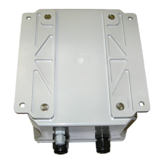
If the installation kit includes the optional mounting bracket kit, complete the following steps: Use a slotted screwdriver to loosen four (4) screws securing the mounting flanges on the back of the enclosure (Figure 1-3). Remove the mounting flanges. APM4AM-SAT WS Installation and Configuration Guide... - Page 14 Figure 1-3. APM4AM-SAT WS Enclosure (Back View) Install the mounting brackets (Figure 1-4) on the back of the enclosure using the provided hardware. Figure 1-4. Optional Mounting Bracket Mount the enclosure making sure the area around the enclosure provides enough working space to easily open the enclosure when performing routine maintenance or configuring the unit for service.
- Page 15 Create a strain relief for the interface cable using a tie wrap and one of the mounting holes on the mounting bracket. APM4AM-SAT WS Installation and Configuration Guide...
- Page 16 United States. Figure 1-7. Typical Satellite Terminal Installation Route the satellite terminal interface cable through the water-tight fitting on the bottom of the APM4AM-SAT WS enclosure. Connect the interface cable in the connector labeled on the Radio controller board.
- Page 17 You will need to either recharge or replace the battery to continue. After the main configuration window displays, click the Auto option box in the box. Update Communications Configuration procedures are described in Chapter 2. APM4AM-SAT WS Installation and Configuration Guide...
-
Page 18: Installing The Ac Battery Charger
Attach the battery charger cable to the AC battery charger terminals. Route the battery charger cable through the water-tight fitting on the bottom of the APM4AM-SAT WS unit. Connect the battery charge cable to the controller board in the slot labeled (see Figure 1-8 on page 11). -
Page 19: Troubleshooting
If you need assistance with the installation or configuration, contact American Innovations (AI) Technical Support: Table 1-1. How To Contact Technical Support 512-249-3400 Telephone: bhtechservices@aiworldwide.com Email: American Innovations, Ltd. Mail: ATTN. FDD Technical Services 12211 Technology Blvd. Austin, TX 78727 512-249-3444 Fax: APM4AM-SAT WS Installation and Configuration Guide... - Page 20 Chapter 1. Installation...
-
Page 21: Chapter 2. Configuration
You can start the Universal Configuration Tool (UCT) software by double-clicking the Bullhorn program icon on your computer desktop, or click Start > Programs > American Innovations > Configuration . When the software begins to initialize, a window displays with Toolkit the message “Connecting to unit”... -
Page 22: Main Configuration Window
Main Configuration Window The main configuration window (Figure 2-1) provides the controls to configure the unit for service. After configuring a unit, you can use the information on the main configuration window to monitor input channel readings, battery voltage level, test packet transmission status, and communications signal strength. - Page 23 RSSI reading. To view a “live” RSSI reading, select the check box to place a check mark Auto Update inside the check box. The UCT software updates the RSSI reading every 2 seconds when is selected. Auto Update APM4AM-SAT WS Installation and Configuration Guide...
-
Page 24: Unit Information
The APM4AM- RSSI/SkyWave Inmarsat D+ Satellite Network: SAT WS uses an RSSI that is on a scale from 0.00dB to 50.00dB. The RSSI reading indicates the strength of the signal received from the satellite. RSSI readings above 14dB indicate a strong signal and better communications with the satellite. -
Page 25: Battery Information
Channels (Figure 2-4) shows current configuration settings in the fields Channels labeled . The last input channel reading Alarms & Filters Input displays in the fields. Current Read Accumulator APM4AM-SAT WS Installation and Configuration Guide... - Page 26 Figure 2-4. Channels contains the following information: Channels Click the button to force the UCT Update / Auto Update: Update software to display a current reading for all input channels. Current readings display in the fields. Current Read Accumulator When is enabled, the UCT software displays a Auto Update...
- Page 27 Input columns show the same reading. Current Read Input • This column shows the last accumulator reading Accumulator: received by input channel 5 ( ). For all other input channels, column displays dashes. Accumulator APM4AM-SAT WS Installation and Configuration Guide...
-
Page 28: Templates
Templates The UCT software allows you to save certain configuration settings in a template on your computer for the unit you are currently configuring. You can then apply the template to another unit of the same type. After applying a template, use the UCT software to change or configure other settings as needed. -
Page 29: Configuring A Unit
Select the unit you want to configure and click Select The main configuration window displays. Press to verify the unit and UCT software are communicating. You can also click > to verify Tools Read Unit Settings communications. APM4AM-SAT WS Installation and Configuration Guide... -
Page 30: Loading A Template
Loading a Template Configuration templates can be created to easily configure multiple, similar units. If a template is available, you can load a template before configuring the unit. If no template is available, you can create one after configuring a unit. See Saving a Template on page 32 for details. The following procedure explains how to configure a unit using configuration settings that have previously been saved in a template. -
Page 31: Configuring Battery Information
Battery Type field. If you installed the battery today and your computer is configured with the correct date and time in Windows Control Panel, click the check box and then click Installed Today Save APM4AM-SAT WS Installation and Configuration Guide... -
Page 32: Configuring The Controller Clock
To set your computer with the correct date or time, click button on the Windows taskbar and then select Start Settings > Control Panel > Date/Time If you want to use a calendar to select the battery installation date, complete the following steps: Click the down arrow in the field (Figure 2-7). -
Page 33: Configuring A Transmission Schedule
Complete the following steps to configure the unit with a transmission schedule: Click in the box on the main Change Transmission Schedule configuration window to display the Transmission Schedule configuration window (Figure 2-9) APM4AM-SAT WS Installation and Configuration Guide... - Page 34 Figure 2-9. Transmission Schedule To set a transmission time: Select a time in the field. Transmit report at Click the up or down arrow buttons to move the time forward or backward. If you want to include an optional delay in the transmission schedule, click the check box.
-
Page 35: Configuring Input Channels In Active Digital Mode
Two separate data packets transmit to the website account when working with the unit. The unit transmits one packet for inputs 1 through 4 and a second packet for inputs 5 and 6. APM4AM-SAT WS Installation and Configuration Guide... - Page 36 Click the option button. Active Digital If you want to include a Debounce filter in alarm settings, review the following information and then type the number of polling cycles (for channels 1-4) or seconds (for channels 5 and 6) in the text box.
-
Page 37: Saving Configuration Settings In The Event Log
Sending test packet... • Starting test packet transmission... The UCT software displays a countdown sequence (in seconds) in the window until an acknowledgement is received or communications cannot be established with the Bullhorn website server. APM4AM-SAT WS Installation and Configuration Guide... -
Page 38: Saving A Template
If the status message Acknowledgement received from server appears, communication has been established with the Bullhorn website server. If the status message Test Packet Return Transmission Failed appears, communication has not been established with the server. Click again to send another test packet. If Transmit communication cannot be established after several attempts, call Technical Support for assistance. -
Page 39: Exiting The Uct Software
Click or press File > Exit Disconnect the configuration cable from the unit and your computer. Close the door on the APM4AM-SAT WS enclosure. Tighten the water-tight fittings on the bottom of the enclosure. APM4AM-SAT WS Installation and Configuration Guide... - Page 40 Chapter 2. Configuration...
-
Page 41: Appendix A. Technical Specifications
Output voltage (float/fast charge): 13.6-13.8/14.8-15 VDC • Output current: 50-1100 mA • Output current limit: Charger will shut down if output terminals are inadvertently shorted or excessive output current. Cycle input power to return charger to normal operation. APM4AM-SAT WS Installation and Configuration Guide... - Page 42 Satellite Terminal Environmental: • Operating temperature range: –40° to +70°C • Storage temperature range: –40° to +85°C • Humidity: 95% relative humidity at 30°C Electrical: • Input voltage: 9 VDC to 32 VDC • Transmit: 9W The satellite terminal contains no user serviceable parts or replaceable fuses.
-
Page 43: Appendix B. Regulatory Notices
A p p e n d i x B Regulatory Notices FCC Requirements The following FCC requirements are met by the product(s) described in this guide. This equipment has been tested and found to comply with the limits for a Class B digital device, pursuant to part 15 of the FCC Rules. -
Page 44: Export Control Classification Number
Export Control Classification Number The Export Control Classification Number (ECCN) assigned by the U.S. Bureau of Industry and Security (BIS) to the software and/or hardware products described in this manual is as follows: No Classification ECCN Classification: EAR99 or NLR ECCN Code: ... - Page 46 http://www.aiworldwide.com/ 12211 Technology Blvd. • Austin, TX 78727 Phone 512-249-3400 • Fax 512-249-3444 Part No. 122143-000, Rev. 1 • May 17, 2010...
Need help?
Do you have a question about the APM4AM-SAT WS and is the answer not in the manual?
Questions and answers