Table of Contents
Advertisement
Quick Links
Advertisement
Table of Contents

Related Manuals for RC4 Wireless LumenDim6


Summary of Contents for RC4 Wireless LumenDim6
- Page 1 LumenDim6 High Power Six-Channel Wireless Dimmer Quick Start Guide Rev. 1.1A...
- Page 2 2 3 7...
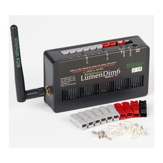
- Page 3 RC4 LumenDim6 1. DMX Data Indicator 2. Function and COP* Indicator 3. Function Button 4. Set ABC and Set DEF Buttons 5. DimA - DimF Dimmer Indicators 6. RF Connect Indicator for Transmitter Linking 7. RF Connect (Link) Button 8. Anderson PowerPole Connections for Power and Outputs 9.
-
Page 4: Registering Your Product
LumenDim6 Quick Start Guide This guide will get you started using your RC4 LumenDim6. Most LumenDim6 users will find all the information they need right here. Your LumenDim6 also has a wide variety of expanded features for advanced users. You can find out more about all of them in the RC4 Knowledge Base at http://rc4.info. - Page 5 PowerPole shells are available in a range of colors. Pins are available with 15A, 30A, and 45A ratings. If you are running your LumenDim6 at close to the maximum rated power handling, you MUST use 45A pins at the power input.
-
Page 6: Performing A Factory Reset
Performing a Factory Reset If someone else has used your LumenDim6, or you just want to get back to a known configuration, performing a factory reset is easy: Power on the device. The green COP indicator will be blinking. Press and hold Func, briefly tap (press and release) the SetABC button, then release Func. - Page 7 If the RF Connect LED remains on, or is blinking, repeat the process until it stays off. When the RF Connect LED is off, the LumenDim6 is ready to be linked to your transmitter. NOTE: Link status is not affected by performing a Factory Reset.
-
Page 8: Link Button
RF Connect LED. Tap it with a small screwdriver or the end of a bent paperclip. The blue RF Connect LEDs on both the LumenDimIO and the LumenDim6 will flash for several seconds and then remain steady, indicating that they are linked. -
Page 9: Setting The Dmx Address
Before changing any dimmer settings, play with the DMX levels for these addresses and see your wireless dimmer outputs work. The DimA, B, C, D, E, and F indicators on the side of the LumenDim6, below the grey negative terminals for each, are directly connected to the dimmer outputs: they show you exactly what the dimmers are doing. - Page 10 Subsequent Channel Assignment When you set DimABC, all 6 dimmers are automatically set sequentially. For example, if you have set DMX channel 60 for DimA, DimB is now assigned to channel 61, DimC is on 62, and so on, all the way up to DimF being set on channel 65.
- Page 11 Dimming occurs on the negative side. The positive connections are all connected together inside the LumenDim6. * DimC , D, E, and F on the LumenDim6 can control a variety of devices including solenoids, relays, servo motors, and much more. DimA and B are intended for LED dimming only.
- Page 12 All of the (+) terminals are connected together inside the LumenDim6. The two (+) terminals make it easy to connect two RGB light sources, each with their own common positive wire. Dimming happens on the negative (–) connections.
- Page 13 Choosing Other Dimmer Curves or Profiles The LumenDim6 default is the ISL dimmer curve, which is best for LEDs. This is also the curve that is selected with RC4 OneTouch™ when the DMX level is at 30%. There are dimmer curves for different kinds of lamps, motors, and more.
-
Page 14: Advanced Features
• Using a small adaptor cable, the LumenDim6 can be used as a wireless data receiver to deliver DMX to other devices. It can also be used as a wired DMX dimmer: the miniplug DMX port becomes an input when the device is not linked to a transmitter. - Page 15 Caring for Your LumenDim6 • The LumenDim6 should not be used with AC power or with any voltage higher than 35VDC. Doing so will severely damage the device and is extremely dangerous for the operator. • Do not exceed the maximum total power handling of the LumenDim6, which is 45A.
- Page 16 North Carolina, USA, Local +44 (0)20 3289 8765 London, UK 1-866-237-6641 Toll Free Fax, North America Email: support@theatrewireless.com Website: www.rc4wireless.com Knowledge Base: http://rc4.info We’re here to help you at any time. James David Smith President and Chief Product Designer RC4 Wireless...
Need help?
Do you have a question about the LumenDim6 and is the answer not in the manual?
Questions and answers