
Related Manuals for ZWAE ONIIIS


Summary of Contents for ZWAE ONIIIS
- Page 1 Zakład Wytwórczy Aparatów Elektrycznych Sp. z o.o. INSTALLATION AND SERVICE MANUAL ONIIIS Outdoor disconnector Manual No DTR.01.03.02.EN...
- Page 2 This personnel must know exactly all safety rules and rules for maintaining the device in accordance with these instructions. The problem-free and safe operation of this device requires proper transport, proper storage, construction and assembly as well as careful service and maintenance. zwae.com.pl...
-
Page 3: Table Of Contents
Zakład Wytwórczy Aparatów Elektrycznych Sp. z o.o. Table of contents 1. TRANSPORT AND STORAGE ......4 1.1. -
Page 4: Transport And Storage
Disconnector should be moved by grabbing the base frame. It is unacceptable to lift the disconnec- tor by grabbing the current paths. Figure 1 ONIIIS disconnector on the transport pallet screwed with screws. - Page 5 Zakład Wytwórczy Aparatów Elektrycznych Sp. z o.o. WARNING ! In case of disconnector equipped with earthing knives, the fastening screws (item 3) of the blockade ring (item 2) mounted on earthing knives's shaft, are loosen for de- livery time, what allows the earthing knives to be closed (with closed disconnector's current path).
-
Page 6: Transport And Storage
2. DESCRIPTION 2.1. Application The outdoor disconnectors of type ONIIIS are intended for usage in outdoor 24 kV and 36 kV switchgears. They are designed to close and open electrical circuits in a off-load condition. In the open position disconnectors cre-... -
Page 7: Construction And Principle Of Operation
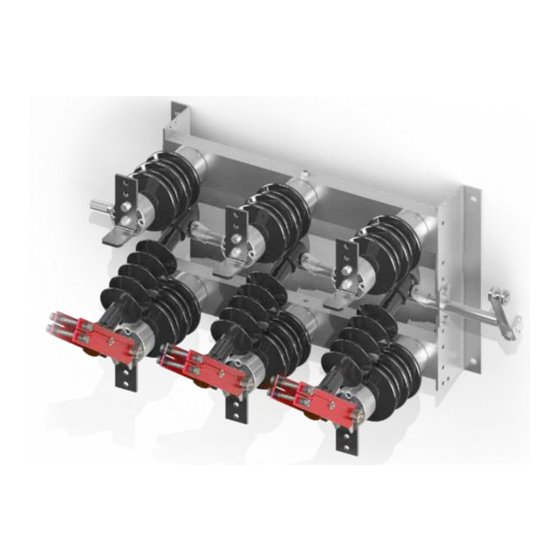
2.2. Construction and principle of operation The ONIIIS disconnectors are switches with a vertical movement of knifes of the current path. The base frame of the disconnector (item 1) is a welded steel frame in which sides the main shaft (item 2) is mounted. On the... -
Page 8: Ambient Conditions During Operation
ONIIIS-36/1600 ONIIIS-24/2000 Disconnector: ONIIIS-36/2500 Figure 5 Types of terminals of ONIIIS type disconnector 2.3. Ambient conditions during operation The ONIIIS disconnectors are adapted for outdoor operation, at ambient temperature from -40 to +40 ° C and relative humidity to 100%. -
Page 9: Nameplate
Zakład Wytwórczy Aparatów Elektrycznych Sp. z o.o. 2.4. Nameplate 3 8 4 10 Manufacturer Year of production Rated current I =800 A Rated duration of short-circuit t Serial number Rated operating voltage U [kV] Surge test voltage U [kV] Rated short-circuit current I [kA] Number of poles Creepage distance, 17 mm/kV... -
Page 10: Accessories, Additional Equipment
Zakład Wytwórczy Aparatów Elektrycznych Sp. z o.o. 3. ACCESSORIES, ADDITIONAL EQUIPMENT ONIIIS disconnector Manual sliding operating mechanism NNP with fix- Coupling tie rod Supporting bracket Figure 6 ONIIIS type disconnector with NNP operat- ing mechanism mounted on the ZN pillar... - Page 11 Zakład Wytwórczy Aparatów Elektrycznych Sp. z o.o. ONIIIS disconnector NR5S manual operating mechanism with fixing Coupling tie rod Supporting bracket Clamp Figure 7 ONIIIS disconnector with a wall-mounted NR-5S operating mechanism...
- Page 12 Zakład Wytwórczy Aparatów Elektrycznych Sp. z o.o. ONIIIS disconnector NSL-60 motor operating mechanism with fixing Coupling tie rod Supporting bracket Clamp Figure 8 ONIIIS disconnector with NSL-60 operating mechanism mounted on a spun pillar.
-
Page 13: Installation And Adjustment
4.1. Preparation of the supporting structure and assembly ot the disconnector ONIIIS disconnectors are intended for operation in horizontal and vertical positions, with movable contacts at the top. The design of the supporting structure should take into account keeping the appropriate insulation level to earth, and the construction itself should have adequate stiffness. -
Page 14: Connecting Feeding Wires And Grounding Wire
Zakład Wytwórczy Aparatów Elektrycznych Sp. z o.o. 4.2. Connecting feeding wires and grounding wire. Before screwing the rails, the terminals (item 3) of the disconnector should be cleaned of any contamination by a method that does not damage the silver coatings. It is recommended to use a soft, lint-free cloth for this purpose. -
Page 15: Operating Manual
- condition of insulators, special attention should be paid to contamination of their surfaces and possible mechani- cal damages (scratches, cracks, etc.); - main contacts condition paying attention to possible damage (traces of melting, silver coating defects) in places of their mutual contacts; zwae.com.pl... -
Page 16: Permitted Repairs Carried Out By The User
Zakład Wytwórczy Aparatów Elektrycznych Sp. z o.o. 5.2. Permitted repairs carried out by the user Disconnector repairs performed if necessary by the user should not go beyond the adjustment of contacts and mechanisms conditioning the proper operation of the apparatus. More complicated repairs requiring dismantling of the disconnector can only be carried out by the manufactur- er. -
Page 17: Utilization
70 µΩ Table 1 Resistances of ONIIIS type disconnectors 7. UTILIZATION The ONIIIS type disconnector is made of materials that are recyclable. The main materials from which the disconnectors are built are: - steel (painted, galvanized); - copper (painted, silver-plated);...
Need help?
Do you have a question about the ONIIIS and is the answer not in the manual?
Questions and answers