
Related Manuals for ZWAE ONIII


Summary of Contents for ZWAE ONIII
- Page 1 Zakład Wytwórczy Aparatów Elektrycznych Sp. z o.o. Disconnectors assembly manual ONIII Horizontal centre-break disconnector Manual No DTR.01.15.01.EN...
-
Page 2: Table Of Contents
Zakład Wytwórczy Aparatów Elektrycznych Sp. z o.o. Table of Contents 1. DELIVERY METHOD ......2. - Page 3 This personnel must know exactly all safety rules and rules for maintaining the device in accordance with these instructions. The problem-free and safe operation of this device requires proper transport, proper storage, construction and assembly as well as careful service and maintenance. zwae.com.pl...
-
Page 4: Delivery Method
In the event of any non-compliance or damage, notify the manufacturer immediately. 3. MOVING Crates with ONIII-123 disconnector parts can be safely moved with a forklift. It is allowed to lift the crates one at a time, by the pallet base, on either side of the crate. - Page 5 Zakład Wytwórczy Aparatów Elektrycznych Sp. z o.o. Fig. 3, 4. Permitted method of lifting transport crates It is advisable to leave disconnectors in the crates as long as possible and move them together to the final installation location. When stacking, pay special attention to the support points in the corners of the crates overlapping each other.
-
Page 6: Unloading
Zakład Wytwórczy Aparatów Elektrycznych Sp. z o.o. 4. UNLOADING The box with disconnector elements should be opened by removing the lid and then the side wall, where the operating mechanisms are packed. Fig. 6. The method of opening the transport crate Then, all available elements should be manually removed from the box: current paths, operating mechanisms, supporting structures, shafts and coupling rods, and the remaining side walls should be dismantled. -
Page 7: Assembly
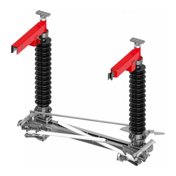
Zakład Wytwórczy Aparatów Elektrycznych Sp. z o.o. To unload the disconnector bases, use a forklift again. Remove the bases one at a time. Fig. 8. The way of lifting the disconnector base 5. ASSEMBLY To each of the bases, tighten the diagonal tie, freely suspended for the time of transport (marked in blue below).. Fig. - Page 8 Zakład Wytwórczy Aparatów Elektrycznych Sp. z o.o. Attach the insulators to the base. Use three M16x70 bolts and one M16x90 bolt for each of the insulators. Pay attention to the correct positioning of the bolts, especially the stop bolt. Fig. 10. Insulators installation Fig.
- Page 9 Zakład Wytwórczy Aparatów Elektrycznych Sp. z o.o. Fig. 13. Current paths assembly The diagonal tie (shown in Fig. 9) should be adjusted in such a way that when closing the disconnector, the gap between the female contact and the entering, male contact is within 3 - 5 mm. Fig.
- Page 10 Zakład Wytwórczy Aparatów Elektrycznych Sp. z o.o. Fig. 15. Correct closing depth of the current path Current path adjust- ment screws A stop bolt limiting the rotation angle of the current paths Fig. 16. Disconnector adjustment points In the next step, the tie rod connecting the disconnector's operating crank with the lever on the side of the right earthing switch should be adjusted.
- Page 11 Zakład Wytwórczy Aparatów Elektrycznych Sp. z o.o. In the next step, the tie rod connecting the disconnector's operating crank with the lever on the side of the right earthing switch should be adjusted. The tie is marked in blue in Fig. 17. Fig.
- Page 12 Zakład Wytwórczy Aparatów Elektrycznych Sp. z o.o. Fig. 19. Correct setting of the stop bolt Similarly, set the second of the stop bolts with the disconnector fully open. For a disconnector with two earthing switches, you should additionally pay attention that the driving crank of the left earthing switch does not collide with the knife of the right earthing switch throughout the entire range of motion, as shown in Fig.
- Page 13 Please carry out other assembly and adjustment steps in accordance with Manual No DTR 01.02.08, Chapter 3. Zakład Wytwórczy Address of correspondence: Kębłowo Nowowiejskie, ul. Łąkowa 2 Aparatów Elektrycznych Sp. z o.o. 84-351 Nowa Wieś Lęborska Gdańska 60, 84-300 Lębork POLAND POLAND zwae@zwae.com.pl tel.: +48 59 863 36 15 www.zwae.com.pl...
Need help?
Do you have a question about the ONIII and is the answer not in the manual?
Questions and answers