ZWAE ONIII Manual
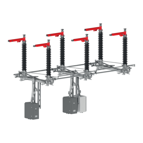
Outdoor disconnector 40ka
Hide thumbs
Also See for ONIII:
- Installation and service manual (20 pages) ,
- Assembly manual (13 pages)

Related Manuals for ZWAE ONIII


Summary of Contents for ZWAE ONIII
- Page 1 Zakład Wytwórczy Aparatów Elektrycznych Sp. z o.o. Installation and service manual ONIII Outdoor disconnector 40kA Manual No DTR.01.11.01.EN...
- Page 2 This personnel must know exactly all safety rules and rules for maintaining the device in accordance with these instructions. The problem-free and safe operation of this device requires proper transport, proper storage, construction and assembly as well as careful service and maintenance. zwae.com.pl...
-
Page 3: Table Of Contents
Zakład Wytwórczy Aparatów Elektrycznych Sp. z o.o. Table of Contents 1. TRANSPORT ........1.1 Unpacking and inspection . -
Page 4: Transport
Zakład Wytwórczy Aparatów Elektrycznych Sp. z o.o. 1. TRANSPORT 1.1 Unpacking and inspection Immediately after receiving the disconnector it should checked the delivery compliance with the shipping spec- ification. Then should be checked whether the disconnector has not been mechanically damaged during trans- port and the data on the nameplate match the order. - Page 5 Zakład Wytwórczy Aparatów Elektrycznych Sp. z o.o. During transport poles must be secured against tipping over and the central contact should be open. The dis- connector can be transported by means of transport with open cargo area. On flat, hard surfaces it is allowed to move the disconnector’s poles with a pallet truck in the manner shown below, with particular care to prevent the pole from tipping over.
-
Page 6: Description
2.1. Construction and principle of operation Outdoor disconnector type ONIII- ... is an insulating, two-column switch, with horizontal contacts movement. It is designed to work in networks with voltage corresponding to the rated voltage, at frequencies up to 60 Hz inclusive. -
Page 7: Nameplate
Zakład Wytwórczy Aparatów Elektrycznych Sp. z o.o. 2.3. Nameplate 2.4. Basic technical parameters Parameter Value Rated operating voltage 72,5 [kV] 123 [kV] Rated current 1600 [A] 1600 [A] Peak current 100 [kA] 100 [kA] Short-circuit current, 1-sec. 40 [kA] 40 [kA] Short-circuit current, 3-sec. -
Page 8: Installation And Adjustment
Zakład Wytwórczy Aparatów Elektrycznych Sp. z o.o. 3. INSTALLATION AND ADJUSTMENT The delivered disconnector is completely regulated and ready to work. Assembly is reduced to: a) installation poles on a supporting structure, b) attaching supporting construction for the operating mechanisms, c) installation of operating mechanisms, d) poles coupling and regulation, e) earthing switches coupling,... -
Page 9: Disassembly Of The Transport Lock
Zakład Wytwórczy Aparatów Elektrycznych Sp. z o.o. 3.3. Disassembly of the transport lock Remove the transport blockade from the poles attached to the supporting structure. To remove the blockage, unscrew the M10 screw in the disconnector base frame and the M12 screw in the drive lever has to be unscrewed. -
Page 10: Operating Mechanism Assembly
Zakład Wytwórczy Aparatów Elektrycznych Sp. z o.o. 3.4. Operating mechanism assembly The operating mechanism should be mounted on the supporting structure, under driving crank located in dis- connector base. After the operating mechanism is assembled, the coupling shaft must be attached to connect the operating mechanism to the crank. - Page 11 Zakład Wytwórczy Aparatów Elektrycznych Sp. z o.o. Coupling tie rod Tightening torque of M16 screws - 100 Nm. Poles coupling regulation consists of such a setting of the length of the tie rod and coupling lever location ad- justment so that the current paths at each pole reach the limit positions according to the following requirements.
- Page 12 Zakład Wytwórczy Aparatów Elektrycznych Sp. z o.o. Regulation process should be performed in following way: a) Initially coupling tie rods should be installed in such a way that one pole would not be connected (tie rod ending hang on a line below coupling lever); b) Coupling tie rod should be extended or shortened in such a way that current path in driving pole would be achieve require limit positions.
-
Page 13: Earthing Switches Coupling
Earthing switches have to be coupled using coupling shafts, which length is presented in the table below. Application Type Coupling shaft Coupling shaft – left earthing – right earthing switch switch ONIII-72 A = 735 A = 795 ONIII-123 A = 1335 A = 1395 Right earthing switch shaft Left earthing switch shaft... -
Page 14: Earthing Switches Operating Regulation
Zakład Wytwórczy Aparatów Elektrycznych Sp. z o.o. 3.7. Earthing switches operating regulation Earthing regulation consists of coupling shaft adjustment, in order to earthing blades on each pole should achieve end positions in accordance with requirements presented in the drawing below and earthing circuit closing occur simultaneously. -
Page 15: Grounding Of The Base Frames
Zakład Wytwórczy Aparatów Elektrycznych Sp. z o.o. 3.8. Grounding of the base frames After regulation of the disconnector and earthing knives the base frame should be grounded. Earthing connec- tion points are marked on the disconnector base. In the case of earthing the disconnector with built-in earthing switch, the earthing line should be connected as close as possible to the cable connecting the earthing switch knife with the base. -
Page 16: Inspections And Maintenance
Zakład Wytwórczy Aparatów Elektrycznych Sp. z o.o. c) The disconnector cannot be closed until its earthing switch has been opened. d) Disconnector earthing switch can be manueovered from open to close position only: • If the disconnector is in open position, •... -
Page 17: Spare Parts And Recommended Service Materials
40 years). If the disconnector is damaged due to improper assembly or operation, it is possible for the manu- facturer to repair it for a fee. Disconnector type ONIII does not possess parts, which should be replaced during normal operation in service life. -
Page 18: Utilization
Zakład Wytwórczy Aparatów Elektrycznych Sp. z o.o. 6. UTILIZATION The ONIII disconnectors are made of materials that are recyclable. The main materials from which the disconnectors are built are: • steel (hot-dip galvanized); • aluminum; • copper. The disconnectors do not contain any dangerous substances. In accordance with applicable regulations, it is possible to return a worn out, complete disconnector to the manufacturer.
Need help?
Do you have a question about the ONIII and is the answer not in the manual?
Questions and answers