Table of Contents
Advertisement
Quick Links
MAN436
Setup and User's Manual
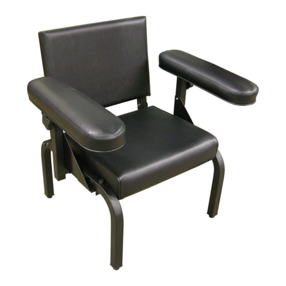
Models 76870
76870V
Adjustable Arm Subject's Chair
Setup and User's Manual
3700 Sagamore Pkwy N
Lafayette, IN 47904
Tel: (765) 423-1505
Fax: (765) 423-4111
info@lafayetteinstrument.com
www.lafayetteinstrument.com
Phone: (765) 423-1505 . info@lafayetteinstrument.com
Copyright © 2013-2018 Lafayette Instrument Company, Inc. All Rights Reserved: Rel. 2.22.18
Advertisement
Table of Contents

Subscribe to Our Youtube Channel
Related Manuals for Lafayette Instrument 76870

Summary of Contents for Lafayette Instrument 76870
- Page 1 Adjustable Arm Subject’s Chair Setup and User’s Manual 3700 Sagamore Pkwy N Lafayette, IN 47904 Tel: (765) 423-1505 Fax: (765) 423-4111 info@lafayetteinstrument.com www.lafayetteinstrument.com Phone: (765) 423-1505 . info@lafayetteinstrument.com Copyright © 2013-2018 Lafayette Instrument Company, Inc. All Rights Reserved: Rel. 2.22.18...
- Page 2 Adjustable Arm Subject’s Chair Parts Included (not actual size) 3700 Sagamore Parkway North . Lafayette, IN 47904...
- Page 3 Setup and User’s Manual Part A: qty 4 Part B: qty 6 Part C: qty 6 Part D: qty 4 Part E: qty 12 Part F: qty 4 Part G: qty 2 Part H: qty 2 Part I: qty 6 Part J: qty 2 Part M: qty 4 Part P: qty 4...
- Page 4 Adjustable Arm Subject’s Chair Setup Instructions Step 1 Required • Part E: qty 4 • 3/16" Hex Key 1. Attach the angles to the seat as shown. Do not tighten completely. Step 2 Required • Part B: qty 6 • Part C: qty 6 • Part I: qty 6 • 9/16"...
- Page 5 Setup and User’s Manual Step 3 Required • Part M: qty 4 • Part N: qty 2 • Part P: qty 2 5. Attach the square nuts to the handles as shown. The large handle goes on the L shaped piece.
- Page 6 Adjustable Arm Subject’s Chair Step 5 Required • Part A: qty 2 • Part D: qty 2 • Part J: qty 2 • 9/16” Wrench • 3/16” Hex Key 7. Attach the back piece as shown. Put the clevis pin through the plate and back tube and secure in place with the cotter pin.
- Page 7 Setup and User’s Manual Step 7 Required • Part E: qty 8 • 3/16” Hex Key 10. Attach the arm cushions to the plates. 11. Slide the arms into the arm support tubes as shown. Turn the knob clockwise to tighten into place at desired height.
- Page 8 Email: eusales@lafayetteinstrument.com 10 days of the original delivery. Please call the Lafayette Instrument Customer Phone, Fax, Email or Mail-in Orders Service Department for repair or replacement of the damaged merchandise.
Need help?
Do you have a question about the 76870 and is the answer not in the manual?
Questions and answers