
Subscribe to Our Youtube Channel
Related Manuals for ChM 3.4099


Summary of Contents for ChM 3.4099
- Page 1 ST/80-402 4.0ChLP distal ulnar plates 3.4099 • SURGICAL TECHNIQUE • IMPLANTS • INSTRUMENT SET www.chm.eu...
- Page 2 Before using the product, carefully read the Instructions for Use supplied with the product. It contains, among others, indications, contraindications, side effects, recommendations and warnings related to the use of the product. The above description is not a detailed instruction of conduct. The surgeon decides about choosing the operating procedure. www.chm.eu Document No ST/80-402 Date of issue 21.07.2017...
-
Page 3: Table Of Contents
TABLE OF CONTENTS 1. INTRODUCTION 2. IMPLANT DESCRIPTION 3. SURGICAL TECHNIQUE 3.1. PATIENT’S POSITIONING 3.2. SURGICAL APPROACH 3.3. FRACTURE REDUCTION 3.4. IMPLANT SELECTION 3.5. PLATE INSERTION 3.6. TEMPORARY PLATE STABILIZATION 3.7. INSERTION OF LOCKING SCREW IN THE EPIPHYSIAL PART OF THE PLATE 3.8. -
Page 5: Introduction
This surgical technique applies to 4.0ChLP locked plating system used for distal ulna bone osteosynthesis. The plates are a part of the ChLP locked plating system developed by ChM. The presented range of implants is made of materials in accordance with ISO 5832 standards. Compliance with the requirements of quality management systems and the requirements of Directive 93/42/EEC concerning medical devices guarantee high quality of the offered implants. -
Page 6: Implant Description
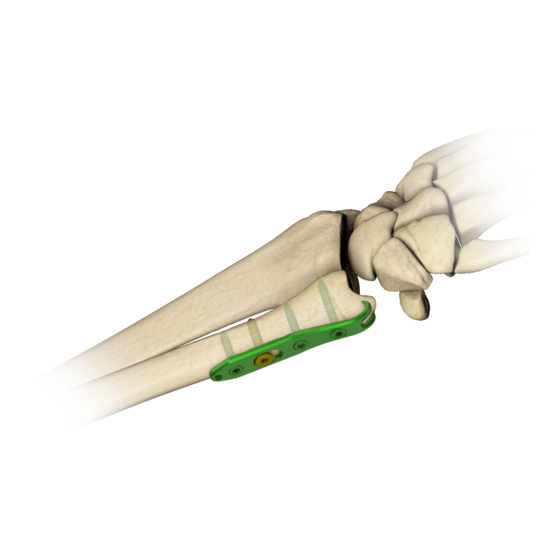
2. IMPLANT DESCRIPTION Distal ulnar plates are a part of 4.0ChLP system. This system includes also compatible locking screws. To facilitate their identification, both titanium plate and screws are green anodized. Hook at the end of plate: Locking holes: • stabilization of the distal ulna •... - Page 7 4.0ChLP distal ulnar plate 7/22...
-
Page 8: Surgical Technique
3. SURGICAL TECHNIQUE 3.1. PATIENT’S POSITIONING It is recommended to position the patient supine, with the hand in the pronation resting on the operating table. 3.2. SURGICAL APPROACH A posteromedial approach is recommended. Make a longitudinal skin incision between 4-6 cm in length. Make sure the dorsal sensory branch of the ulnar nerve is not damaged. -
Page 9: Temporary Plate Stabilization
3.6. TEMPORARY PLATE STABILIZATION The position of the implant may be stabilized by inserting Kirschner wire into appropriate hole or using setting-compressing screw (acc. to procedure 4a). NOTE: Confirm the correct position of the implant by taking X-Ray image. 3.7. INSERTION OF LOCKING SCREW IN THE EPIPHYSIAL PART OF THE PLATE Insert a locking screw of a proper length in the locking hole of the epiphysial part of the plate. -
Page 10: Insertion Of Locking Screws In The Shaft Part Of The Plate
3.9. INSERTION OF LOCKING SCREWS IN THE SHAFT PART OF THE PLATE Insert 4.0ChLP screw 2.4 [3.5164] of a proper length in the locking hole of the shaft part of the plate. 3.10. WOUND CLOSURE Before closing the wound, take an X-Ray image in at least two projections to confirm implant position and fracture reduction. -
Page 11: Surgical Procedures
4. SURGICAL PROCEDURES 4a. PROCEDURE OF TEMPORARY IMPLANT STABILIZATION Stabilization using Kirschner wire • Stabilize temporary the implant inserting Kirschner wire 1.0/180 [40.4814.000] into dedicated hole in the plate. 40.4814.000 Stabilization in locking holes using Kirschner wires • Insert threaded guide M3.5/1.8-4.0 [40.4896.018] into locking hole of the plate. -
Page 12: 4B. Procedure Of Cortical Self-Tapping Screw 2.7 [3.1220] Insertion
4b. PROCEDURE OF CORTICAL SELF-TAPPING SCREW 2.7 [3.1220] INSERTION Compression guide positioning NEUTRAL POSITION: Position the compression guide 1.8 [40.4897.018] in a desired position: 40.4897.018 COMPRESSION POSITION: NEUTRAL POSITION: Push the guide to the plate. It will position itself so that neutral insertion of the screw is allowed. -
Page 13: 4C. Procedure Of 4.0Chlp Screw 2.4 [3.5164] Insertion
4c. PROCEDURE OF 4.0ChLP SCREW 2.4 [3.5164] INSERTION Threaded guide insertion Insert threaded guide M3.5/1.8-4.0 [40.4896.018] into the threaded hole of the plate. 40.4896.018 Hole drilling Drill using drill 1.8/180 [40.2063.181] until a desired depth is reached. 40.2063.181 Measurement of hole depth OPTION I: Determine the length of the screw to be used using locking screw length measure [40.4818.100]. -
Page 14: 4D. Procedure Of 4.0Chlp Screw Va 2.4 [4.5235] Insertion
4d. PROCEDURE OF 4.0ChLP SCREW VA 2.4 [4.5235] INSERTION Guide VA positioning • Insert the guide VA 1.8 [40.5928.018] into the locking hole co-axially. • Set the desired inclination of the guide in relation to the locking hole axis. The guide enables the inclination of 15° in each direction with respect to the axis of the locking hole.. -
Page 15: Postoperative Procedure
5. POSTOPERATIVE PROCEDURE Introduce appropriate postoperative treatment that is determined by the physician. In order to avoid patient’s movement limitations, introduce exercises as soon after surgery as possible. However, make sure that the limb is not fully loaded before fragments osteosynthesis is complete. 6. -
Page 16: Catalogue
7. CATALOGUE PAGES 7a. INSTRUMENT SET 40.5711.200 Instrument set for 4.0ChLP Name Catalogue No. 40.4896.018 Threaded guide M3.5/1.8 -4,0 40.4897.018 Compression guide 1.8 Guide VA 1.8 40.5928.018 40.4814.000 Kirschner wire 1.0/180 40.2063.181 Drill 1.8/180 Length measure of locking screw 40.4818.100 Depth measure 40.4640.000 40.5682.000... -
Page 17: 7B. Implants
7b. IMPLANTS 4.0ChLP distal ulnar plate Ster Ster 3.5164.006-040 Ø24 3.4099.603 Cobalt 4.5235.006-040 3.4099.604 Ø24 3.4099.605 3.5164.006-040 * holes number in shaft part of the plate Ø24 3.1220.006-040 Ø27 3.5164.006-040 Ø24 17/22... -
Page 18: 7C. Screws
7c. SCREWS 4.0ChLP screw 2.4 4.0ChLP screw VA 2.4 Ster Ster Ster Ster Ø4.0 4.5235.006 3.5164.006 4.5235.008 3.5164.008 4.5235.010 3.5164.010 4.5235.012 3.5164.012 4.5235.014 3.5164.014 4.5235.016 3.5164.016 4.5235.018 3.5164.018 4.5235.020 3.5164.020 4.5235.022 3.5164.022 4.5235.024 3.5164.024 4.5235.026 3.5164.026 4.5235.028 3.5164.028 4.5235.030 3.5164.030 4.5235.032 3.5164.032 4.5235.034... -
Page 19: Instructions For Use
13. The implant may break or become damaged as a result of strenuous activity or trauma, ing techniques, and who has acquired practical skills of using ChM instrument set. The selec- and may need to be replaced in the future. - Page 20 5. Insertion, removal and adjustment of implants must only be done with instruments specially designated for those implants and manufactured by ChM sp. z o.o. 6. Use of ChM’s implants and instruments in combination with implants and instruments from other manufacturers may cause damage or failure of those implants or instruments and may lead to improper course of surgery and healing process.
- Page 21 1 liter of water. Immerse the product in the solution, exposure time – 15min (follow the information 1. For the production of instruments, ChM sp. z o.o. uses mainly: steel, aluminum alloys and plastics, approved for contained in the instructions prepared by the manufacturer of the agent, in respect of temperature, concentra- use in surgical instruments and in accordance with applicable procedures.
- Page 22 ChM sp. z o.o. Lewickie 3b 16-061 Juchnowiec Kościelny Poland tel. +48 85 86 86 100 fax +48 85 86 86 101 chm@chm.eu www.chm.eu 0197...
Need help?
Do you have a question about the 3.4099 and is the answer not in the manual?
Questions and answers