
Summary of Contents for Hitachi Kokusai Electric RU-1200JY
- Page 1 HD COLOR CAMERA SYSTEM REMOTE CONTROL UNIT RU-1200JY/VR OPERATING INSTRUCTIONS Please read these operating instructions carefully for proper operation, and keep them for future reference.
- Page 2 Note: The model and serial numbers of your product are important for you to keep for your convenience and protection. These numbers appear on the nameplate located on bottom of the product. Please record these numbers in the spaces provided below, and retain this manual for future reference.
-
Page 3: Table Of Contents
Contents Outline and features ............................Facility names and functions ..........................Function menu ..............................Operation procedure ............................10 Service information ............................32 Specifications ..............................33... - Page 4 SAFETY INSTRUCTIONS Carefully read all safety messages in this manual and safety Instructions on your equipment. Follow recommended precautions and safe operating practices. SAFETY ALERT SYMBOL This is the “Safety Alert Symbol.” This symbol is used to call your attention to items or operations that could be dangerous to you or other persons using this equipment.
- Page 5 IMPORTANT SAFETY INSTRUCTIONS 1. Read Instructions All the safety and operating instructions should be read before the product is operated. 2. Retain Instructions The safety and operating instructions should be retained for future reference. 3. Heed Warnings All warnings on the product and the operating instructions should be adhered to. 4.
- Page 6 14. Lightning For added protection for this product during a lightning storm, or when it is left unattended and unused for long periods of time, unplug it from the wall outlet. This will prevent damage to the product due to lightning and power-line surges.
- Page 7 WICHTIGE SICHERHEITSANWEISUNGEN 1. Alle Anweisungen lesen. Vor Betrieb des Erzeugnisses sollten alle Sicherheits-und Bedienungsanleitungen gelesen werden. 2. Die Anweisungen aufbewahren. Die Sicherheits-und Bedienungsanleitungen sollten fünftigen Bezug aufbewahrt werden. 3. Warnungen beachten. Die Warnungen auf dem Erzeugnis und in den Bedienungsanleitungen solten beachtet werden. 4.
- Page 8 14. Blitzschlag Für zusätzlichen Schutz des Erzeugnisses während eines Gewitters oder bei Nichtverwendung für lange Zeit den Stecker aus der Steckdose ziehen. Dies verhütet Beschädigung durch Blitzschlag und Netzspannungsstöße. 15. Überlastung Wandsteckdosen, Verlängerungskabel und eingebaute Bequemlickkeitssteckdosen nicht überlasten, da dies Feuer oder elektrischen Schlag verursachen kann. 16.
- Page 9 MISES EN GARDE IMPORTANTES 1. Lire les instructions Lire toutes les instructions de sécurité et de fonctionnement avant de faire fonctionner l’appareil. 2. Conserver ces instructions Conserver les instructions de sécurité et de fonctionnement á des fins de référence ultérieure. 3.
- Page 10 14. Foudre Pour renforcer la protection de l’appareil pendant un orage, ou si l’on s’en éloigne ou qu’on reste longtemps sans l’utiliser, le débrancher de la source d’alimentation. Ceci permettra d’éviter tout dommage de l’appareil dú á la foudre et aux surtensions de ligne. 15.
- Page 11 Operation of this product in a residential area is likely to cause harmful interference in which case the user will be required to correct the interference at his own expense. WARNING Changes or modifications not expressly approved by Hitachi Kokusai Electric responsible for compliance could void the user’s authority to operate the equipment. For Canada This product does not exceed the class A/class B limits for radio noise emissions from digital apparatus as set out in the radio interference regulations.
-
Page 12: Outline And Features
The RCU and CCU can be up to 10 meters apart. With the one touch color temperature control function, the RU-1200JY/VR is ideal not only Studio but also OB van use. RU-1200JY: Lens iris control, pedestal control and preview switch are assembled with an axis joystick control knob. -
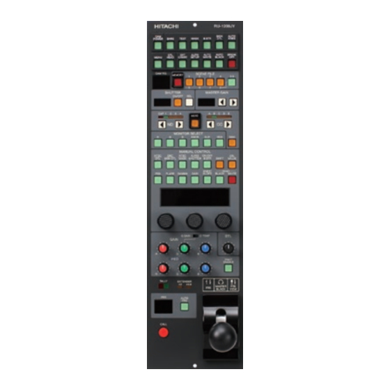
Page 13: Facility Names And Functions
Facility names and functions (Front) FRONT VIEW (JY type) Camera power on/off Each type on/off control Menu switch: Menu is displayed on the pix monitor with Color bar ON. Auto setup selection switch: External chart, Auto white & black and Break OFF for stop the auto set up process Scene file select and memory Shutter control: In Sequence and Variable... - Page 14 Facility names and functions (Front) FRONT VIEW (VR type) Camera power on/off Each type on/off control Menu switch: Menu is displayed on the pix monitor with Color bar ON. Auto setup selection switch: External chart, Auto white & black and Break OFF for stop the auto set up process Scene file select and memory Shutter control: In Sequence and Variable...
- Page 15 Facility names and functions (Rear) REAR VIEW Remote-Input connector Input and output remote control data between the camera control unit . EXT IRIS connector Connect to the external iris control module (optional) PRE VIEW Connector (JY type only) Connect to preview switcher to switch the preview monitor input.
-
Page 16: Function Menu
Function menu The camera head is connected with the CCU and the RU/SU as an operational camera system, The CCU output display TOP MENU on the PIX out monitor as follows. This is for Video operator at the CCU. PIX MENU: open this menu by pushing the MENU SW in the RCU. - Page 17 Function menu 1. COLOR menu structure which are displayed in the Pix monitor or are displayed in the viewfinder with at control head mode. MAIN MENU SUB-MENU...
- Page 18 Function menu 2. DETAIL menu structure which are displayed in the Pix monitor or are displayed in the viewfinder with at control head mode. MAIN MENU SUB-MENU...
- Page 19 Function menu 3. MAINTENANCE menu structure which are displayed in the Pix monitor or are displayed in the viewfinder with at control head mode. SUB-MENU MAIN MENU...
- Page 20 Function menu 4. FILE menu is displayed in the Pix monitor or are displayed in the viewfinder with at control head mode. 5. SETUP CARD...
-
Page 21: Operation Procedure
Operation procedure Item Function Switch Operating procedure Camera head switch on Power supply on The camera head power on by this switch pressing. The camera head power off by this switch pressing more than 2 seconds continuously. On/off control Color bar on/off selection Test signal on/off selection HD masking on/off selection Black stretch on/off selection. - Page 22 Item Function Switch Operating procedure AUTO SETUP Switch settings can be combined with the following auto setup modes. (1) Grayscale auto setup (2) Auto skin tone 2 times) (3) Auto Shading 3 times) 1.Conduct grayscale auto setup following procedure. (1) Set the switch to on to show the grayscale chart positioning markers...
- Page 23 Item Function Switch Operating procedure AUTO SETUP 2. Auto skin tone (1) Press the times to show the center marker on the viewfinder and PIX monitor screen. (2) Align the marker with the image for color phase detection. (3) Press the to detect the color phase at the marker position and revise the skin DTL phase data.
- Page 24 Item Function Switch Operating procedure AUTO WHITE Pickup a white scene and press the for automatic white balance adjustment. At error, the LED flashes for several seconds and the buzzer sounds. AUTO BLACK Press the to cut off the light and automatically adjust the black balance.
- Page 25 Item Function Switch Operating procedure Scene file Scene file adjustment values can be stored memory in memory by the following procedure. (1) Press the switch. (2) The LED begins blinking. (3) Press the scene file ( – ) for storing data in the memory. (4) The selected scene file LED flashes and LED lights for about 3 seconds.
- Page 26 Item Function Switch Operating procedure ND/CC selects ND filters or CC(ECC) filters. Each filters status are shown by the upper section ND/CC LEDs of these switches. LEDs and filters relationship are as shown below. CC(ECC) CAP:CAP A:3200K 1:CLEAR B:4300K 2:CROSS C:5600K 3:1/16ND D:6300K...
- Page 27 Item Function Switch Operating procedure Manual adjustment Select adjustment items with the manual control section switches. The display section shows the adjustment item and value. Use the rotary encoder to adjust the items for optimum values. Adjustment When the switch is on, the value display adjustment value is displayed from -100 to +100.
- Page 28 Item Function Switch Operating procedure Manual adjustment Press again the switch for the following display. (4)DETAIL KNEE WHT: Additional white component glare reduction. BLK: Additional black component glare reduction. Press the switch for the following display. (5)BALANCE P/N: Detail positive (white) side adjustment (4/8~8/4) (6)WHITE DTL Press again the switch for the following display.
- Page 29 Item Function Switch Operating procedure Manual adjustment (3)NTSC(PAL) Press again the switch for the following display. CRISP (4)NTSC(PAL) Press again the switch for the following display. DTL KNEE (5)NTSC(PAL) Press again the switch for the following display. BALANCE Skin detail adjustment (1)SKIN DTL Display...
- Page 30 Item Function Switch Operating procedure Manual adjustment (4)PHASE/WIDTH Press again the switch for the following display. (Ch2) PH-C: Skin color phase select (coarse adjustment) (R-MG,MG-B,B-CY,CY-G,G-YE,YE-R) PHAS: Skin color phase select (fine adjustment) WIDH: Skin color phase range select (5)CHROMA Press again the switch for the following display. LEVEL-DEP THRH: Skin detail reduction by color phase adjustment...
- Page 31 Item Function Switch Operating procedure Manual Adjustment (1)ENC TIMING Display SC-C: Subcarrier phase adjustment (coarse) SC-P: Subcarrier phase adjustment (fine) H-P: H phase adjustment (2)Y/C LEVEL Again press the switch for the following display. Y: Encoder Y level adjust C: Encoder C level adjust (3)ENC TIMING 2 Again press the switch for the following display.
- Page 32 Item Function Switch Operating procedure Manual adjustment Masking adjustment (1)Skintone Display SAT: Skintone saturation adjustment HUE: Skintone hue adjustment (2) R (Red) Again press the switch for the following display. SAT: R (red) saturation adjustment (following the same for each color). HUE: R (red) hue adjustment (following the same for each color).
- Page 33 Function Switch Operating procedure Manual adjustment (9) B-C Again press the switch for the following display. (Blue-Cyan) (10) B (Blue) Again press the switch for the following display. (11) M-B Again press the switch for the following display. (Magenta-Blue) (12) M (Magenta) Again press the switch for the following display.
- Page 34 Item Function Switch Operating procedure Manual adjustment Shutter adjustment Display VAR: Variable adjust 1/59~1/1983 (1080i/60) 1/50~1/2008 (1080i/50) Set the upper shutter switches to variable mode when Variable adjustment. Auto iris adjust (1)IRIS GATE Display Gate: Auto iris gate selection (1 – 6, see figure) The above gate signal is displayed also on CCU pix monitor.
- Page 35 Item Function Switch Operating procedure Manual adjustment (2)IRIS TRIM Press again the switch for the following display. SPED: Adjusts the auto iris response speed. If response speed becomes fast then adjustment value will be big and adjustment value become small then response speed will be slow. P/AV: Adjusts the ratio between peak and average.
- Page 36 Item Function Switch Operating procedure Manual adjustment Black stretch Display adjustment LEVL: Black stretch level adjustment On/off control (1) DTL Display DTL KNEE SKIN GATE DTL: Detail on/off DTLKNE: Detail knee on/off GATE: Skintone gate on/off Press again the switch for the following display. (2) KNEE W.CLIP GAMMA...
- Page 37 Item Function Switch Operating procedure Manual adjustment Press again the switch for the following display. (5)SKINDTL- CH,IND CH:Select skintone detail channel (1,2,1+2) IND:Select skintone gate channel l (1,2) (6) ASPECT Press again the switch for the following display. COMB FILTER MONO ASPCT: Selects aspect ratio (16:9 or 4:3) COMB: NTSC(PAL) output comb filter on/off...
- Page 38 Item Function Switch Operating procedure Manual adjustment BLACK adjustment (1) BLACK Display Pedestal (RGB) adjustment (2) BLACK SETUP LEVEL Black setup level adjustment (0~12.3%) Flare adjustment (1)FLARE Display Flare (RGB) adjustment (2) FLARE SETUP LEVEL Flare setup level adjustment (0~24.7%)
- Page 39 Item Function Switch Operating procedure Manual adjustment Gamma adjustment (1) GAMMA Display Gamma (R, G, B) adjustment (2) PAINT Press again the switch for the following display. - GAMMA Paint gamma (R,TOTL, B) adjustment (3) GAMMA TABLE Special gamma (rising component) adjustment (3.0~8.0(0.5step)) (4) GAMMA SETUP LEVEL...
- Page 40 Item Function Switch Operating procedure Manual adjustment Knee/slope adjustment (1) KNEE Display Knee point (R, total. B) adjustment (2) SLOPE Press again the switch for the following display. Slope (R, total, B) adjustment (3)WHITE CLIP Press again the switch for the following display. White clip (total) adjustment (4)KNEE SAT Knee saturation level adjustment...
- Page 41 Item Function Switch Operating procedure Gain and black Gain and black adjustment with adjust switch on Adjustable by control Setting to off returns black control to center detent position. G.gain/C.temp Set to C.Temp to operate the G.Gain control as adjust follows.
- Page 42 Item Function Switch Operating procedure Lens extender Lights when lens extender X2 is on. Indication Lights when lens extender X0.8 is on. TALLY CALL R tally LED lights when switch is pressed. Tally call from camera head and CCU: The R tally LED lights and the buzzer sounds.
-
Page 43: Service Information
Service information... -
Page 44: Specifications
Specifications Rating (1) Dimensions: 102 (W) x 370 (D) x 55 (H) mm (2) MASS: 1.5 kg (3) Power input: DC+12V (4) Ambient temperature: 0 to +40 C Dimensions RU-1200JY... - Page 45 Specifications Rating (1) Dimensions: 102 (W) x 340 (D) x 55 (H) mm (2) MASS: 1.5 kg (3) Power input: DC+12V (4) Ambient temperature: 0 to +40 C Dimensions RU-1200VR...
Need help?
Do you have a question about the RU-1200JY and is the answer not in the manual?
Questions and answers