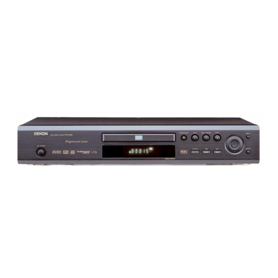
Denon DVD-900 Service Manual
Hide thumbs
Also See for DVD-900:
- Operating instructions manual (100 pages) ,
- Service manual (42 pages) ,
- Specifications (2 pages)
Advertisement
Quick Links
For Asia & Australia model
SERVICE MANUAL
DVD-900
MODEL
DVD VIDEO PLAYER
This service manual is composed of only pages whose contents are different
from those for the model DVD-900. For servicing, refer to the previously
issued service manual of DVD-900 (X0156-2) at the same time.
Some illustrations using in this service manual are slightly different from the actual set.
16-11, YUSHIMA 3-CHOME, BUNKYOU-KU, TOKYO 113-0034 JAPAN
Telephone: 03 (3837) 5321
X0156-2 NC 0209
Advertisement

Summary of Contents for Denon DVD-900
- Page 1 DVD VIDEO PLAYER This service manual is composed of only pages whose contents are different from those for the model DVD-900. For servicing, refer to the previously issued service manual of DVD-900 (X0156-2) at the same time. Some illustrations using in this service manual are slightly different from the actual set.
-
Page 2: Table Of Contents
TABLE OF CONTENTS TROUBLESHOOTING..............3 BLOCK DIAGRAMS. -
Page 3: Troubleshooting
TROUBLESHOOTING FLOW CHART NO.1 The power cannot be turned on.(1) See FLOW CHART No.3 <The fuse blows out.> Is the fuse normal? Is normal state restored when once unplugged Check if there is any leak or shor-circuit on the power cord is plugged again after several seconds? primary circuit component? (Q1001, Q1003,T1001, D1001, D1002, D1004, D1005, D1011, C1003, C1005) - Page 4 FLOW CHART NO.4 When the output voltage fluctuates. Does the photo coupler circuit on the secondary Check the circuit and replace the parts. side operate normally? (IC1001, IC1006, D1048, D1015) Does the photo coupler circuit on the primary side Check the circuit and replace the parts. operate normally? (IC1001, D1020, D1024) FLOW CHART NO.5...
- Page 5 FLOW CHART NO.8 No operation is possible from the remote control unit. Operation is possible from the DVD, but no operation is possible from the remote control unit. Is no operation possible if replacing the remote Original remote control unit is poor. control unit? Is 5V voltage supplied to Pin(3) terminal of infrared Check EV 5V line.
- Page 6 FLOW CHART NO.13 PON 1.8V is not outputted. Check D1013, C1014 and the periphery circuit. Is 2.5V voltage supplied at pin(1) of IC1002? Check PWRCON line. Is the "H" pulse inputted into pin(4) of IC1002? Replace IC1002. FLOW CHART NO.14 The disc tray cannot be opened and closed.
- Page 7 FLOW CHART NO.17 [No Disc] is indicated. (When the focus servo is not functioning.) Replace the DVD Main CBA Unit. No improvement can be found. The malfunction of the original DVD Main CBA Unit. Replace the DVD Mecha. FLOW CHART NO.18 [No Disc] is indicated.
- Page 8 FLOW CHART NO.20 Picture does not appear normally. Set the disc on the disc tray and playback. Replace the DVD Main CBA Unit or DVD Mecha . Are the video signals outputted to each pin of CN1601 on the the AV CBA? CN1601 10PIN CVBS CN1601...
- Page 9 FLOW CHART NO.21 Audio is not outputted. Set the disc on the disc tray and playback. Replace the DVD Main CBA Unit or DVD Mecha. Are the analog audio signals outputted to each pin of CN1601 on the AV CBA? CN1601 16PIN AUDIO-L CN1601 18PIN AUDIO-R Are the analog audio signals inputted to each pin...
-
Page 10: Block Diagrams
Video Block Diagram DATA(VIDEO) SIGNAL DATA(AUDIO) SIGNAL VIDEO SIGNAL DATA(VIDEO/AUDIO) SIGNAL IC601 (DVD HOST PROCESSOR) CACHE SUBSYSTEM FROM DVD PARA0 INTERNAL CENTRAL FRONT-END PCM-BCK SIGNAL PROCESS PARA0-PARA7 PERIPHERALS COMMAND & LINK PCM-DATA0 BLOCK DIAGRAM PARA7 PORTS PORT INTERFACE PCM-SCLK TO AUDIO AUDIO BLOCK PCM-LRCLK... -
Page 11: Schematic Diagrams / Cba's And Test Points
AV 1/3 Schematic Diagram CAUTION ! CAUTION Switching power supply circuit is used in this unit. FOR CONTINUED PROTECTION AGAINST FIRE HAZARD, If Main Fuse (F1001) is blown, check to see that all components in the REPLACE ONLY WITH THE SAME TYPE FUSE. power supply circuit are not defective before you connect the AC plug to NOTE : the AC power supply. - Page 12 AV 2/3 Schematic Diagram ‑ 12 ‑...
-
Page 13: Wiring Diagrams
WIRING DIAGRAM VIDEO-Y VIDEO-U VIDEO-V VIDEO AUDIO AUDIO DIGITAL OPTICAL S-VIDEO AC CORD OUT(L) OUT(R) AUDIO OUT AUDIO OUT CN2002 CN2201 KEY-5 KEY-6 KEY-7 AV CBA KEY-8 FUNCTION CBA KEY-4 KEY-3 CN1001 CN1601 KEY-1 KEY-2 OC-KEY CN501 CN701 DVD MAIN CBA UNIT JP1003 WJ1003 JP1004... -
Page 14: Exploded Views
EXPLODED VIEWS Cabinet 2L011 2L011 See Electrical Parts List for parts with this mark. Some Ref. Numbers are not in sequence. 2L011 2L011 2L021 2L021 2L021 2L031 DVD-900G0EA, DVD-900BKEA W1601 JK1401 JK1403 JK1201 DVD Main W1001 2L031 CBA Unit IC1204 AC1001 F1001 2L051... - Page 15 Packing X10A Unit - 15 -...
-
Page 16: Parts List
PARTS LIST Note: The symbols in the column "Mark" indicate the following distinations. A: DVD-900GOEA(For Australia gold model) B: DVD-900BKEA(For Australia black model) C: DVD-900GOE1(For Asis model) Ref. No. Mark Description Parts No. (DE)Part No. QTY. FRONT ASSEMBLY 0VM203739A 9H26000244 FRONT ASSEMBLY 0VM203740A 9H26000245...


Need help?
Do you have a question about the DVD-900 and is the answer not in the manual?
Questions and answers