Table of Contents
Advertisement
Quick Links
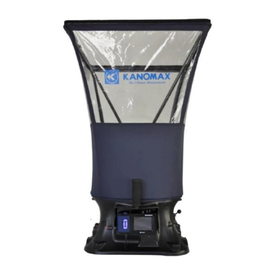
TABmaster Model 6715
Instruction Manual
Be sure to read this manual thoroughly before using the instrument ,
fully understand and pay attention to each cautions mentioned.
Please well-keeping this manual for long time service reference.
01003
14.10
www.lazodecontrol.com
+51 960 810 089
ventas@lazodecontrol.com
Advertisement
Table of Contents

Subscribe to Our Youtube Channel
Related Manuals for Kanomax TABmaster 6715


Summary of Contents for Kanomax TABmaster 6715
- Page 1 TABmaster Model 6715 Instruction Manual Be sure to read this manual thoroughly before using the instrument , fully understand and pay attention to each cautions mentioned. Please well-keeping this manual for long time service reference. 01003 14.10 www.lazodecontrol.com +51 960 810 089 ventas@lazodecontrol.com...
-
Page 2: Table Of Contents
CONTENTS Product Configuration........................3 Caution............................5 1. Introduction ..........................7 1.1. Features..........................7 1.2. Specifications ........................7 2. Outlook & Structure ........................8 2.1. Base structure ........................8 2.2. Micromanometer ....................... 9 3. Settubg up ........................... 9 3.1. Capture Hood ........................9 3.2. - Page 3 6.2.1. Tools ........................19 6.2.2. ID application ......................20 6.2.3. Test Mode .......................20 6.2.5. Data record ......................21 6.2.6. Standard/Actual test ....................21 6.2.7. Compensation factor ....................22 7 Error and Troubleshooting......................23 8 Warranty and Service ........................24 8.1. Product Warranty ......................24 8.2. After service........................24 www.lazodecontrol.com +51 960 810 089 ventas@lazodecontrol.com...
-
Page 4: Product Configuration
Product Configuration. 6715 Standard: Item. Micromanometer Model 6700 Instrument Base Fabric Hood: 2ft×2ft Carrying case Portable handle Frames Poles Communication cable Calibration certificate CD-Rom Manual and software inside Quick-Guide 6715 Optional Parts: Item. Specifications Spare hood 2x2ft Spare hood 2x4ft Spare hood 1x4ft Spare hood 3x2ft Spare hood 3x3ft... - Page 5 6700 Standard: Item. Micromanometer Model 6700 Carrying case Pressure tubing Communication cable Calibration certificate CD-Rom Manual and software inside Quick-Guide 6700 Optional Parts: Item. Specifications Velocity Grid Pitot tube (2.3 x 200mm) Pitot tube (4 x 300mm) Pitot tube (8 x 500mm) Pressure tubing 2*250cm Shoulder Strap...
-
Page 6: Caution
If abnormal smells, noises or s moke occur, or if liquid enters the ins trument, pull out the AC adapter and remove the batteries immedia tel y. Then send i t to the maintena nce Dept. of KANOMAX for after servi ce. Using properly or, there is possible of an electri c shock or a fi re or instrument malfunction. - Page 7 CAUTION Alwa ys unplug when the instrument not in use. Failure to do so ma y cause an electri c shock, an fire or ci rcui t da mage. Using properly Remove the ba tteries when s tori ng the instrument for a l ong period. Do not lea ve the exhaused batteries in the ba ttery compa rement and exchange the ba ttereis on time.
-
Page 8: Introduction
1. Introduction TABmaster Model 6715 is a kind of intelligent test instrument with multi functional of airflow test, velocity test and micro-Differential pressure test. It s widely used in air flow and velocity testing of air - conditioning, HAVC system and other places, especially for the high precision micro differential pressure test. 1.1. -
Page 9: Outlook & Structure
2. Outlook & Structure Frame Poles Pi vot Wi ndow Fabri c Hood Ins trument Mi cromanometer Base 2.1. Base structure 1 Outlook Potable handle Mi cromanometer Ba ck pressure ON/OFF Adjus t handle Base buttom Test handle 2 Internal view 3 Grid Ba ck pressure plate Testing... -
Page 10: Micromanometer
2.2. Micromanometer Ba ttery Compa rtment Cover Displa y LCD Keypad Cover lock Front view Ba ck Mini USB Port Power on/off Ai r port Ai r port Top view Bottom view 3. Settubg up 3.1. Capture Hood 1 Fabric Hood & basement Note Make sure the elastic band of the fabric hood is placed exactly as shown (Figure(3)) to ensure a good fit. -
Page 11: Velocity Grid
Note: ing. To remove the poles, simply reverse the steps. 3 Potable handle Note: Release the poles and portable handle when packing in the carring case to avoid case damaged. 4 Micromanometer & basement (+) (-) Note: 1 Correct install the micromanometer to the base with the same S/N No. 2 Do not cross- insert the Air pines just refer to the figure as above. -
Page 12: Pitot Tube
Grid Ha ndle Note: Mounting angle between the Grid and handle can be adjusted as request. 3.3. Pitot tube Air flow and velocity testing can be achieved when micromanometer work together with Pitot tube. Sta ti c pressure port Testing point 3.4. -
Page 13: Operating Instruction
4. Operating Instruction 4.1. Power supply 1 Power by AC adapter. AC adapter will be as the priority power supply when the AC adapter and batteries are all available using. The specification of the AC adapter is: I/P:AC 110-240V 50/60HZ O/P:DC 5V/2A 1 AC adapter for the master 2 AC adapter for Capture Hood 2 Power by battery... -
Page 14: Keypad Operation
Single START SAVE MENU 1. Start On Press button POWER for 2 seconds for start On, displaying KANOMAX then enter into the testing interface. 2. Power Off Press POWER for 2 seconds, shut down and power off. 4.3. Keypad operation Keypad panel includes control buttons, back-pressure switch and LCD adjusting keys. -
Page 15: Function Test
Ba ck pressure Ba ck pressure 3 LCD adjusting Note 1 Please switching the handle slow gently during LCD adjusting. 2 Stop turning when reach to the bound, for avoiding over turning and handle falling down. 5. Function test Besides the airflow test, if along with other optional products, test air velocity and micro -differential pressure is available. -
Page 16: Single Mode
working tools. E. Keypad current status indicating and the grey state is not available. F. Testing mode display the current testing mode G. Cycle recorded Cycle quantity H. ID current ID quantity Power supply AC adapter or batteries Blue tooth status when blue tooth working, the icon display or no icon display with closed. -
Page 17: Menu Setting
In order to reduce the measure error of the pressure loss,which causing from the hood to the system and 1500 get the more real air flow, we suggest testing under the Back Pressure Mode when air flow more than 2014 / 03 / 20 2014 / 03 / 20 13 : 10 2014 / 03 / 20... -
Page 18: General Setting
6.1. General setting 1 Basic setting MENU General Setting 1 Date Date 2014 / 03 / 20 Time 13 : 10 General Setting 2 Time Auto Shut DOWN DOWN Backlight High 3 Auto Shut Communicate 4 Backlight Test Setting 5 Communicate EXIT BACK 6.1.1. -
Page 19: Backlighting
General Setting General Setting 2014 / 03 / 20 Date 2014 / 03 / 20 Data (1)Press for options cha nge. Time Time 13 : 10 13 : 10 DOWN Auto Shut DOWN Auto Shut (2)Press for save settings . 10 min Backlight High... -
Page 20: Test Setting
General Setting Date 2014 / 03 / 20 Time 13 : 10 DOWN Auto Shut Backlight High Communicate BACK Communicate Computer Computer Printer Comfirm the Connection DOWN DOWN Bluetooth Waiting... BACK BACK Print Communicate Print By IDs Computer Print By Cycles Printer DOWN DOWN... -
Page 21: Id Application
The TABmaster model 6715 is an instrument for airflow, air temperature, and relative humidity measurements. The optional accessories (Velocity Grid, Pitot tube, and Micromanometer) expand the parameters that the instrument can measure. Refer to the Chapter 3 and 5 for details. Test Setting Select Tool Select Tool... -
Page 22: Data Record
6.2.4. Units Unit Test Setting Select Tool Airflow (1)Press for options cha nge. Test ID Atoms DOWN DOWN Test Mode RunAvg Temperature (2)Press for save settings . Unit Data Record (3)Press for quit. Std/Act K factor 1.000 BACK BACK Unit Unit Airflow Airflow... -
Page 23: Compensation Factor
Note Standard Test (Std): in the condition of atmosphere 101.3kPa and temperature 21.1 . Actual Test(Act): in actual condition with the compensation for the atmosphere and temperature. No Std/Act selection when in Micromanometer testing. When doing actual testing under Velocity Matrix and pitot tube, manually input the current temperature is needed for the compensation. -
Page 24: Error And Troubleshooting
7 Error and Troubleshooting Symptom Possible causes Corrective action incorrect specification of the AC Check and refer to Chapter4.1 Adapter in Manuel Check and refer to Chapter4.1 No display when power On Battery installation error in Manuel Low or dead battery power Replace the batteries Connection cable loss with the Display... -
Page 25: Warranty And Service
This limited warranty covers all defects encountered in normal use of the PRODUCT, and does not apply in the following cases: (1) Use of parts or supplies other than the PRODUCT sold by KANOMAX GROUP COMPANIES, which cause damage to the PRODUCT or cause abnormally frequent service calls or service problems. - Page 26 Repair after warranty expiration: Upon request, we will repair the instrument at performance is found to be recoverable by providing the repair. Replacement parts are available for a minimum period of five (5) years after termination of production. This storage period of replacement parts is considered as the period during which we can provide repair service.
Need help?
Do you have a question about the TABmaster 6715 and is the answer not in the manual?
Questions and answers