Graco Matrix B Series Instruction Manual
Hide thumbs
Also See for Matrix B Series:
- Instructions-parts list manual (45 pages) ,
- Manual (10 pages) ,
- Instructions manual (10 pages)
Table of Contents
Advertisement
Quick Links
Instruction Manual
Transceiver
249020, Series B, Transceiver with Full Line Matrix
249884, Series B, Transceiver with Full Line Matrix
249021, Series B, Transceiver with Tank Level Monitor Software, North America
249885, Series B, Transceiver with Tank Level Monitor Software, Australia
117256, Series C, Transceiver without Software, North America
120108, Series C, Transceiver without Software, Australia
Important Safety Instructions
Read all warnings and instructions in this
manual. Save these instructions.
For use with Matrix Total Fluid
Management System Components
The Matrix Transceiver contains an RF device with the following approvals:
FCC ID: JHIGNET
IC: 4840AGNET
Industry Canada Statement
The term "IC" before the certification/reg-
istration number only signifies that the In-
dustry Canada technical specifications
were met.
Graco Inc. P.O. Box 1441 Minneapolis, MN 55440-1441
Copyright 2003, Graco Inc. is registered to I.S. EN ISO 9001
http://gracomanual.com
™
Software, North America
™
Software, Australia
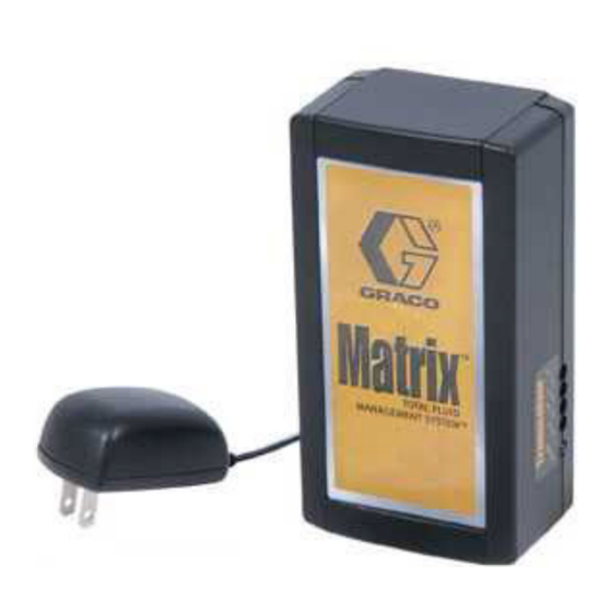
Part No. 117256 Shown
✓
Australian Vendor Code: N3845
309498H
EN
117256 shown
Advertisement
Table of Contents

Related Manuals for Graco Matrix B Series


Summary of Contents for Graco Matrix B Series
- Page 1 Industry Canada Statement The term “IC” before the certification/reg- istration number only signifies that the In- dustry Canada technical specifications were met. Graco Inc. P.O. Box 1441 Minneapolis, MN 55440-1441 Copyright 2003, Graco Inc. is registered to I.S. EN ISO 9001 http://gracomanual.com...
-
Page 2: Table Of Contents
Operation ....... . 13 Graco Information ......18 Transceiver Parts . -
Page 3: Warnings
Do not alter or modify equipment. • For professional use only. • Use equipment only for its intended purpose. Call your Graco distributor for information. • Route hoses and cables away from traffic areas, sharp edges, moving parts, and hot surfaces. •... -
Page 4: Typical Transceiver Installations
Typical Transceiver Installations Typical Transceiver Installations It is recommended that you locate the transceiver in the main part of the shop, near the meters and/or tank level mon- itors. If the transceiver is mounted outdoors, it must be placed into a protective water proof, non-metallic outside hous- ing. -
Page 5: Transceiver Connections
Transceiver Connections Two -Transceiver Facility Layout Tank Parts Room Room Matrix Computer Meters Transceiver 2 Transceiver 1 Meters Meters Meters Transceiver Connections WARNING Read Warnings on page 3. • Transceivers use a power transformer plugged into the power connector (A). See F . - Page 6 4-port or 8-port Edgeport USB converter depending on the number of Transceivers required for connection. These converters are not supplied by Graco. They can be purchased at B & B Elec- tronics Manufacturing (www.bb-elec.com). 3. Plug and screw in the connector into the RS422 connection located on the transceiver (C).
- Page 7 Transceiver Connections 309498H...
- Page 8 Transceiver Connections Transceiver Dipswitch Settings There are (8) Network ID's and (8) Transceiver ID's pos- sible by changing the position of the dipswitches. The eight positions are identified as A, B, C, D, E, F, G, and Each is equipped with two, 4 - position dipswitches labeled S1 and S2.
-
Page 9: Changing Dipswitch Settings
Changing Dipswitch Settings Changing Dipswitch Settings Network ID and Transceiver ID dipswitch settings are is the Network ID and the second letter is the Trans- made on the PC board. To access the board, the trans- ceiver ID (i.e., AA). ceiver cover must be removed. - Page 10 Changing Dipswitch Settings Dipswitch Setting using RS232 All dipswitch settings must be made without power to the Transceivers or the settings will Connection not be properly communicated to the PC soft- ware. In F . 10 you can see the default (AA) setting. If the system is a one Transceiver application and no other Matrix systems are in the same RF range, this setting will not require changing.
- Page 11 Changing Dipswitch Settings Dipswitch Setting using RS422 Dipswitch setting (4) of the S1 Network ID changes position when using RS422 cable Connection instead of RS232 cable. As stated earlier, the default dipswitch setting is (AA) for All dipswitch settings must be made without a RS232 connection.
- Page 12 Changing Dipswitch Settings Components Mounting Bracket 1. Using the bracket as a template, mark the location of the bracket holes on the mounting surface. Or see Mounting Bracket Hole Dimensions, page 17. During system installation, double-faced tape can be used to allow relocation of the Transceivers to optimize 2.
-
Page 13: Operation
Operation Operation Once the Matrix system is installed, you can verify that the Transceiver is functioning correctly by observing each component’s indicator lights. Once verified, no additional service or maintenance is necessary. . 13 Transceiver See F . 13 Function Description Power - Green light (H) When lit, indicates the unit is receiving AC power. -
Page 14: Transceiver Parts
249884 Transceiver with Full Line Matrix Software, Some Matrix applications will require USB converter to Australia connect multiple Transceivers to a PC. Graco recom- 249021 Transceiver with Tank Level Monitor Soft- ware, N.A. mends using either a 4-port or 8-port Edgeport USB... -
Page 15: Troubleshooting
Troubleshooting Troubleshooting Problem Cause Solution Transceiver will not com- Incorrect COM port selected for trans- Ensure correct COM port is selected. municate to meters and ceiver. TLMs Communication (serial) cable is not Verify that communication cable con- connected between the transceiver and nects transceiver to PC correctly. -
Page 16: Technical Data
Technical Data Technical Data Transceiver Weight 1.0 lbs. (454 g) RF Communication 902 - 928 MHz frequency hopping, spread-spectrum, N.A. 915 - 928 MHz frequency hopping, spread-spectrum, Australia Unobstructed RF Range (based on building 300 to 500 ft (91.4 to 152.4 m) construction and RF environment) Obstructed RF Range (based on building 250 to 300 ft (76.2 to 91.4 m) -
Page 17: Dimensions
Dimensions Dimensions 2.125 in. (5.4 cm) 6.12 in. (15.54 cm) 3.25 in. (8.3 cm) Dimensions taken with ceiling or wall mount bracket installed. Mounting Bracket Hole Dimensions 3 in. (7.6 cm) 309498H... -
Page 18: Graco Standard Warranty
With the exception of any special, extended, or limited warranty published by Graco, Graco will, for a period of twenty-four months from the date of sale, repair or replace any part of the equipment determined by Graco to be defective.
Need help?
Do you have a question about the Matrix B Series and is the answer not in the manual?
Questions and answers