Table of Contents
Advertisement
Available languages
Available languages
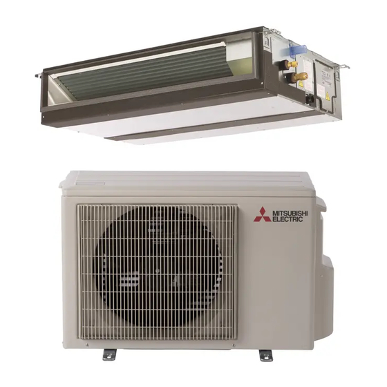
Air-Conditioners
PEAD-A09,12,15,18,24,30,36,42AA7
INSTALLATION MANUAL
For safe and correct use, please read this installation manual thoroughly before installing the air-conditioner unit.
MANUEL D'INSTALLATION
Veuillez lire le manuel d'installation en entier avant d'installer ce climatiseur pour éviter tout accident et vous
assurer d'une utilisation correcte.
FOR INSTALLER
POUR L'INSTALLATEUR
English
Français
Advertisement
Table of Contents

Related Manuals for Mitsubishi Electric Mr.Slim PEAD-A09AA7


Summary of Contents for Mitsubishi Electric Mr.Slim PEAD-A09AA7
- Page 1 Air-Conditioners PEAD-A09,12,15,18,24,30,36,42AA7 INSTALLATION MANUAL FOR INSTALLER English For safe and correct use, please read this installation manual thoroughly before installing the air-conditioner unit. MANUEL D’INSTALLATION POUR L’INSTALLATEUR Français Veuillez lire le manuel d’installation en entier avant d’installer ce climatiseur pour éviter tout accident et vous assurer d’une utilisation correcte.
- Page 2 [Fig. 3-2-1] [Fig. 3-2-2] (Unit: mm [in]) (Viewed from the direction of the arrow A) 700 [27- 9/16 [17- 475 [18- 100~200 ]~[7- 15/16 50~150 [2]~[5- 450 [17- 15/16 [Fig. 3-2-3] [Fig. 3-2-4] (Viewed from the direction of the arrow B) 50 [2] 700 [27- 9/16...
- Page 3 [Fig. 4-1-1] Center of gravity [Fig. 5-1-1] [Fig. 5-1-2] Unit body Nuts (field supply) Lifting machine Washers (accessory) M10 hanging bolt (field supply) [Fig. 6-1-1] øB (Unit: mm [in]) øA Model ø9.52 [3/8] ø6.35 [1/4] PEAD-A09AA7 ø12.7 [1/2] ø6.35 [1/4] PEAD-A12, 15, 18AA7 Indoor unit ø15.88 [5/8]...
- Page 4 (Unit: mm [in]) [Fig. 6-3-1] [Fig. 6-3-2] [25/32] [25/32] [25/32] [25/32] Pipe cover (small) (accessory) Pipe cover (large) (accessory) Caution: Thermal insulation (field supply) Pull out the thermal insulation on the refrigerant piping at the site, Pull insert the flare nut to flare the end, and replace the insulation in its Flare nut original position.
- Page 5 [Fig. 6-6-1] Insert pump's end 2 to 4 cm [13/16 to 1-5/8 in]. Remove the water supply port. About 2500 cc Water Filling port Screw [Fig. 7-0-1] [Fig. 7-0-2] <A> In case of rear inlet Duct Air inlet Access door Canvas duct Ceiling surfas Air outlet...
- Page 6 [Fig. 8-2-1] [Fig. 8-2-2] Terminal box Knockout hole Screw holding cover (1pc) Remove Cover [Fig. 8-2-3] [Fig. 8-2-4] Use PG bushing to keep the weight of the cable and external force from being Terminal block for power source and indoor transmission applied to the power supply terminal connector.
- Page 7 [Fig. 8-4-1] Service menu Function setting Function setting Test run Ref. address Grp. Ref. address Input maintenance info. Unit No. Mode 1 Grp./1/2/3/4/All Function setting Mode 2 Check Mode 3 Self check Mode 4 Main menu: Request: Monitor: Cursor Cursor Address Cursor Cursor...
- Page 8 [Fig. 10-0-1] [Fig. 10-0-2] [Fig. 10-0-3] Smooth maintenance Smooth maintenance Check menu Ref.address Ref. address Cool Error history Stable mode COMP. current Refrigerant volume check Cool / Heat/ Normal COMP. run time Refrigerant leak check times COMP. On / Off Smooth maintenance COMP.
-
Page 12: Refrigerant Piping Work
6. Refrigerant piping work Cautions On Refrigerant Piping • Do not put the end of the drain piping in any drain where ionic gases are generated. Be sure to use non-oxidative brazing for brazing to ensure that no foreign [Fig. -
Page 13: Electrical Work
7. Duct work • Connect canvas duct between unit and duct. [Fig. 7-0-1] (P.5) 4. Fit filter to the underside of the body. • Use incombustible material for duct parts. (Be careful of which side of the filter to fit.) [Fig. 7-0-4] (P.5) •... -
Page 14: Remote Controller
8. Electrical work • Perform wiring as shown in the diagram to the lower left. (Procure the cable locally.) • Use the [F1] or [F2] button to move the cursor to select the mode number, and Make sure to use cables of the correct polarity only. change the setting number with the [F3] or [F4] button to switch the setting [Fig. -
Page 15: Before Test Run
8. Electrical work Function table 1 Select unit number 00 Mode Settings Mode no. Setting no. Initial setting Check Not available Power failure automatic recovery *1*2 (AUTO RESTART FUNCTION) Available Indoor unit operating average Indoor temperature detecting Set by indoor unit’s remote controller Remote controller’s internal sensor Not Supported LOSSNAY connectivity... - Page 16 9. Test run 9.2. Test run 9.2.1. Using wired remote controller Make sure to read operation manual before test run. (Especially items to secure safety) Step 1 Turn on the power. • Remote controller: The system will go into startup mode, and the remote controller power lamp (green) and “PLEASE WAIT” will blink. While the lamp and message are blinking, the remote controller cannot be operated.
- Page 17 9. Test run 9.3. Self-check Refer to the installation manual that comes with each remote controller for details. RF thermostat is not established. • Refer to the following tables for details on the check codes. (Wireless remote controller) [Output pattern A] Beeper sounds Beep...
-
Page 18: Easy Maintenance Function
9. Test run • On IR wireless remote controller The continuous buzzer sounds from receiving section of indoor unit. Blink of operation lamp • On wired remote controller Check code displayed on the LCD. • If the unit cannot be operated properly after the above test run has been performed, refer to the following table to remove the cause. Symptom Cause Wired remote controller... -
Page 23: Mise En Place Des Tuyaux De Réfrigérant
6. Mise en place des tuyaux de réfrigérant 6.3. Connexion des tuyaux [Fig. 6-3-1] (P.4) Vérifier le vide avec la soupape multiple de manomètre, puis fermer la soupape • Appliquer une fine couche d’huile de réfrigérant sur la surface du siège de multiple de manomètre, et arrêter la pompe à... -
Page 24: Confirmation Des Décharges D'écoulement
6. Mise en place des tuyaux de réfrigérant 6.6. Confirmation des décharges d’écoulement 1. Insérer le tuyau d’écoulement (accessoire) dans l’ouverture d’écoulement (marge d’insertion : 25 mm [1 in]). (Ne pas cintrer le tuyau au-delà de 45° pour éviter qu’il ... -
Page 26: Installations Électriques
8. Installations électriques 8.4. Réglage des fonctions rieurs raccordés, lorsque ces appareils fonctionnent ensemble, sélectionner un numéro d’appareil 01 à 04. 8.4.1. Réglage des fonctions sur l’appareil (Sélection des fonctions Pour spécifier tous les appareils intérieurs parmi deux, trois ou quatre appareils de l’appareil) intérieurs raccordés lorsque ces appareils fonctionnent ensemble, sélectionner AL. -
Page 28: Marche D'essai
9. Marche d’essai Étape 2 Placez la télécommande sur “Test run” (Test fonctions). 1 Dans le Menu SAV, sélectionnez “Test run” (Test fonctions) puis appuyez sur le bouton [CHOIX]. [Fig. 9-2-1] (P.7) 2 Dans le Menu test de fonctionnement, sélectionnez “Test run” (Test fonctions) puis appuyez sur le bouton [CHOIX]. [Fig. 9-2-2] (P.7) 3 Le test fonctions démarre et l’écran Test fonctions s’affiche. - Page 29 9. Marche d’essai [Type de message A] Erreurs détectées par l’appareil intérieur Thermostat Télécommande sans fil radiofréquence de infrarouge télécommande à fil Symptôme Remarque Bips/Clignotement du témoin OPERATION INDICATOR Code de contrôle (Nombre de fois) Erreur de détecteur d’entrée d’air P2, P9 Erreur de détecteur de tuyau (liquide ou tuyau à...
-
Page 30: Fonction D'entretien Aisé
9. Marche d’essai • Si l’appareil ne fonctionne pas correctement après la marche d’essai ci-dessus, reportez-vous au tableau suivant pour résoudre le problème. Symptôme Cause Télécommande sans fil LED 1, 2 (CCI de l’appareil extérieur) Pendant les 2 minutes Après l’éclairage de la LED 1, 2, la LED 2 •... - Page 32 This product is designed and intended for use in the residential, commercial and light-industrial environment. Please be sure to put the contact address/telephone number on this manual before handing it to the customer. HEAD OFFICE: TOKYO BLDG., 2-7-3, MARUNOUCHI, CHIYODA-KU, TOKYO 100-8310, JAPAN KJ79F751H03...
Need help?
Do you have a question about the Mr.Slim PEAD-A09AA7 and is the answer not in the manual?
Questions and answers