Table of Contents
Advertisement
Quick Links
Advertisement
Table of Contents

Summary of Contents for Hornady Lock-N-Load
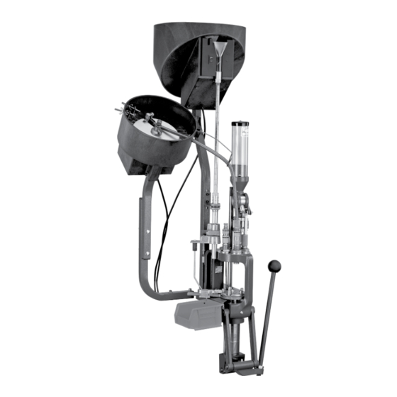
- Page 1 INSTRUCTIONS Lock-N-Load ® Powder Measure and Case Activated Powder Drop...
- Page 2 Hornady One Shot Gun Cleaner and Lube. ® ® TABLE OF CONTENTS Lock-N-Load Powder Measure Overview......................1 Bill of Materials of Lock-N-Load Powder Measure ........3 Exploded View of Lock-N-Load Powder Measure ........4 Disassemble......................7 Assemble ......................8 Operate and Adjustment ...................8 Precautions ......................9...
-
Page 3: Table Of Contents
Lock-N-Load bushings. (You can remove and change Hornady powder ® measures with a quick turn, without changing adjustments.) The Case Activated Powder Drop unit can be used ONLY on the Hornady Lock-N-Load Powder ® Measure. Before using, disassemble and carefully clean the inside surfaces of the drop tube, measure adapter and powder sleeves. - Page 4 POWDER MEASURE BILL OF MATERIALS Production Part Item No. Qty. Description Number 392740 POWDER MEASURE BODY 392741 ROTOR 392743 PLUNGER 392742 SLEEVE, ADJUSTING 392744 BUTTON 392748 C-CLIP, FOR 5/32" O.D. 392752 HANDLE 392719 BHCS, 10-32 x 3/8 390200 SOCKET HEAD CAP SCREW 5-40 X 3/8" 044000 LOCK RING 398520...
- Page 5 POWDER MEASURE EXPLODED VIEW...
-
Page 6: Bill Of Materials For Case Activated Powder Drop
CASE ACTIVATED POWDER DROP (CAPD) BILL OF MATERIALS Item No. Production Part Number Qty. Description 392721 BHSCS 10-32 X 1.00 392708 MOUNTING CLAMP 392710 ROTOR ARM 392719 BHSCS 10-32 X 3/8 392715 SHOULDER NUT 398735 PIVOT 398737 DRIVE LINK 398736 MEASURE LINK 398742 BHSCS 10-32 X 1.25... -
Page 7: Exploded View For Case Activated Powder Drop
CAPD EXPLODED VIEW... - Page 8 Rotor while it is out of the Body. • Remove the Lock Nut, O-Ring and Sleeve from the Metering Plunger. Spray all metal parts liberally with Hornady One Rotor Body Shot Gun Cleaner and Lube. Be sure all rust preventatives are removed (Fig. 4).
- Page 9 To Re-assemble after cleaning: Reverse the procedure described on the previous page. The Rotor and Body are very closely fit and must be properly aligned to reassemble. NOTE: Make sure the rotor is inserted with the push button on the left (assuming powder dispenser body is facing you).
- Page 10 If you allow the Handle to fall while changing units, you will drain the Hopper. • Be sure you have the proper Lock-N-Load device locked in place, before operating. • Always verify your charges with a scale before loading.
-
Page 11: Assembling The Case Activated Powder Drop Rotor Arm
• Attach the Case Activated Powder Drop Rotor Arm (3) to the right side of the Rotor using two Button Head Cap Screws (4). Lock-N-Load Upper Bracket Assembly Powder Measure • Slide the Upper Bracket Assembly onto the Powder Measure. -
Page 12: Drop Tube Installation
Drop Tube Installation • Screw the Drop Tube into the bottom of the Powder Measure. • Lubricate the exterior of the Drop Tube with Hornady One Shot Gun Cleaner and Lube or other similar dry lubricant. Lock-N-Load Powder Measure Rotor... -
Page 13: Installing The Case Activated Powder Drop (Lower Assembly)
• Select the appropriate powder bushing sleeve for your application. (Each sleeve has a shallow countersink on Lock-N-Load one side, and a deep counter sink on Bushing the other.) Insert the bushing, with the deep counter sink facing up, into the top of the measure adapter. -
Page 14: Final Powder Measure Assembly
Final Powder Measure Assembly • Insert the Powder Drop Tube into the Link Arm lower assembly • Connect the Link Arm (8) to Lower Assembly by sliding the Link over the Thumb Screw (23). • Tighten the Thumb Screw. Refer to the CAPD Bill of Materials on page 5 for Thumb Screw part numbers. -
Page 15: Case Activated Powder Drop Adjustment
Case Activated Powder Drop Adjustments Insert a case into the shell plate at station 3 of your Lock-N-Load AP and operate the handle to raise the ram to its highest position. (Refer to your Lock-N-Load AP manual) Lower the Powder Measure by rotating it clockwise into the press until the Powder Measure Rotor is fully rotated, but not contacting the end of the slot in the Powder Measure Body. - Page 16 (2) has been altered or repairs have been made or attempted by other than authorized factory personnel; (3) is used commercially; or (4) has been altered or defaced in any way. This warranty supersedes all other warranties for Hornady products either written or ®...


Need help?
Do you have a question about the Lock-N-Load and is the answer not in the manual?
Questions and answers