Table of Contents
Advertisement
Advertisement
Table of Contents

Subscribe to Our Youtube Channel
Related Manuals for Hornady Lock-N-Load 366 Auto


Summary of Contents for Hornady Lock-N-Load 366 Auto
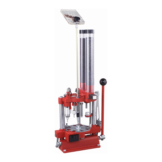
- Page 1 OPERATION MANUAL Lock-N-Load 366 Auto ® ™ Automatic Shotshell Reloader...
-
Page 2: Table Of Contents
TABLE OF CONTENTS Steps: Page List of Illustrations: Page Overview . . . . . . . . . . . . . . . . . . . . . . . . . . . . . . . . . . . . . . .3 Function and Adjustment . -
Page 3: Overview
Hornady’s Reloading Advisory Center . station . If you are unable to correct the problem, please write IMPORTANT: Never mix powders or use unidentified powder. -
Page 4: Setting Up Your 366 Auto
SETTING UP YOUR 366 AUTO Mount your 366 Auto securely toward the front of a sturdy Reinstall the bushings and push the charge bar back bench . All operations of the press are to a full stop, so the in place . If the powder slide should drop out of the operating handle must clear the bench when in the down measure assembly, do not disassemble the measure position . -
Page 5: Function And Adjustment
FUNCTION AND ADJUSTMENT The following is a detailed description of the operation and Fig. 1: Function and Adjustment adjustment of the 366 Auto Reloading Press . This press has been pre-adjusted at the factory for Remington STS cases, but every person has a preference about how the finished product should look, so some changes might be necessary . -
Page 6: Resize And De-Prime (Station 1A)
STEP 1: STATION 1A (RESIZE AND DEPRIME) Place an empty shell in Station 1A, making sure the deprime Fig. 2: Resize and De-Prime punch enters the case mouth and the shell is reasonably centered under the size die (14) . Pull the operating handle (37) to the bottom of the stroke . -
Page 7: Prime Only (Station 1)
STEP 2: STATION ONE (DE-PRIME ONLY) Insert the case in station. Fig. 3: De-Prime 1 . Normally, at this time, we would fill the primer tube (2), but since we are working with a single shell, drop only one primer from the tray (1) into the primer tube (2) . -
Page 8: Prime (Station 2)
STEP 3: STATION TWO (PRIME) Pull the handle (37) through a complete stroke . The primer Fig. 4: Prime seating punch (20) or the optional spring loaded primer seater punch (010051) will enter the case and push the case down, over the primer in the primer seating pad (3) . -
Page 9: Powder Drop (Station 3)
STEP 4: STATION THREE (DROP POWDER) Before pulling the handle (37), pull the powder slide (69) toward Fig. 5: Powder Drop you . The spring (71) will lock the slide in place in the second slot of powder slide (69) . The powder drop is now on . -
Page 10: Wad Seating (Station 4)
STEP 5: STATION FOUR (WAD SEATING) Insert a wad in the wad guide (106A) . Pull the operating handle Fig. 6: Wad Seating (37) through a complete stroke . When the handle (37) is pulled, the spring (106B) around the wad guide rod (105) turns the wad guide bracket (101) to align the wad with the case . -
Page 11: Shot Drop (Station 5)
STEP 6: STATION FIVE (SHOT DROP) Before pulling the handle (37), rotate the shot shut-off (70) Fig. 7: Shot Drop backward, turning on the shot . Now, lower the handle (37) . The shot drop tube (47) enters the case mouth and then both case and shot drop tube (47) rise together to the top of the stroke . -
Page 12: Crimp Starter (Station 6)
. A hole in the case mouth of ¼" should be left when the shell completes this station. Hornady loaders come with eight point crimp starter installed, but if you are using another crimp, substitute with either smooth for paper or six point plastic, included with your loader . -
Page 13: Crimp (Station 7)
STEP 8: STATION SEVEN (CRIMP) Fig. 9: Crimp As you pull the handle (37), the shell in Station Seven will enter Magic and Federal Gold Metal Cases, eleven to thirteen threads the crimp die (59) . The shell will contact the inside of the die should be exposed . -
Page 14: Crimp Taper (Station 8)
STEP 9: STATION EIGHT (TAPER CRIMP) Fig. 10: Taper Crimp The taper crimp is a smooth crimp starter (82) and will taper the At this point in a normal reloading sequence, you would have finished case better than factory loads . As the shell at Station a completed shell at each station . -
Page 15: Adjustment Of Auto Advance
ADJUSTMENT OF AUTO ADVANCE When the operating handle (37) is pulled all the way up, a Fig. 11: Adjustment of Auto Advance spring (98) swings the pivot arm (85) and the advance pawl (94) to your right . The hook of the pawl rides in the gap between the shell plate (45) and the shell plate ring (110) . -
Page 16: Troubleshooting
TROUBLESHOOTING 1 . Check to see the loader is mounted near the front of the bench, allowing the handle (37) to come completely down . 2 . Check to see if the size die body (14) adjustment has changed or if the size die ring cap (19) has loosened . 3 . - Page 17 1 . Check your operation of the tool, making sure you allow enough time for the wad Wads are not to correctly align with the ram . The wad guide (106) should be set to swing out just seating properly, far enough for easy insertion of the wad;...
-
Page 18: Converting To Another Gauge
. Adjust the wad ram substantial changes in pressure . Hornady Manufacturing (46) to provide best crimp (except as noted in sinking crimps or Company has no control over the components and equipment bulging) . -
Page 19: Powder Bushings
POWDER BUSHING CHART 266 318 363 330 366 345 363 390 354 291 333 372 366 303 300 345 426 390 354 309 324 414 390 438 420 381 393 357 438 429 402 366 291 396 318 330 330 336 420 429 402 381 402 423 453 435 393 363 450... -
Page 21: Bill Of Materials
BILL OF MATERIAL Item # Part # Description Item # Part # Description 390132 12/16 ga . Powder Drop Tube 020003 Assembly 390144 20 Ga . Powder Drop Tube 480032 Movable Lid 390156 410/28 Ga . Powder Drop Tube 398415 Panhead Screw 390133 12/16 ga . - Page 22 BILL OF MATERIAL (continued) AUTO-ADVANCE PARTS SHELL DROP PARTS Item # Part # Description Item # Part # Description 050034 Auto-Advance Assembly 050035 Shell Drop Assembly (factory installed) 050041 Pawl Assembly 190046 Platen 190043 Pivot Arm 392052 Shell Chute 380100 SAME AS 12 390182 Chute Screw 6-32 x 1/4 Pan Head...
- Page 23 190101 FIELD LOAD BUSHINGS For use with all Hornady shotshell reloaders. Compensates for the tighter packing of small shot sizes. calibarted to measure maximum legal loads for trap and skeet shoting. These loads are designed for use with lead shot only.
- Page 24 P .O . Box 1848, Grand Island, NE 68802-1848 308-382-1390 • 800-338-3220 • Fax: 308-382-5761 www .hornady .com • Hornady .com/contact_us 18HMC0090 | 06/2018 T366...
Need help?
Do you have a question about the Lock-N-Load 366 Auto and is the answer not in the manual?
Questions and answers