Table of Contents
Advertisement
Advertisement
Table of Contents

Related Manuals for UNI-T UDP3305S Series


Summary of Contents for UNI-T UDP3305S Series
- Page 1 UDP3305S Series Programmable DC Power Supply User Manual...
-
Page 2: Limited Warranty And Liability
If the original purchaser sells or transfers the product to a third party within one year from the date of purchase of the product, the warranty period of one year shall be from the date of the original purchase from UNI-T or an authorized UNl-T distributor. -
Page 3: Safety Information
UNI-T, pay the shipping cost, and provide a copy of the purchase receipt of the original purchaser. If the products is shipped domestically to the purchase receipt of the original purchaser. If the product is shipped to the location of the UNI-T service center, UNI-T shall pay the return shipping fee. -
Page 4: Operating Voltage
UDP3305S Series Programmable DC Power Supply User Manual personal injury and property losses caused by the user's failure to comply with the following terms. Correct connection of ground wire To avoid electric shock, please use the provided cable to connect and make sure that the product is properly grounded before use. -
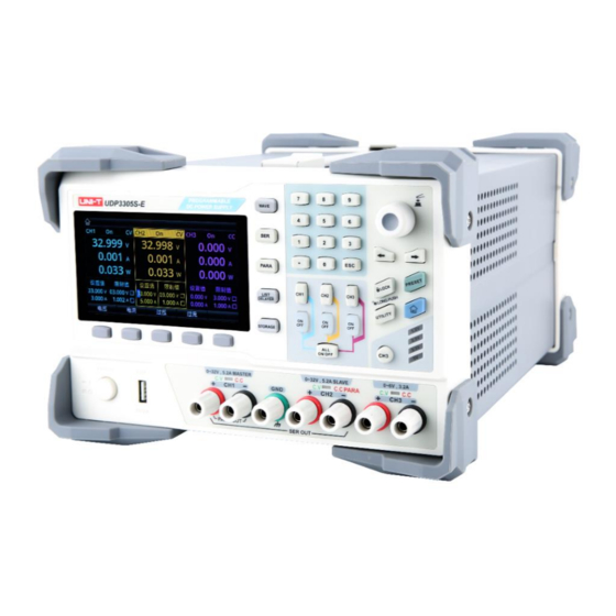
Page 5: Product Overview
Product Series (Features and Specifications) Front Panel Rear Panel 3.11 Product Series UDP3305S series programmable DC power supply includes two models: UDP3305S and UDP3305S-E. The output ranges are shown in the table below: Maximum output current Model Maximum output voltage CH1: 33V CH1: 5.2A... -
Page 6: Specifications
UDP3305S Series Programmable DC Power Supply User Manual Four-channel independent output: CH1/CH2: 0~30V/5A, CH3: 0~6V/3A, CH4: 5V/2A (USB) Multi-protection: over voltage/over current/over temperature protection CH1/CH2/CH3 independent output switch Excellent load regulation and line regulation Ultra-low output ripple and noise ... - Page 7 UDP3305S Series Programmable DC Power Supply User Manual Command processing <100ms <100ms time Adjustable continuously from 0 to Adjustable continuously from 0 to Output range rated voltage rated voltage Power supply regulation: Power supply regulation: Regulation ≤0.01%+250μA ≤0.01%+250μA Load regulation: ≤0.01%+250μA Load regulation: ≤0.01%+250μA...
- Page 8 UDP3305S Series Programmable DC Power Supply User Manual Rise: full load<50ms; no-load< Rise: full load<50ms; no-load< 30ms 30ms Fall: full load<45ms; no-load< Fall: full load<45ms; no-load< 400ms 400ms Voltage Rise: full load<50ms; no-load< Rise: full load<50ms; no-load< programmed 30ms 30ms...
-
Page 9: Front Panel
UDP3305S Series Programmable DC Power Supply User Manual 3.12 Front Panel 1.2.1 Keys Function WAVE Enable the waveform display function... -
Page 10: Multi-Function
UDP3305S Series Programmable DC Power Supply User Manual Enable or disable the series connection function PARA Enable or disable the parallel connection function LIST/DELAYER Enable and switch between list mode or delayer STORAGE Internal and external storage and recall Numeric keys... -
Page 11: Rear Panel
UDP3305S Series Programmable DC Power Supply User Manual 3.13 Rear Panel Inspection and Installation This chapter includes: Packing List Requirements for Power Supply Operating Environment Cleaning 3.11 Packing List Before using the instrument: 1. Check whether the appearance of the product is damaged, scratched or has other defects;... -
Page 12: Requirements For Power Supply
Warning: Please do not use the damaged power cord. 3.13 Operating Environment UDP3305S series can only be used in normal temperature and low condensing zone. The general environment requirements are listed as follows. Environment Requirements Operating temperature 0°C~40°C... -
Page 13: Preparation For Start-Up
UDP3305S Series Programmable DC Power Supply User Manual 3. Preparation for Start-Up This chapter includes: Power on and Run Output Terminals User Interface Power on and Run Before connecting the power supply, make sure that the power supply voltage switch on the rear panel is consistent with the actual connected voltage, and the frequency is 50Hz or 60Hz. -
Page 14: Front Panel Operations
System Settings Constant Voltage Output UDP3305S series power supply provides two output modes: constant voltage output (CV) and constant current output (CC). In CV mode, the output voltage equals the voltage setting value and the output current is determined by the load. In CC mode, the output current equals the current setting value and the output voltage is determined... -
Page 15: Setting Interface
UDP3305S Series Programmable DC Power Supply User Manual the power supply is in constant current mode). This section introduces the operation method in constant voltage output mode. Setting Interface Operation steps: 1. Press the power switch to power on the instrument. -
Page 16: Constant Current Output
" to realize the connections, but it is limited to the series and parallel connections between CH1 and CH2. If users need to connect the UDP3305S series power supply in series and parallel with other power supply channels, they can only realize it through external wiring, as shown in the figure below, but pay attention to the following... -
Page 17: Power Supply Series Connection
Higher voltages can be provided by connecting power supplies in series. In this case, the output voltage is the sum of the output voltages of all the channels. When the UDP3305S series power supply enters the series mode, users only need to set its output voltage, output current, and the overvoltage and overcurrent protection values. - Page 18 High currents can be provided by connecting power supplies in parallel. In this case, the output current is the sum of the output currents of all the channels. When the UDP3305S series power supply enters the parallel mode, users only need to set its output voltage, output current, and the overvoltage and overcurrent protection values.
- Page 19 List Mode (Timer) and Delayer UDP3305S series power supply provides the timer and delayer functions. When the timer is enabled, the instrument outputs the preset parameter groups (at most 2048 groups): voltage, current and timing time.
- Page 20 UDP3305S Series Programmable DC Power Supply User Manual The interface of list mode is as follows: To set the list mode parameters manually: Press “Basic parameter” key to enter the setting interface. Users can edit the starting group number, the required number of output groups (maximum 2048 groups), the number of cycles (maximum 99999 times) and the output status after the timing time expires.
- Page 21 UDP3305S Series Programmable DC Power Supply User Manual Delayer Parameter Setting The interface of delayer is as follows: To set the delayer parameters manually: Press “Basic parameter” key to enter the setting interface. Users can edit the starting group number, the required number of output groups (maximum 2048 groups), the number of cycles (maximum 99999 times), and conditions for terminating the output state and stopping the delayer.
- Page 22 UDP3305S Series Programmable DC Power Supply User Manual The list mode and delayer are equipped with multiple output templates. The purpose is to facilitate users to operate and save time. The following sections describe the parameters of each template. List Mode Templates The optional list mode templates include: sine, pulse, ramp, stair up, stair down, stair up down, exponential rise and exponential fall.
- Page 23 UDP3305S Series Programmable DC Power Supply User Manual 4. Stair Up The Stair Up waveform is as shown in the figure below. The instrument determines the amplitude of the Ramp according to the maximum and minimum currently set. The total number of points (N) will divide the amplitude into N-1 steps.
- Page 24 UDP3305S Series Programmable DC Power Supply User Manual Exponential rise 8. Exponential Fall The Exponential Fall waveform is as shown in the figure below. The instrument determines the amplitude of the waveform according to the maximum (M) and minimum (N) currently set and determines the waveform period according to the total number of points (P) and the time interval (maximum 99999).
- Page 25 UDP3305S Series Programmable DC Power Supply User Manual Save and Read the Timer/Delay File Users can store the timer/delay parameters edited manually or using the template in internal or external memory and recall them when required. Save The instrument can store 10 groups of setting values of the three functions of list mode, delayer and state file respectively, and also supports external storage.
-
Page 26: Waveform Display
File read interface Waveform Display UDP3305S series power supply has waveform display function, which can display the output voltage, current and power of each channel on the screen. When each channel operates independently, voltage, current and power waveforms of three channels can be... - Page 27 4.10 Preset UDP3305S series power supply provides 5 sets of output presets that can be freely edited and stored. Users can set the voltage, current, limit voltage and limit current parameters of each channel and series and parallel channel in advance, and load the parameters when using, so as to avoid the step of resetting parameters every time when turning on the instrument.
- Page 28 UDP3305S Series Programmable DC Power Supply User Manual Preset interfere Operation steps: 1. Press the power switch to power on the instrument. 2. Press to enter the preset interface. 3. Select a preset group: Rotate the knob or press to switch between the preset groups. Press the Edit key or the knob to select a preset group and enter its editing interface.
-
Page 29: Trigger Input
UDP3305S Series Programmable DC Power Supply User Manual Press , select “Monitor”, and then press the “Enter” key or the knob to enter the monitor setting interface. 3. Select the monitor channel and set the parameters: Select a channel and connect the load. -
Page 30: System Settings
UDP3305S Series Programmable DC Power Supply User Manual Operation steps: 1. Connect the digital I/O interface on the rear panel to the external trigger source. 2. Press the power switch to power on the instrument. 3. Enter the trigger interface: Press , select “Trigger”, and then press the “Enter”... - Page 31 UDP3305S Series Programmable DC Power Supply User Manual System software version...
Need help?
Do you have a question about the UDP3305S Series and is the answer not in the manual?
Questions and answers