Table of Contents
Advertisement
Quick Links
NOTICE!
No mixing valve will work satisfactorily if improperly installed. We suggest, therefore, that you read
these instructions carefully before installing and follow directions as outlined. Handle the mixing valve with care.
CAUTION: When maintaining and adjusting the
mixing valve, all fixtures should be isolated from
use. Lawler Manufacturing Co., Inc. recommends
that you work safely at all times and in a manner
consistent with the OSHA Lock/Tagout standard,
29 CFR 1910.147 and other applicable standards.
This installation & maintenance manual covers all
configurations of the Series 66.
B
A
C
ASSE 1017 Approved
ASSE Lead Free Certified
Certified to CSA B125.3
INSTALLATION &
Maintenance MANUAL
A
Design and specifications subject to change without notice.
Please refer to temperedwater.com to ensure most
current data sheet and other design solutions.
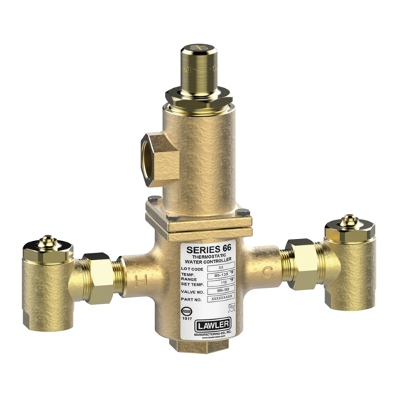
Series 66
Thermostatic Water
Controller
CAPACITIES – GPM SERIES 66
Pressure Drop PSI
5
Valve Number
66-25
9
66-50
18
66-80
28
66-125*
43
66-150*
52
66-200*
64
1/2 gpm when properly installed in recirculated system.
CAPACITIES – LPM SERIES 66
Pressure Drop PSI
5
Valve Number
66-25
34
66-50
68
66-80
106
66-125*
163
66-150*
197
66-200*
242
*66-125, 66-150 and 66-200 are not lead free certified
DIMENSIONS
Valve Number
A N.P.T.
66-25
3/4"
66-50
3/4"
66-80
1"
66-125*
1-1/4"
66-150*
1-1/2"
66-200*
2"
Dimensions are for reference purposes only. For rough-in dimensions
please refer to Lawler's Revit/BIM models found at temperedwater.com.
*66-125, 66-150 and 66-200 are not lead free certified
temperedwater.com
5330 East 25 th St.
Indianapolis, IN 46218
Phone (317) 261-1212
Fax (317) 261-1208
10
20
30
45
60
Capacity – GPM
12
17
21
25
28
25
34
41
50
57
39
54
66
80
91
60
85
103
125
144
72
100
124
150
174
96
133
165
200
230
10
20
30
45
60
Capacity – LPM
45
64
79
94
106
95
129
155
189
216
148
204
250
303
344
227
322
390
473
545
273
379
469
568
659
363
503
625
757
871
B N.P.T.
C
3/4"
10"
1"
10"
1-1/4"
11"
1-1/2"
12-3/4"
2"
13-1/4"
2"
15"
temperedwater.com/patents
Min.
Flow
GPM
4
8
12
19
23
30
Min.
Flow
LPM
15
30
45
72
87
114
M 66 E
Advertisement
Table of Contents

Subscribe to Our Youtube Channel
Related Manuals for Lawler 66 Series


Summary of Contents for Lawler 66 Series
- Page 1 2” 2” 15” Dimensions are for reference purposes only. For rough-in dimensions please refer to Lawler’s Revit/BIM models found at temperedwater.com. *66-125, 66-150 and 66-200 are not lead free certified temperedwater.com/patents ASSE 1017 Approved Design and specifications subject to change without notice.
- Page 2 Performance Checking Hot Water Shut-Off The Series 66 water temperature controller is carefully Allow full hot and cold water to flow through the valve for assembled and tested at the factory to mix hot and cold one minute. Shut off the cold water stop and check valve water to any desired temperature within range.
- Page 3 Series 66 Cut-away Figure A 1. Place a 3/8” wooden dowel See Fig. B rod into center of thermostat then place in 85°F water. Make a reference REFERENCE mark on the rod as MARKS shown in fig. A. 2. Now insert thermostat into hot water that is at least See Fig.
- Page 4 GUARANTEE We guarantee the Lawler Mixing Valve to be free from def ects in workmanship and material, and for a period of one year from date of purchase, will replace any parts found by us to be defective. We will not be held responsible, however, for any labor incidental to, or for any damages caused by defective material.
Need help?
Do you have a question about the 66 Series and is the answer not in the manual?
Questions and answers