Table of Contents
Advertisement
Quick Links
5330 East 25
Street
th
Indianapolis, Indiana 46218
Phone (317) 261-1212
Fax (317) 261-1208
Thermostatic Water Controllers will not work satisfactorily if improperly installed.
Read these instructions carefully before installing and follow directions as outlined.
A
C
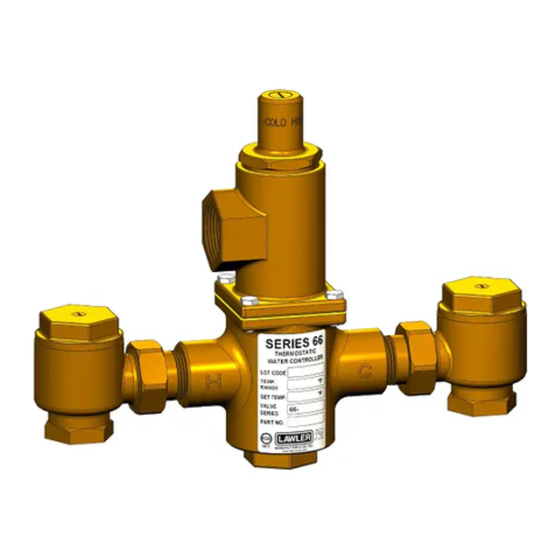
General Description
The Series 66 water temperature controller is care-
fully assembled and tested at the factory to mix hot
and cold water to any desired temperature within
range. The temperature of the hot water should be
at least 20°F higher than the maximum valve setting.
The major safety features are:
1. Failure of cold water supply causes the hot water
ports to reduce hot water flow.
2. Failure of hot water supply causes the cold water
ports to reduce cold water flow.
3. Failure of the thermostat allows both ports to
reduce flow of hot and cold water.
At each inlet of the controller is a union end stop
and check valve with removable strainer. Stop and
check valves prevent water from bypassing between
the hot and cold water supply lines. These valves
should be fully open when in operation.
Maximum Inlet Conditions
Pressure: 125 psi
Temperature: 200°F
Maintenance
The controller should be checked periodically and,
if needed, cleaned as outlined in "INSPECTION and
CLEANING VALVE." To test for proper setting and
operation - proceed as follows:
1. Turn on full hot and cold water to the valve. The
mixing valve should deliver water at the outlet
temperature stamped on the label. Standard
setting is 110°F. If the outlet temperature is differ-
ent than that shown on the label, readjust valve
www.lawlervalve.com
Series 66
NOTICE!
B
A
ASSE 1017 Approved
DIMENSIONS:
Pressure Drop PSI
Valve Number
66-25
66-50
66-80
66-125
66-150
66-200
according to "TEMPERATURE ADJUSTMENT"
procedure on page 2.
2. If after adjusting the outlet temperature the
water stays below the set temperature, see
"CHECKING COLD WATER SHUT-OFF." If the
temperature stays above the set temperature,
see "CHECKING HOT WATER SHUT-OFF."
Caution: When maintaining and adjusting the
mixing valve, all fixtures should be isolated from
use.
Lawler Manufacturing Co., Inc. recommends
that you work safely at all times and in a manner
consistent with the OSHA Lock/Tagout standard,
29 CFR 1910.147 and other applicable standards.
Checking Cold Water Shut-Off
Turn on full hot and cold water supply to the valve,
then shut off the hot water stop and check valve
only. Cold water should flow through the controller
momentarily then be reduced to a negligible amount.
Failure to do so indicates that:
a. Plunger is sticking and requires cleaning or
replacement.
(1)
Installation &
Maintenance Manual
Certified to
CSA B125.3
A
B
Valve No. N.P.T. N.P.T. C
66-25
/
/
10"
3
"
3
"
4
4
66-50
/
1"
10"
3
"
4
66-80
1" 1
/
" 11"
1
4
66-125 1
/
" 1
/
" 12
/
1
1
3
"
4
2
4
66-150 1
/
" 2" 13
/
1
1
"
2
4
66-200
2"
2"
15"
CAPACITIES
5
10
20
30
45
Capacity-GPM
9
12
17
21
25
18
25
34
41
50
28
39
54
66
80
43
60
85
103 125 144 165
52
72
100 124 150 174 193
64
96
133 165 200 230 265
M66 N
U P
C
C
®
60
80
28
32
57
65
91
103
Advertisement
Table of Contents

Related Manuals for Lawler 66-25


Summary of Contents for Lawler 66-25
- Page 1 Maximum Inlet Conditions mixing valve, all fixtures should be isolated from Pressure: 125 psi use. Lawler Manufacturing Co., Inc. recommends Temperature: 200°F that you work safely at all times and in a manner consistent with the OSHA Lock/Tagout standard, Maintenance 29 CFR 1910.147 and other applicable standards.
- Page 2 Checking Cold Water Shut-Off (Cont.) Figure A 1. Place a ″ wooden dowel b. Spring #13 has lost its strength and should rod into center of thermo- be replaced. stat then place in 85°F water. Make a reference Note: Lack of water flow can be normal on the first mark on the rod as shown test if the temperature of the cold water is in fig.
- Page 3 Series 66 Repair Parts Item Description Part No. Screw 7628-00 Adjusting Screw 8737-00 Bonnet Gasket See Fig. B Series 66 cut-away Dome — Liner O-Ring Liner Plunger/ Piston Liner Assembly Figure C* Valve Spring — Bottom Plug — Pusher O-Ring Bonnet See Fig.
- Page 4 GuARANTEE We guarantee the Lawler Mixing Valve to be free from held responsible, however, for any labor incidental def ects in workmanship and material, and for a pe-...
Need help?
Do you have a question about the 66-25 and is the answer not in the manual?
Questions and answers