Table of Contents
Advertisement
Quick Links
KPC - 9612 Plus
Users Guide:
Kantronics
1202 E. 23rd Street,
Lawrence, Kansas 66046
Orders/ Inquiries (913) 842-7745
FAX (913) 842-2031
e-mail sales@kantronics.com
website: www.kantronics.com
Service / Technical Support (913) 842-4476 (9-12 am, 2-5 pm Central Time,
M-F)
Introduction,
Getting Started,
Modes of Operation,
Command Reference, and
Hardware Specifications
FAX
(913) 842-2021
Advertisement
Table of Contents

Related Manuals for Kantronics KPC-9612 Plus


Summary of Contents for Kantronics KPC-9612 Plus
- Page 1 Modes of Operation, Command Reference, and Hardware Specifications Kantronics 1202 E. 23rd Street, Lawrence, Kansas 66046 Orders/ Inquiries (913) 842-7745 FAX (913) 842-2031 e-mail sales@kantronics.com website: www.kantronics.com Service / Technical Support (913) 842-4476 (9-12 am, 2-5 pm Central Time, M-F) (913) 842-2021...
- Page 2 1202 E. 23rd Street, Lawrence, KS 66046. © Copyright 1997 by Kantronics Co., Inc. All Rights Reserved. Contents of this publication or the firmware within the KPC-9612 Plus may not be reproduced in any form without the written permission of the copyright owner.
- Page 3 Please fill out this warranty registration form (or a copy of it) and mail it with a copy of your sales receipt to register your purchase. Both must be on file at Kantronics in order for you to receive warranty service. Refer to the warranty policy in this manual for further information.
- Page 4 User’s Guide KPC-9612 Plus v 8.2...
-
Page 5: License Agreement
WARE and accompanying written materials on a permanent basis provided you retain no copies and the recipient agrees to the terms of this Agreement. Kantronics may terminate this Agreement without notice if you violate any terms or conditions of the Agreement. In the event of termination of the Agreement, provisions relating to Kantronics’... - Page 6 (c)(1)(ii) of the Rights in Technical Data and Computer SOFTWARE clause of DFARS 252.227-7013. Kantronics may in its sole discretion, provide you with upgrades of the SOFT- WARE and/or Documentation if you have provided Kantronics your completed Warranty registration with a copy of your receipt showing the amount you paid.
-
Page 7: Table Of Contents
Alternatives to AX.25 ......26 Inside a TNC – the KPC-9612 Plus ......27 KPC-9612 Plus v 8.2... - Page 8 Table of Contents Installing Your KPC-9612 Plus ....... . 29 The Major Components of Your Station .
- Page 9 ALT+B = Holding Buffer: OPEN or CLOSE (Default) ... . . 80 ALT+C = Holding Buffer: CLEAR ..... . . 81 KPC-9612 Plus v 8.2 User’s Guide...
- Page 10 Getting Started ..........91 The Front Panel of the KPC-9612 Plus ..... . . 92 Beginning a Session .
- Page 11 Using Your PBBS ....... 123 KPC-9612 Plus v 8.2 User’s Guide...
- Page 12 Paging ........142 Introduction to Paging ......142 User’s Guide KPC-9612 Plus v 8.2...
- Page 13 GPS Equipment Requirements ......160 Cabling a GPS Unit to a Kantronics TNC ....161 Setup: Configuring a Kantronics TNC for GPS Operation .
- Page 14 Copying Weather Broadcasts NWS EMWIN ....189 Kantronics Host Mode Operation ..... . . 190 KISS Mode .
- Page 15 Applying Power through the DB-9 connector....290 Resetting the KPC-9612 Plus through the DB-9 connector..290 Port 2: High Speed (e.g., 9600 Baud) ..... 290 Port 2 (High Speed) Transmit level .
- Page 16 A/D Converter ........298 KPC-9612 Plus Jumpers ......298 Jumper Locations .
-
Page 17: Limited Warranty
2. REMEDY. Kantronics agrees that, for any Applicable Product found by Kantronics to be in violation of the warranty of Section 1 hereof within the Ap- plicable Warranty Period, it will, at its option, repair or replace the defective Ap- plicable Product at no charge to you, excluding in-bound shipping charges. -
Page 18: Applicable Products
Period”) are as follows: Applicable Products: UNITS: KPC-9612, KPC-9612 Plus, KAM, KAM Plus, KPC-3, KPC-3 Plus, rfc 2/70, rfc 2/70G, rfc 4-110, rfc 4-310, Mini-Amp 144, Mini-Amp 144P, Mini-Amp 440, Mini-Amp 440P, MAX-Amp 10, MAX-Amp 45. Applicable Warranty Period: One (1) year from date of purchase. - Page 19 If the dealer is unable to assist you, contact Kantronics Co., Inc., by mail at 1202 East 23rd Street, Law- rence, Kansas 66046 USA; by fax at 913-842-2021; or by phone at our Customer Support number 913-842-4476 (Hours: 9:00 a.m.
- Page 20 Limited Warranty shall be subject to a minimum charge of one-half hour labor rate and the product will be returned to you at your sole expense. Please note, no warranty service will be provided until Kantronics has been furnished with your Warranty Registration card and copy of proof of purchase establishing purchase date.
-
Page 21: Return/Repair Procedures
It may be useful to perform a “Hard Reset”. (See Hard Reset section.) If service or repairs still appear necessary after you have checked the items listed above, it may be wise to call, fax, e-mail or write Kantronics to determine if the problem can be solved without returning the unit. -
Page 22: Charges
Charges Consult the limited warranty policy in this manual for the service provisions of- fered by Kantronics at no charge. This warranty is considered to be in force only when the customer has submitted his completed warranty registration within 10 days of purchase, and when the stipulations of the warranty have been met. -
Page 23: International Returns
In case of unit problems, first contact the dealer from whom you purchased the product. If you must return a Kantronics product to us, please observe the steps outlined below. It will save both you, the customer, and Kantronics unnecessary difficulties and expense. - Page 24 To be eligible for repair under warranty, we must have a record that you sent your Warranty Registration card and proof of purchase to Kantronics, and the item(s) must still be within the warranty period at the time the return is authorized.
-
Page 25: Radio Frequency Interference Statement
The user is also cautioned that any peripheral device installed with this equip- ment must be connected with a high-quality shielded cable to insure compliance with FCC limits. KPC-9612 Plus v 8.2 User’s Guide... -
Page 26: Eu Declaration Of Conformity: "Ce
EU Declaration of Conformity: “CE” EU Declaration of Conformity: “CE” NOTE: This equipment, Kantronics’ KPC-9612 Plus, has been tested and found to comply with the essential emission and immunity requirements of the EMC Directive 89/336/EEC. The test results are on file at the corporate offices of Kantronics. -
Page 27: Introduction
Welcome Welcome to the Kantronics KPC-9612 Plus, your pathway to amateur radio packet communication. Please review this chapter before you install your KPC-9612 Plus as part of your packet radio station. Overview of This “User’s Guide” Manual This user’s guide provides documentation on the KPC-9612 Plus and packet ra- dio, including the following: •... -
Page 28: Upgrade Summaries
KPC-9612 Plus, please read the relevant ungrade summaries. From KPC-9612 to KPC-9612 Plus Version 8.1 Kantronics now produces the KPC-9612 Plus in place of the KPC-9612. The KPC-9612 has been discontinued. Due to changes in processor, printed circuit board, and functionality, there is no upgrade kit from the 9612 to the 9612 Plus. -
Page 29: Differences Between V. 8.1 And V. 8.2 Of The Kpc-9612 Plus
No version 8.1 commands were deleted. See the command descriptions for details. Major Uses of Your KPC-9612 Plus Adding the KPC-9612 Plus and a computer to your ham radio station allows you to send and receive packets of digital information. Then you can: •... -
Page 30: Package Contents
• and, of course, this “User’s Guide” manual Additional Parts For Your Packet Radio Station In addition to your KPC-9612 Plus unit, you will need the following parts to set up your packet radio station: • One or two FM transceivers •... -
Page 31: Our Assumptions About You
“C” key. Multiple-key combinations that generate a single char- acter are shown in angle brackets, like this: <Ctrl+C>. Conventions for the KPC-9612 Plus commands are covered in the “Command Reference” section of this manual. Overview of Packet Radio This section gives a brief overview of packet radio, for those who are new to packet radio and those who want to review the topic. -
Page 32: Three Basic Components Of A Packet Radio Station
Do not be concerned here with how to do things — that comes later. Three Basic Components of a Packet Radio Station As illustrated in the following diagram (based on a single radio port device, the Kantronics KPC-3 Plus), a packet radio station has three basic parts: • a transceiver, with an antenna, •... - Page 33 (2) performs a number of control and information storage functions, and (3) communicates digitally with your computer. Multi-port TNCs (e.g., Kantronics KPC-9612 Plus) can support more than one transceiver at once. • The computer communicates digitally with the TNC, so you can: (1) view messages received from the transceiver or stored in a mailbox (i.e.,...
-
Page 34: Sending A Message To Another Station
WØXI turns on his computer, his TNC, and the trans- ceiver of his station and uses a computer software pro- gram to tell the TNC that he wants to establish a line of communication, called a “connection,” with a “destina- User’s Guide KPC-9612 Plus v 8.2... - Page 35 “HELLO”, and presses the ENTER key on the computer to indicate the end of the message and the beginning of the message’s journey. Step 5. The computer sends the message, “HELLO,” to the TNC for processing. KPC-9612 Plus v 8.2 User’s Guide...
- Page 36 “packet” through the radio port of the TNC, up a ca- ble to the microphone connector on station WØXI’s transceiver, and to the transmitter. Step 9. The packet is transmitted by WØXI’s transceiver as a burst of radio-frequency signals. User’s Guide KPC-9612 Plus v 8.2...
- Page 37 Step 13. As we know from the “connection,” already established, KBØNYK, an AX.25 packet radio station, is on the air, KPC-9612 Plus v 8.2 User’s Guide...
- Page 38 Now that you have followed one particular message from one station to another, it is useful to learn about the “packets” in packet radio. User’s Guide KPC-9612 Plus v 8.2...
-
Page 39: Packets: Dividing Messages Into Segments
Connected Packets Packet radio communication is often carried out between two stations that are connected together. “Connected” communication using packet radio assures transmission with virtually 100% accuracy by having the sender and receiver KPC-9612 Plus v 8.2 User’s Guide... -
Page 40: How A Packet Is Organized
Packets used to carry messages, or chunks of messages, as in the “HELLO” example, are called “information pack- ets.” The following diagram shows the basic building blocks of “connected in- formation” packets used in amateur packet radio: User’s Guide KPC-9612 Plus v 8.2... -
Page 41: Kinds Of Packets
(of which there are several kinds) and unnumbered packets. To learn more about these, see the documentation for the KPC-9612 Plus’s MCOM command. As noted at the beginning of this section, the organization of amateur radio pack- ets is defined by the AX.25 protocol. -
Page 42: Protocols: Rules For Working Together
The defacto standard protocol for amateur packet radio communication is AX.25 (level 2, version 2). For details on AX.25, see the ARRL publication, AX.25 Amateur Packet-Radio Link-Layer Protocol. Hint: You can set the KPC-9612 Plus to use an earlier protocol, AX.25 (level 2, version 1) Alternatives to AX.25... -
Page 43: Inside A Tnc - The Kpc-9612 Plus
The following diagram shows the most important internal components of a multi-port TNC, the KPC-9612 Plus, which supports two modems (port 1 and port 2) and a header for a third device (port 3) that could also be a modem. - Page 44 Cop yrig ht 1997 b y Ka ntronic s, Inc Note : T his d ia g ra m shows the m a jor c om p one nts of the KPC-9612 Plus. T he d ia g ra m is not to sc a le, nor is it a p a rts d ia g ra m .
-
Page 45: Installing Your Kpc-9612 Plus
The goal of this chapter is to guide you as quickly as possible through the steps of setting up your packet radio station. The KPC-9612 Plus is a multi-port device, with a low speed port (port 1) and a high speed port (port 2), each of which may be connected to different transceiv- ers. -
Page 46: The Major Components Of Your Station
The KPC-9612 Plus Your KPC-9612 Plus is going to be at the center of your packet radio station, so setting up your station involves connecting other units to your KPC-9612 Plus. Rear Panel As shown below, the back of the unit has connectors to connect the KPC-9612 Plus to your transceivers, your computer (or a GPS device), and a power source. -
Page 47: The Transceivers
For example, you can receive and store messages in the personal mailbox inside the KPC-9612 Plus via radio without using your computer. And your KPC-9612 Plus can serve as a radio relay station for other sta- tions without your computer being connected. This independence from the com- puter is possible because the TNC contains the intelligence necessary to carry out these functions, once it is appropriately configured and attached to a transceiver. -
Page 48: The Computer
You may, of course, make your own cable; make sure it is correctly wired and shielded. To use your KPC-9612 Plus with “Pacterm”, the terminal communication soft- ware that ships with the KPC-9612 Plus (on the 3.5 in. “Information and Pro- gram” disk) you need the following: •... -
Page 49: The Serial Port On Your Computer
You will be using a standard (RS-232C) modem cable (or making a cable with the same wiring) to connect your KPC-9612 Plus to a serial (COM) port on your computer. The connector needed at the computer-end of the modem cable has to fit the connector on your computer’s serial (COM) port. -
Page 50: Gps Device (Optional)
DB-25 connector. You also will need to be sure your KPC-9612 Plus to computer cable is correctly wired. This topic is covered when we get to the actual installation of the cable. -
Page 51: How The Parts Of Your Station Are Connected
The following diagram shows how the components of your packet radio station will be connected and the kinds of connectors that will be used. The diagram is of a single radio port device, the KPC-3 Plus. The KPC-9612 Plus differs in having two TNC-to-transceiver connections rather than the one shown for the KPC-3 Plus. -
Page 52: Connect Your Kpc-9612 Plus To A Power Source
120Vac power source using a 12 volt dc adaptor. See Appendix E for the allowed range of supply voltage inputs. The steps needed for each way to supply power to the KPC-9612 Plus are given below, along with detailed specification for each part needed. Of course, the parts you need depend on which option(s) you use. -
Page 53: External Power From Your Bench (12 Volt Dc)
Caution: Do not exceed the power specifications for the KPC-9612 Plus (see specifications). If you elect to install a fuse in the positive lead, do not use a fuse of greater than 200 ma. -
Page 54: External Power Transformed From 120 Vac Line Voltage
, Step 2. Connect the 2.1 mm connector on the assembly to the power connector of the KPC-9612 Plus and plug the power adaptor into the 120Vac power source (being sure that the center is positive), Step 3. -
Page 55: Connect Your Kpc-9612 Plus To Your Computer
Connect your KPC-9612 Plus to Your Computer Connect your KPC-9612 Plus to Your Computer Your KPC-9612 Plus and your computer communicate with each other via a se- rial communication cable connecting the KPC-9612 Plus’s “Computer” port and a serial (COM) port on your computer. This connection is shown in the diagram on page 35. - Page 56 For details on preparing your cable wiring, use the chart below that is appropriate for your configuration. In each case, there is a listing of which KPC-9612 Plus (“Computer” port) pin needs to be connected to which pin on the computer’s serial (COM) port.
- Page 57 Connect your KPC-9612 Plus to Your Computer <——> 5 <——> 7 CASE 1-B: Wiring if computer has a 25 pin connector and the cable has 9 (or more) wires. Same as in CASE 1-A, and also: <——> 1 FG <——> 6 DSR <——>...
-
Page 58: Installing The Rs-232 Cable
If you are not using a PC compatible computer, the wiring required between your computer and your KPC-9612 Plus is the same wiring you would use for an ex- ternal telephone modem. This cable should be available from your computer dealer. -
Page 59: Install Software And Configure Your Kpc-9612 Plus
12 Vdc to pin 13 of the computer (serial) port, this can DAMAGE your computer if pin 13 is wired. To check to see if your KPC-9612 Plus has been changed in this way, see the section on jumpers in this manual. Note that the fac- tory default setting of the jumper does not connect pin 13. - Page 60 “Pacterm” chapter (see page 70) is that after you set the BAUD rate for the KPC-9612 Plus, you will be asked to enter your CALLSIGN, which your KPC-9612 Plus will then use until otherwise noti- fied.
-
Page 61: Port 1: Connect To A Transceiver
As illustrated in the diagram on page 35, the transceiver cable connects to the “Radio” port 1 on the KPC-9612 Plus, via a male DB-9 connector shipped with your KPC-9612 Plus. Two separate cables, also supplied with the KPC-9612 Plus, are attached to this DB-9 connector (actually, the wires in the cables are at- tached to specified pins on the cable assembly’s DB-9 connector). -
Page 62: Parts For Connecting To A Transceiver
There are many different models of transceivers, each with their own exact re- quirements for how they are to be connected to devices such as a KPC-9612 Plus. While the following examples will help, you will need to refer to your transceiver documentation (or transceiver dealer) for exact instructions on which connections you need to make as you wire your transceiver cable assembly. - Page 63 Kantronics is not likely to have pin assignments for specific transceiver models. The following diagrams, used for example only, show wiring connections be- tween the male connector for the KPC-9612 Plus’s “Radio” port 1 and transceiv- ers (including HTs) from three major manufacturers: Yaesu, Icom, and Kenwood.
- Page 64 Installing Your KPC-9612 Plus Port 1: Connect to a Transceiver [Icom diagrams — page G9] User’s Guide KPC-9612 Plus v 8.2...
- Page 65 Port 1: Connect to a Transceiver Installing Your KPC-9612 Plus [Kenwood diagrams — page G10] KPC-9612 Plus v 8.2 User’s Guide...
-
Page 66: Constructing The Cable Assembly
(but not hand-held) transceivers, identify and make a note of the ground connection (which, optionally, may be wired to pin 9, one of the ground pins on the KPC-9612 Plus’s DB-9 “Radio” port, or left unconnected). - Page 67 To construct your transceiver cable assembly, proceed as follows: Wiring between your Transceiver Microphone and your KPC-9612 Plus: Follow the notes taken above and wire the cable assembly in the following order: Step 1.
- Page 68 Hint: You may find it easier to wire the male DB-9 connector if you first connect it to the KPC-9612 Plus and use the KPC-9612 Plus as a “jig.” This may also keep the male pins straight if you apply too much heat and soften the plastic in the male connector.
- Page 69 Port 1: Connect to a Transceiver Installing Your KPC-9612 Plus Complete the Construction of Your Assembly Using the DB-9 kit that ships with the KPC-9612 Plus, complete the DB-9 as- sembly: Step 1. Install the strain relief around the two cables whose...
- Page 70 (2) two long half-threaded screws and two shaped washers, to attach the whole as- sembly to the KPC-9612 Plus, and (3) two long, fully-threaded screws to connect the shells to each other (not the long screws that are only half threaded —...
-
Page 71: Connecting Your Transceiver Cable Assembly
Secure the male DB-9 connector on the cable to the female DB-9 connector on the KPC-9612 Plus’s “Radio” port, by screwing the two long, half-threaded screws into the threaded nuts on each side of the KPC-9612 Plus’s “Radio” port (port 1), KPC-9612 Plus v 8.2... -
Page 72: Adjusting The Receive Volume Of Your Transceiver
Now the receive volume control on your transceiver is properly adjusted for sending signals to your KPC-9612 Plus. Your KPC-9612 Plus is now installed and ready to use. You may now go to the “Getting Started” chapter, to learn how to do the basic operations with your KPC-9612 Plus. -
Page 73: Transmit Level Adjustment
Installing Your KPC-9612 Plus If you do not see the receive LED light, check the cabling between the radio and the KPC-9612 Plus. Also, until it has been initialized from the computer, the KPC-9612 Plus will not show ANY indication of receiving. -
Page 74: Port 2: Connecting To A "High Speed" Radio
Connections to a radio for higher speed operation (e.g., 9600 baud) are made through the DB-15 connector on the KPC-9612 Plus rear panel. In order to trans- mit and receive at high speed, you must connect the following pins to your radio:... -
Page 75: Adjusting High Speed Transmit Drive Level
Port 2: Connecting to a “High Speed” Radio Installing Your KPC-9612 Plus Pin 11 Ground. This pin connects to the ground of your radio. (NOTE: Pins 9 and 10 are also grounded.) Adjusting High Speed Transmit Drive Level As with port 1, drive level for port 2 (the high speed port) is set digitally, using your keyboard and the transmit level command (XMITLVL). - Page 76 The next section of this chapter is for those who wish to connect a GPS device to their KPC-9612 Plus. Skip this section if it does not apply to you. User’s Guide...
-
Page 77: Connecting To A Gps Device (Optional)
KPC-9612 Plus’s “Computer” port and replace it with the GPS’s cable before you can use the GPS device with the KPC-9612 Plus, you will need to use your com- puter to configure your KPC-9612 Plus to work with the GPS device before you connect your GPS device to your KPC-9612 Plus. - Page 78 Installing Your KPC-9612 Plus User’s Guide KPC-9612 Plus v 8.2...
-
Page 79: Introduction
TNC manual. • You know, or are learning, how to use your TNC in NEWUSER and/or TERMINAL Interface Mode, along with your PC compatible computer and your transceiver, for packet radio operations. KPC-9612 Plus v 8.2 User’s Guide... -
Page 80: Overview
From your TNC to Pacterm: STOP (hold) or START the flow of data • from your TNC to your computer. Technical note: Also, as described briefly in this document, Pacterm can be used with KAM TNCs to operate in HF non-packet modes. User’s Guide KPC-9612 Plus v 8.2... -
Page 81: Quick Start
Pacterm v 2.0 Quick Start To get started right away using Pacterm to communicate with your TNC: 1. Copy the file PACTERM.COM from your “Kantronics Program and Infor- mation Disk” to your hard drive, using DOS or following directions on the disk. -
Page 82: Installing Pacterm
CD \PACTERM — again, be sure to include the backslash. 2. Put the “Kantronics Program and Information” disk in floppy Drive A (or B), User’s Guide KPC-9612 Plus v 8.2... -
Page 83: Guided Installation
Guided Installation Another way to install Pacterm on your hard drive is to use the Kantronics Pro- gram and Information disk to guide you through the steps, as follows: 1. Put the Kantronics Program and Information disk (or a backup) in a floppy drive (e.g., A or B) and, if you are not already there, change to the floppy... -
Page 84: Establishing Communication
Pacterm presents the “Pacterm cannot communicate” screen shown be- low, for your use in establishing the connection. If you have further difficulty establishing or maintaining communications, see the trouble-shooting section at the end of this chapter for possible solutions. User’s Guide KPC-9612 Plus v 8.2... -
Page 85: Starting Pacterm
TNC and/or press the F7 key to tell Pacterm to try communicating through COM1, instead of the default serial port, COM2. As soon as Pacterm can communicate, it gives you the MAIN Menu, so you can try again. KPC-9612 Plus v 8.2 User’s Guide... -
Page 86: Coordinating Pacterm And Your Tnc
5. Finally, AUTOBAUD: (1) sends a “sign-on” message and (2) asks for the user’s CALLSIGN, which will also be stored in the TNC and used until changed. At this point, the user is ready to give commands to the TNC. User’s Guide KPC-9612 Plus v 8.2... -
Page 87: Configuring The Tnc For Use With Pacterm
Each of the following TNC parameters needs to be set to its default value, shown below, if it has been changed to a non-default value: CANLINE default = CTRL+X (HEX $18) • CANPAC default = CTRL+Y (HEX $19) • PASS default = CTRL+V (HEX $16) • KPC-9612 Plus v 8.2 User’s Guide... -
Page 88: Optional Parameter Settings
TNC, you should turn Monitor OFF when exiting Pacterm and leave the TNC ON. This is because when the TNC’s receive buffer is full, your station will give a BUSY signal to other stations that try to connect. User’s Guide KPC-9612 Plus v 8.2... -
Page 89: Pacterm Screens
Each MAIN Menu function is described in detail later in this manual. To go to the TERMINAL Screen from the MAIN Menu, press the BACKSPACE key or use any MAIN Menu function other than SETUP functions, F10, or ESC. KPC-9612 Plus v 8.2 User’s Guide... -
Page 90: The Terminal Screen
• The current status of Hardware Control signals: While Pacterm permits the TNC to send it data, RTS is shown. • While the TNC permits Pacterm to send it data, CTS is shown. • User’s Guide KPC-9612 Plus v 8.2... -
Page 91: Pacterm Commands: Overview
EXIT to DOS. Hint: To EXIT Pacterm from the Terminal Screen, use F10, or go to the MAIN Menu and use ESC or CTRL+C from there. KPC-9612 Plus v 8.2 User’s Guide... -
Page 92: Commands: Setup, Using The Main Menu
(default) or with HF Non-Packet communication. The current setting for this is shown on the MAIN Menu screen. TNC users should always have Packet selected. Kantronics’ KAMs can operate using either Packet or HF Non-Packet communication. Several functions work differently in HF Non-Packet, so you should not select HF Non-Packet communi- cation unless that is what you want to do. -
Page 93: F7 = Select Serial Port (Default = Com2)
BAUD rate that is less than optimal. Another way to fix the mismatch is to change the TNC’s ABAUD parameter to match Pacterm’s current BAUD rate. See the TNC documentation on the ABAUD command for details on how to do this. KPC-9612 Plus v 8.2 User’s Guide... -
Page 94: Commands: Controlling The Flow Of Data
1,024 characters, after which old data will be discarded to make room for new data (i.e., it is a “first-in first-out” buffer) The status line on the Terminal Screen shows either ONLIN or OFLIN. User’s Guide KPC-9612 Plus v 8.2... -
Page 95: F6 = Tnc To Pacterm: Stop Or Start (Default)
SAVE data shown in the Viewing area of the Terminal Screen in a Holding Buffer, whose contents can later be saved as a file. • SEND a copy of a file to the TNC. KPC-9612 Plus v 8.2 User’s Guide... -
Page 96: Alt+P = Printer: On Or Off (Default)
Viewing area of the Terminal Screen will be added to whatever has already been stored in the Holding Buffer. While the Holding Buffer is CLOSED no new data can be added, but what is already stored there stays until you clear it, save it, or exit Pacterm. User’s Guide KPC-9612 Plus v 8.2... -
Page 97: Alt+C = Holding Buffer: Clear
The drive name is in- cluded in the 14 characters available for the name (e.g., add “C:” to the beginning of the file name to store the file in the current directory of drive C). KPC-9612 Plus v 8.2 User’s Guide... -
Page 98: Two Ways To Save Holding Buffer Data
There are two ways to save the current data: • Binary file: To save the data without making any changes to it (e.g., to save a downloaded binary file), give the extension “BIN”, for “binary,” as part of the file name. User’s Guide KPC-9612 Plus v 8.2... -
Page 99: Alt+F = Send A File To Your Tnc
Hint: If the file is in the current directory on a drive other than the current drive, include the drive name (e.g., C:) before the file name. KPC-9612 Plus v 8.2 User’s Guide... -
Page 100: Commands: Exiting
When you use F9 to exit from Conversation or Transparent Mode to the Com- mand Mode, the “cmd:” prompt will be appear in the viewing area of the Termi- nal Screen. If you are already in Command Mode, using F9 has no effect. User’s Guide KPC-9612 Plus v 8.2... -
Page 101: F10 = Disconnect And Exit To Dos
Hint: From the Terminal Screen, you may press F10 to Disconnect and EXIT to DOS or use F1 to go to the MAIN Menu, from where you can use ESC, CTRL+C, or F10, to EXIT to DOS. KPC-9612 Plus v 8.2 User’s Guide... -
Page 102: Hf Non-Packet Functions (For Kams Only)
HF Non-Packet Functions (For KAMs Only) This section is not relevant to TNC users. It is included as part of a full descrip- tion of Pacterm and as brief documentation for users of Kantronics’ KAM TNCs with the following HF non-packet modes: •... -
Page 103: Additional Commands For Hf Non-Packet
TNC transmit buffer to be sent and then return the TNC to receive mode. Hint: Used ALT+R when you want to hold the data in the TNC transmit buffer and return the TNC to receive mode. KPC-9612 Plus v 8.2 User’s Guide... -
Page 104: Alt+H = Shift Tone Pair Frequencies
(e.g., ALT+S 3 = 5*3 = 15 words-per-minute). In CW mode, use n = 0 to set the transmit speed to 50 words-per-minute (0 is interpreted as = 10, yielding 5*10 = 50 words-per-minute). User’s Guide KPC-9612 Plus v 8.2... -
Page 105: Trouble-Shooting Difficulties In Communicating
TNC (on COM4 if your TNC is on COM2; COM3 if your TNC is on COM1) and make it inactive or remove it while using Pacterm with your TNC. KPC-9612 Plus v 8.2 User’s Guide... -
Page 106: Problem: Your Tnc Stops Behaving Normally
NEWUSER or TERMINAL. See the TNC doc- umentation for instructions on how to determine what Interface Mode your TNC is in currently and how to change it to the Interface Mode you want (NEWUSER or TERMINAL). User’s Guide KPC-9612 Plus v 8.2... -
Page 107: Getting Started
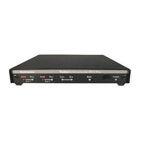
1 and port 2 and (2) instructions for operating each multi-port command. We assume you have installed your station and familiarized yourself with the use of Pacterm with your KPC-9612 Plus, as covered in the chapters on “Installing your KPC-9612 Plus” and “Pacterm.”... - Page 108 Getting Started The Front Panel of the KPC-9612 Plus The following diagram shows the controls and indicators on the front of your KPC-9612 Plus, as well as a brief explanation of each: Kantronics PacketCommunicator 9612 Plus Xmit Xmit Mail Power...
-
Page 109: Beginning A Session
The steps involved in starting a session are covered in the “Pacterm” chapter, so they do not need to be repeated here. Recall that you need to turn on your KPC-9612 Plus and start Pacterm (which runs in your computer and provides you with a way to communicate with the KPC-9612 Plus). -
Page 110: Giving Commands And Transmitting Data
Pacterm (or any other source) as being a command to process, not as data to transmit. To instruct your KPC-9612 Plus to connect, to disconnect, or to change any of the operating parameters in the KPC-9612 Plus you must be in the COMMAND mode. -
Page 111: Trans (Transparent) Mode
Getting Started TRANS (Transparent) Mode A second way to transmit data is to instruct the KPC-9612 Plus to ignore the “control characters” (e.g., “backspace”) and just transmit every character as data. This is called the “TRANS” (transparent) mode of communication. For example, if data received by the KPC-9612 Plus for transmission in TRANS mode includes “backspace”... - Page 112 Switch from giving your TNC commands to using it to send data CONVERS : Switch from COMMAND communication mode to CONVERS (i.e., conversation) Mode. The default way to go back to COMMAND Mode is to enter <Ctrl+C>. : Same as CONVERS. User’s Guide KPC-9612 Plus v 8.2...
-
Page 113: List Of Newuser Commands
MYCALL - Used to set the callsign of your TNC. MYPBBS - Sets the callsign used for your personal mailbox in the TNC. PBBS - Used to set the size (Kbytes) of the Personal BBS in your TNC. KPC-9612 Plus v 8.2 User’s Guide... -
Page 114: Using Newuser Commands
KPC-9612 Plus commands. Check Your KPC-9612 Plus’s Version Number and ID To check your KPC-9612 Plus’s version number and ID all you need to do is ask to see the current setting of the command called VERSION: Step 1. -
Page 115: View Current Values Of Parameters
Type “HELP,” (or “?”) followed by one or more spaces and the name of the command for which you want help. Step 3. The KPC-9612 Plus will send a short “HELP” message about the command, for display on your monitor. View Current Values of Parameters To see the current value of parameter(s) for any variable (other than the “immedi-... -
Page 116: Connect To Your Mailbox
To confirm that the current value(s) is what you want, enter the name of the com- mand and press ENTER, The KPC-9612 Plus will send a message consisting of the name of the command and the current value(s) of it’s parameters for display on your monitor. -
Page 117: Monitor Communications From Nearby Stations
“PBBS (Personal Mailbox) section of the “Modes of Operation” chapter for more details. If you now type the HELP command and press return, you’ll see the KPC-9612 Plus mailbox help file and then the standard mailbox prompt: ENTER COMMAND: B,J,K,L,R,S, or Help> . -
Page 118: Communicate Directly With A Nearby Station
This is normal and may be the result of the settings of the monitoring commands which are dis- cussed in detail in the KPC-9612 Plus Command Refer- ence. As you monitor, you will begin to learn about other packet stations in your area and then you will probably want to try to connect to one of them. - Page 119 Let’s say that you decide to connect to KBØNYK. The steps needed are as fol- lows: Step 1. First, be sure you have the KPC-9612 Plus in command mode. To do this, type <Ctrl+C> and then press return. You should see a command prompt (cmd:).
-
Page 120: Other Topics
1 and/or port 2 (i.e., multi-port commands). Other Topics As you begin working with your KPC-9612 Plus packet radio station, other top- ics that you may wish to explore (with the help of other sections of this manual) include: •... - Page 121 • working with a GPS device. This concludes a quick tour of basic uses of your KPC-9612 Plus. With just these basics, you can do a lot, but you have a great deal more power if you want to ex- plore the full possibilities.
- Page 122 Getting Started Other Topics User’s Guide KPC-9612 Plus v 8.2...
-
Page 123: Modes Of Operation
Modes of Operation This chapter covers the major ways in which you may use your Kantronics TNC. For details on particular commands, see the “Command Reference” chapter. Most Kantronics TNCs are designed with one or two radio ports. The KPC-9612 Plus is unique in that two sets of “railroad”... -
Page 124: Your Packet Unit Is A Terminal Node Controller (Tnc)
Command Mode. This comes defaulted as a <Ctrl+C> (i.e., while holding down the control key, press “C”, then release both keys). Whenever you enter Command Mode the TNC will send a prompt to your screen that looks like this: cmd: User’s Guide KPC-9612 Plus v 8.2... -
Page 125: Connected Vs Unproto
Control key while pressing “C”. You will be going between Command and Convers Modes depending on whether you want to talk to the TNC or have the TNC packetize what you type to go out on the air. KPC-9612 Plus v 8.2 User’s Guide... -
Page 126: A Simple Connect
TNC. Once your station has received the acknowledgment for the disconnect packet the TNC will send this message to your screen: *** DISCONNECTED User’s Guide KPC-9612 Plus v 8.2... -
Page 127: Digipeating
A space must be typed after the “C” and on both sides of the “v”, but digis are separated by commas. A path can also be used with the Unproto command: U CQ V NOM,LCH,SLI,BIX KPC-9612 Plus v 8.2 User’s Guide... -
Page 128: Gateways
The TNC makes it possible for you to talk to more than one person at the same time. Single port TNCs such as the KPC-3 Plus support 26 streams on the one port. Multi-port TNCs (e.g., KPC-9612 Plus) support 26 streams per port. User’s Guide KPC-9612 Plus v 8.2... - Page 129 See example below. For example, let’s assume you are using a KPC-9612 Plus and you are connected to WØXI on stream A of port 2 but you wish to return to a discussion with NØGRG on stream B of port 1.
-
Page 130: Round Table Discussions
(by the AX.25 protocol) be acknowledged end-to-end. Kantronics’ current TNCs (e.g. KPC-3, KPC-3 Plus, KPC-9612, KPC-9612 Plus, among others), use the PERSIST/SLOTTIME algorithm to gain channel access. The default value for DWAIT is set to zero. -
Page 131: Txdelay
FRACK * ((2 * n) + 1) seconds where n is the number of digipeaters. The lower the baud rate (HBAUD) the higher this parameter should be set, because everything is slower. The length of KPC-9612 Plus v 8.2 User’s Guide... -
Page 132: Retries Ax.25 Level 2, Version 1 Vs. Version 2
1, the sending TNC will initiate a disconnect and discard the packet. (The monitoring of the com- mands shown in < > depends on the settings of MRESP, MCON and MCOM.) User’s Guide KPC-9612 Plus v 8.2... -
Page 133: Flow Control
This is called Flow Control and it can be accomplished in either of two ways, via software or via hardware. KPC-9612 Plus v 8.2 User’s Guide... -
Page 134: Software Flow Control
TNC to recognize flow control sent by the computer. If both these commands are ON (and the above commands are set as stated) then software flow control will take place in both directions, to and from the TNC and com- puter. User’s Guide KPC-9612 Plus v 8.2... -
Page 135: Hardware Flow Control
<Ctrl+V> Pass a special character These characters are all very useful when having a packet conversation with someone. If you want to send a packet you hit the return. If you make a mistake KPC-9612 Plus v 8.2 User’s Guide... -
Page 136: Getting Out Of Transparent
If the guard time of one second before and after the three <Ctrl+C>s is not there, the TNC assumes that they are data and sends them to the radio, so be sure to al- low at least one second before and after the three <Ctrl+C>s. User’s Guide KPC-9612 Plus v 8.2... -
Page 137: Remote Access To Your Tnc
52 is “0”, character 22 is “o”, and character 1 is “T”. Therefore, to gain remote access, you must send the following string: sAs0oT Note that case is significant and spaces are considered valid characters. KPC-9612 Plus v 8.2 User’s Guide... - Page 138 To disconnect from a MYREMOTE station, issue a standard disconnect for the station you are operating: press Ctrl+C and Enter to get to the command line (where you will see “Cmd:”), then press D and Enter, to disconnect. User’s Guide KPC-9612 Plus v 8.2...
-
Page 139: Pbbs (Personal Mailbox)
BBS and forward any messages it has. Using Your PBBS In order to use any Kantronics TNC PBBS (even your own), first get the cmd: prompt on your TNC, and then connect to the callsign of the PBBS. For instance, if your MYPBBS is NØKN-1, you would connect to it simply by typing... - Page 140 ENTER COMMAND: B,J,K,L,R,S, or Help > Using anyone else’s Kantronics-based PBBS would result in a similar prompt se- quence. At this point you are ready to send a message to another user, read a message to yourself (if any has been received), or issue any other mailbox command.
-
Page 141: Pbbs Commands
RMINE. Note that the mail-status indicator on the front panel of the TNC is turned ON (without blinking) when someone is connected to your PBBS. PBBS Commands The commands available to users connecting to your Kantronics TNC PBBS (and you connecting directly) are as follows: B(ye) This command is entered by the PBBS user to disconnect from the PBBS. -
Page 142: J(Heard) L(Ong)
BULLETINS addressed to that category. LL n [ ; ] Lists the most recent n number of messages in the mailbox. Again, only BULLE- TINS, TRAFFIC, and PRIVATE which you are allowed to read will be listed. User’s Guide KPC-9612 Plus v 8.2... -
Page 143: Lm(Ine) [ ; ]
BULLETIN or TRAFFIC mes- sages. After you read a PRIVATE message addressed to you, the STATUS flag will automatically be set to Y — it has been read. KPC-9612 Plus v 8.2 User’s Guide... -
Page 144: Rh N
Using this command is the same as using the S(end) command. ST zip The ST (Send Traffic) command is used to send NTS type traffic messages to the PBBS. Some of these commands are described in more detail below. User’s Guide KPC-9612 Plus v 8.2... -
Page 145: Sending Messages
This command sends a private message to WB5BBW. The message should be sent to the W5AC BBS system, in South Texas (.#STX), which is in Texas (.TX), which is in the USA (.USA), which is in North America (.NOAM) where WB5BBW can retrieve it. KPC-9612 Plus v 8.2 User’s Guide... -
Page 146: Listing Messages
09:34:05 Xerox 820 66044 WØOUU 12/19/91 09:33:42 QTC Lawrence 913/842 NØAPJ WØSC 12/19/91 09:33:27 AMTOR NØKN 12/19/91 09:32:49 Need help on AMTOR 9712 BYTES AVAILABLE NEXT MESSAGE NUMBER 7 ENTER COMMAND: B,J,K,L,R,S, or Help User’s Guide KPC-9612 Plus v 8.2... -
Page 147: Reading Messages
Reading Messages To read a message (e.g., a bulletin such as that in the previous section listed as being to ALL), use the READ command (see PBBS comand section for details on using this command). KPC-9612 Plus v 8.2 User’s Guide... -
Page 148: Editing Message Headers
NOT F or from NOT F to F. Similarly, entering H switches the status of the message from H to NOT H or from NOT H to H. Who the message is to or from: >tocall <fromcall The destination mailbox (@BBS): @BBS[.haddr] And the subject or text of the message: User’s Guide KPC-9612 Plus v 8.2... - Page 149 KEYBOARD or as SYSOP over the radio), and issue the com- mand: N >NØGRG You could do this with two separate commands, or it may be accomplished with the single command shown above. KPC-9612 Plus v 8.2 User’s Guide...
-
Page 150: Hierarchical Addresses
If you want to renumber the messages (starting with 1) give the PBBS n command with n being the current size (i.e., nK of memory assigned to the PBBS). User’s Guide KPC-9612 Plus v 8.2... - Page 151 ID (SID) and sign on message. The SID is enclosed in square brackets and con- sists of the unit name, firmware version, and the supported feature set. For example the Kantronics KPC-3 Plus SID is: [KPC3P-7.0-HM$] This is the unit name (KPC3P), version number (7.0) and the feature set (HM$).
-
Page 152: Remote Sysop Access To The Pbbs
(T is the 1st letter, a is the 12th letter, i is the 3rd letter, and so on. See the RTEXT command in the Commands section for a more detailed explanation.) NOTE: Spaces DO count as characters, and case is significant! User’s Guide KPC-9612 Plus v 8.2... -
Page 153: Reverse Forwarding Messages From Your Mailbox
Once a Private or Traffic message has been successfully forwarded out of your mailbox, it will be deleted from the PBBS if PBKILLFW is ON. Bulletins will be marked with a status of “F” and will remain in the PBBS. KPC-9612 Plus v 8.2 User’s Guide... -
Page 154: Selecting A Home Full-Service Bbs
PBBS (Personal Mailbox) Selecting a Home Full-Service BBS. One important use of your Kantronics PBBS is to connect to the national system of packet-radio based BBSs, which was described earlier in the “historical note” at the beginning of the PBBS section. You can use a “home” full service BBS for sending and receiving mail, much as you would use a P.O. - Page 155 By examining this list from the bottom up, we may see that the message entered the system on October 4, 1993 at 15:29 (R:931004/1529). It was message number 46383 on the N5IST BBS (@N5IST) which is located in West Texas (#WTX), KPC-9612 Plus v 8.2 User’s Guide...
- Page 156 (TX). Assuming this BBS is in the United States, it knows TX means Texas and knows that this message needs to be relayed to a station in that area. User’s Guide KPC-9612 Plus v 8.2...
- Page 157 HOME BBS. When you enter a message into your Kantronics PBBS and supply the routing in- formation, that message may be forwarded automatically to another BBS. When the message is forwarded from your Kantronics mailbox, an R: line is included as the originating BBS.
-
Page 158: Paging
TNC and use it to transmit and list logged pages. Hence, you may set up these selected Kantronics TNCs to be the central compo- nent of an amateur paging system. You can then send pages from your computer keyboard and monitor pages with your computer, using any terminal program (e.g.,Pacterm). -
Page 159: Commercial Paging
How does the paging system work as a whole? Let’s investigate by looking at a typical paging system for Anytown, USA as shown in the following diagram. [ PASTE IN — Figure 1-1: add title: Commercial Paging System] KPC-9612 Plus v 8.2 User’s Guide... - Page 160 (or vibrates) the person carrying or wearing it, and stores the message (if a numeric or alphanumeric pager). The person carrying the pager is then free to display the message on the LCD. User’s Guide KPC-9612 Plus v 8.2...
-
Page 161: Amateur Paging
You might wonder at this point how this all fits with amateur radio. Can we retro- fit commercial pagers for amateur use? Can we encode pages? Can we transmit pages? And can we monitor pages? As it turns out, we’re in luck on all four points! KPC-9612 Plus v 8.2 User’s Guide... -
Page 162: Setting Up A Paging System
US 2-meter and 70-cm amateur bands. • Second, selected Kantronics packet modems (TNCs) include POCSAG encoding. A page message is encoded simply by typing in the pager ID and message from a computer keyboard; the TNC does the rest - forming up the page and sending it to the transmitter. -
Page 163: Equipment Requirements
Speaker audio will not work. As you can see, if it weren’t for the development of the 9600 baud packet modem and subsequent availability of data ready radios, amateur paging might not be with us today. KPC-9612 Plus v 8.2 User’s Guide... -
Page 164: Interconnecting The Tnc And Transceiver
Given the low data rates, FSK modulation, wide deviation, and non-scrambling signal format of POCSAG, 1200 baud (AFSK) and 9600 baud ‘RUH’ packet modems are unsuitable (and don’t work) for paging. However, Kantronics’ high speed modems (e.g., KPC-9612 Plus) easily accommo- date POCSAG. Pagers Any of the POCSAG pagers used or sold today may be suitable for amateur use. -
Page 165: Transmitter Drive, Receiver Equalization
While all of these commands are presented in the “Command Reference” section, let’s cover them a bit here since we’re discussing setting up a paging system. KPC-9612 Plus v 8.2 User’s Guide... -
Page 166: Command Setup
For example, if you were callsign WØXI and you transmitted an alphanumeric page to 1234568 with the message CQ CQ CQ DE WØXI K, it would appear as shown below. PAGER>1234568 (3) [04/15/96 10:46:00] CQ CQ CQ DE WØXI K User’s Guide KPC-9612 Plus v 8.2... - Page 167 (3) denotes the function code in the page (e.g., decoding to standard 3 is alpha), and • the date and time shown in brackets are optional (added at the time of reception, if MSTAMP is ON). KPC-9612 Plus v 8.2 User’s Guide...
-
Page 168: Tnc Page Commands
Modes of Operation Paging TNC Page Commands: Paging commands included in Kantronics’ paging TNCs are listed below. Detailed explanations of each are given in the “Command Reference” section. MYPAGE establishes callsign for packet connect to page PAGE initiates a page... -
Page 169: Initiating A (Pocsag) Page
The Page Directory serves the same purpose as a phone book. If you do not know a person’s pager number, you can find it by looking up his name (or call sign) in the Page Directory. KPC-9612 Plus v 8.2 User’s Guide... - Page 170 Access to the page directory by users connecting to the Paging Server (PS) can be partially restricted by asserting the ‘-P’ parameter of the PAGEDIR command when making directory entries and setting up password access. See the page pass- User’s Guide KPC-9612 Plus v 8.2...
-
Page 171: Loging Pages - Pagelog
If a capcode had been specified instead of a nickname, it will appear in the log as the pager address. The * indicates that the page has been entered in the log but not yet sent. KPC-9612 Plus v 8.2 User’s Guide... -
Page 172: Advanced Monitoring Of Pages
N, A, X, or Z, with the following meaning: • N defines c as numeric, • A defines c as alpha, • X defines c as either numeric or alpha, and • Z defines c as “don’t monitor this state assignment". User’s Guide KPC-9612 Plus v 8.2... -
Page 173: Page Server
PAGEMON as: PAGEMON xxxx. Page Server A mailbox-like Page Server (PS) is included in Kantronics paging TNCs. Its pur- pose is to allow packet users to connect to send pages to inquire about the status or content of pages previously sent. -
Page 174: Using The Server
PAGETEXT here (if any) ENTER COMMAND: B, D, L, P, Password, or Help > The first line tells the user that this page server is a KPC-9612 Plus with version 8.2 firmware and that it supports 1200, 2400, 512, numeric and alphanumeric pages, a page directory, group paging, and POCSAG. - Page 175 As before, the ENTER COMMAND instuctions will be displayed at the end of the page log data. To leave the Page Server at this point, simply enter the BYE command (B) and hit return, as follows: This concludes the Paging section of the Modes of Operation. KPC-9612 Plus v 8.2 User’s Guide...
-
Page 176: Gps Nmea Interfacing Capability
GPS NMEA Interfacing Capability GPS NMEA Interfacing Capability Most Kantronics TNCs, e.g. KPC-3 Plus, KPC-9612 Plus, KAM Plus, and others, support the GPS mode, explained below. Each contains firmware to interface with a GPS device supporting the NEMA-0183 interface standard; commands to configure and control unproto (path) retransmissions of the NEMA strings, and provides RAM storage for location messages (strings) for later retrieval. -
Page 177: Gps Equipment Requirements
National Marine Electronics Association (NMEA) 0183 interfacing standard for GPS units and low power. That means your Kantronics TNC is ide- ally suited as a mate for your GPS unit. Over time, a number of software pro- grams will be developed by amateurs to use packet and GPS. -
Page 178: Cabling A Gps Unit To A Kantronics Tnc
0 volts), but use the same polarity as RS-232. These units are capable of driving a Kantronics TNC RS-232 serial data port input pin. However, some GPS vendors in- vert the sense of this signal (true TTL), and these units will not directly interface with a TNC. -
Page 179: Setup: Configuring A Kantronics Tnc For Gps Operation
Also, make sure this pin will accept an RS-232 signal (+ and - voltages). Setup: Configuring a Kantronics TNC for GPS Operation To configure your Kantronics TNC in GPS Mode you must set several command parameters from your PC keyboard as follows: •... -
Page 180: Setting Parameters In The Tnc
If you want LT 1 to beacon with a path of GPS via a digipeater (called DIGI) and you want the beacon to occur every 30 minutes, use the following commands: LTP 1 GPS via DIGI BLT 1 EVERY 00:30:00 User’s Guide KPC-9612 Plus v 8.2... -
Page 181: Gps Unit Initialization From The Tnc
When the TNC resets (either from a RESET command or by turning the TNC off and then on) it will be in the GPS Mode, and the GPSINIT string (if any) will be sent to the serial port. KPC-9612 Plus v 8.2 User’s Guide... -
Page 182: Exiting Gps Mode
In this case, these two users would never beacon at the same time, in fact they would beacon 1 minute apart. Using this system for our example, it is possible to set all thirty users to beacon one minute apart, avoiding collisions. User’s Guide KPC-9612 Plus v 8.2... -
Page 183: Tracking Without Beacons
$PGRMO,GPGSA,1 to the GPS unit, connect to the MYREMOTE of the TNC, verify the password, and send RPRINT $PGRMO,GPGSA,1 to the MYREMOTE. The TNC simply sends this string to its serial port (which is connected to the GPS receiver). KPC-9612 Plus v 8.2 User’s Guide... -
Page 184: Other Notes
This command determines which GPS NMEA sentences will be stored in the LT buffers. GPSINIT string (string up to 128 characters) This command establishes a string that will be sent to the attached GPS unit upon power-up (i.e., initial text sent to terminal in GPS Mode). User’s Guide KPC-9612 Plus v 8.2... - Page 185 LT buffers, and beacons will be transmitted according to the setting of the BLT commands. Hint: To have the TNC exit GPS Mode, connect a PC or terminal to it and issue three <Ctrl+C> characters. KPC-9612 Plus v 8.2 User’s Guide...
-
Page 186: Advanced Gps/Aprs Digipeating
Using generically named digipeaters does result in wider coverage of GPS sta- tions, but several inefficiencies may arise from this common practice (depending upon the availability and names of the digipeaters). User’s Guide KPC-9612 Plus v 8.2... -
Page 187: Overview Of Ui Digipeating Commands
Kantronics’ TNCs (v. 8.2) have a suite of UI digipeating commands that can be used to deal with inefficiencies that can arise when a number of digipeaters are transmitting in the same area, at the same time, using the same generic names. -
Page 188: Using "Ui" Digipeat Commands: Uidigi, Uiflood, And Uitrace
Here, three digis, with MYCALLs of A, B, and C, are configured with aliases of RELAY, WIDE, and TRACE (using UIDIGI); and UIDWAIT is set ON. For ex- ample station A’s UIDIGI aliases are set as follows: cmd: UIDIGI ON RELAY, WIDE, TRACE User’s Guide KPC-9612 Plus v 8.2... - Page 189 (*), then repeats a frame from A and one from C, and, finally, repeats two more (from A,C and C,A) — a total of five! Note that each repeater digis five times so the total number of digipeated packets is 15! KPC-9612 Plus v 8.2 User’s Guide...
- Page 190 The reporting station path is then set to GPS via TRACE4-4, and a UI packet is launched. Any one of the stations monitoring will then display the resulting ac- tion as follows: cmd:NØGRG>GPS,TRACE4-4: <UI>:5 NØGRG>GPS,B*,TRACE4-3: <UI>:5 NØGRG>GPS,A*,TRACE4-3: <UI>:5 NØGRG>GPS,B,A*,TRACE4-2: <UI>:5 NØGRG>GPS,C*,TRACE4-3: <UI>:5 NØGRG>GPS,B,C*,TRACE4-2: <UI>:5 User’s Guide KPC-9612 Plus v 8.2...
-
Page 191: Configuring Digis For Hf/Vhf Gateway Operations
In this example, we demonstrate cross-band (gateway) digipeating, using selected Kantronics TNCs. A UI frame is launched on HF and repeated on VHF four times. A KAM Plus and two KPC-3 Pluses (with call signs C, B, and D) are con- figured as digipeaters and another KAM Plus (call sign A) is set to launch a UI frame from its HF port. - Page 192 “FLOOD4-4" frame because it can’t hear itself! Station B fin- ishes last due to the slot/persist algorithm. D digipeats the frame only once even though it hears both B’s and C’s transmissions since they are within 30 seconds of it’s own transmission. User’s Guide KPC-9612 Plus v 8.2...
-
Page 193: Bibliography
Magellan Systems Corp., 960 Overland Ct., San Dimas, CA 91773. • Sony Electronics Inc., 1 Sony Dr., Park Ridge, NJ 07656. • Trimble - Mobile Computing Products, 645 N. Mary Ave., P.O. Box 3642, Sunnyvale, CA 94088-3642. KPC-9612 Plus v 8.2 User’s Guide... -
Page 194: Ka-Node
KA-Node Overview Most Kantronics TNCs (e.g., KPC-3 Plus, KPC-9612 Plus) include, as a part of their firmware, the Kantronics KA-Node, a packet networking node. If you turn this node on, others may use your station (unattended) not only as a digipeater but as a node, enabling them to find pathways to other stations and making those pathways more efficient. -
Page 195: Configuring Your Ka-Node
Packets passing through your KA-Node are monitored unless your MYNODE callsign is included in the SUPLIST, if turned ON. If it becomes necessary to dis- connect a station from your KA-Node, you can issue the command DISCON- KPC-9612 Plus v 8.2 User’s Guide... -
Page 196: Using A Ka-Node
Personal Mailbox. Some Kantronics TNCs, such as the 9612 Plus, are multi-port. These multi-port KA-Nodes can support cross-connects, Xconnects; that is, users may connect on one port and then connect out another port, which may be attached to another radio set to a different frequency. - Page 197 At this point you are “patched” through the KA-Node LAW to the node KC. When LAW issued the connect request to KC it used your own call but sub- tracted a count of one from your SSID. For example, if you connected to LAW KPC-9612 Plus v 8.2 User’s Guide...
- Page 198 KC and LAW handles its own error checking. In this way, one weak link will not cause end-to-end packets and acknowledgments to be repeated as they would with digipeating. The result is substantial improvement in throughput for connections using nodes. User’s Guide KPC-9612 Plus v 8.2...
- Page 199 B(ye) to the BBS, you would remain connected to the KA-Node closest to the BBS. If you issue the connect without the STAY option, any disconnect from ei- ther end will cause the entire link to disconnect. KPC-9612 Plus v 8.2 User’s Guide...
-
Page 200: Automatic Disconnect
Using the XCONNECT Command Note: The XCONNECT command is available only on Kantronics’ multi-port TNCs, such as the KPC-9612 Plus. Single-port TNCs (e.g., KPC-3 Plus) do not support this command, but they may connect to a KA-NODE that does. The cross-connect (XCONNECT) command is a unique feature of the KA-Node. -
Page 201: Determining Which Port You Have Connected To
[ ] are optional and if used the UPPER/LOWER case convention applies. ABORT Aborts a KA-Node Connect or Xconnect request if it is the first data sent after the connect request. It must be spelled out entirely. Causes the KA-Node to initiate a disconnect. KPC-9612 Plus v 8.2 User’s Guide... -
Page 202: Connect Callsign [Stay]
01/10/88 00:03:10 NØKN-3/H 01/10/88 00:03:19 NØGRG/V 01/10/88 00:04:15 (VHF/UHF Multi-Port) LAWKAN/1* 01/09/88 08:25:15 N66046/2 01/10/88 00:03:10 NØKN-3/1 01/10/88 00:03:19 NØGRG/2 01/10/88 00:04:15 (Single-Port) LAWKAN 01/09/88 08:25:15 N66046* 01/10/88 00:03:10 NØKN-3 01/10/88 00:03:19 NØGRG 01/10/88 00:04:15 User’s Guide KPC-9612 Plus v 8.2... -
Page 203: Nodes [Short|Long]
Causes the node to issue a connect request to “callsign” (in the usual AX.25 for- mat) on the opposite port of the KA-Node. Cross-connecting enables you to gain access, via the node, to another frequency. KPC-9612 Plus v 8.2 User’s Guide... -
Page 204: Other Modes Of Operation
Pacterm and Procomm Plus. Remote Sensing and Control You can use two (or more) packet radio stations, each containing a Kantronics TNC, to implement remote sensing and/or remote control, as follows: •... - Page 205 Reference. You can also use the ANALOG and/or CTRL commands, without the REMOTE command, to carry out sensing and control functions at a local Kantronics TNC. The following diagram illustrates the use of two Kantronics TNC/radio stations for remote control and sensing. These operations could be carried out manually or via a terminal program running in the computer in the central TNC station.
-
Page 206: Modem Mode
Using your TNC in MODEM mode, with a PC and communications software, you can copy these broadcasts. The content of the broadcasts may be plain ASCII text (copyable with Pacterm - shipped with Kantronics TNCs) or graphics (copyable with “WeatherNode” software, carried by Kantronics). Interpretation User’s Guide... -
Page 207: Kantronics Host Mode Operation
FEND character (ASCII code 192), then the letter q (upper or lower case is ok), and finally another FEND character. Your TNC will then leave Host Mode, switch to COMMAND mode, and send the usual Kantronics sign-on message. If you use a terminal program other than Pacterm, it may send these characters au- tomatically, or it may require that you carry out this same procedure to get out of HOST mode and to COMMAND mode. - Page 208 TCP/IP command (available in KISS software while in KISS mode), or • send the C0 FF C0 sequence from your keyboard. To send the C0 FF C0 sequence from your keyboard (using a PC compatible computer): User’s Guide KPC-9612 Plus v 8.2...
-
Page 209: Xkiss (Extended Kiss) Mode
TNCs on the same serial port, to provide multiple radio ports to the node. Otherwise, XKISS works like KISS. For information on this mode of operation, see the documentation for the XKISS software you are using. KPC-9612 Plus v 8.2 User’s Guide... -
Page 210: Dama (Slave Mode) Capacity
DAMA (Slave Mode) Capacity All of Kantronics’ current amateur TNCs (KAM Plus, KPC-3 Plus, and KPC-9612 Plus) support the DAMA protocol (slave mode) as used by many ama- teur radio operators in Germany, Belgium, Luxembourg, the Netherlands, France, Switzerland and other parts of Europe. -
Page 211: How Is Dama Implemented In Kantronics Tncs
(see the Command Reference section for details): DAMA {ON|OFF} Set DAMA to ON to have your Kantronics TNC operate as a DAMA slave sta- tion once a connection is established with a DAMA master station. When DAMA is OFF, the TNC will operate in it’s carrier sense multiple access mode (CSMA). -
Page 212: Bibliography
Relay League, Newington, CT, USA 06111. Published in German as “DAMA, ein neues Verfahren für Packet Radio?” cq-DL April 1989. TheNetNode (TNN) Copyright 1994, NORD><LINK e.V., c/o Klaus-Dieter Vieth, Goergesstrasse 3, D-38118 Braunschweig, Germany. NET/ROM is a trademark of Software 2000, Inc. User’s Guide KPC-9612 Plus v 8.2... - Page 213 Modes of Operation CAUTION! The DAMA firmware in Kantronics’ TNC is based on documentation published in the ARRL Computer Networking Conference papers (see Bibliography) and documentation provided by NORD><LINK, the developers of DAMA. This firmware was tested with TheNetNode firm- ware (Version 1.56), TFKISS (Version 2.0) and by volunteer testers in Europe with firmware used...
-
Page 215: Command Reference
KPC-family TNC. Information spe- cific to a particular model is included as needed. The 9612 Plus is a multi-port device. Every KPC-9612 Plus has two ports: port 1 is a low-speed port and port 2 is a high-speed port. This command reference docu- ments which commands may use port 2 as well as port 1 and how port 2 may be used. -
Page 216: Format For Listing Commands
— and selects the first match with the string you enter. The command name is followed by a space. After the space, there may be one or more parameters that need to be used, or that may optionally be used, with the command. User’s Guide KPC-9612 Plus v 8.2... - Page 217 For multi-port commands, default pa- rameter values for each port are shown, with port 1 value listed first, followed by a slash “/” and then port 2 value. KPC-9612 Plus v 8.2 User’s Guide...
- Page 218 Number codes for these special characters are shown in hexadecimal (hex) form (i.e., base 16). They can be entered either in decimal or in hex. Permissible val- ues are shown in HEX: for example (n = $00 - $FF). User’s Guide KPC-9612 Plus v 8.2...
- Page 219 A callsign may additionally include an “extension” (SSID, Secondary Station Identifier), which is a decimal number from 0 to 15 used to KPC-9612 Plus v 8.2 User’s Guide...
- Page 220 When you are at the Command Mode prompt, you enter a command for the TNC by typing the command name (in upper or lower case) and any required and op- tional parameter values (argument settings or values). User’s Guide KPC-9612 Plus v 8.2...
- Page 221 Hint: You can examine the value of any parameter by typing the command name followed by a “CR”. A special command, DISPLAY, allows you to see the values of all parameters or groups of related parameters. KPC-9612 Plus v 8.2 User’s Guide...
- Page 222 ABAUD setting and reinitialize the TNC to perform the autobaud routine. (See Hard Reset section.) Note also that a hard reset will erase ALL stored parameters in your TNC and return them to factory defaults. See also: reset, restore User’s Guide KPC-9612 Plus v 8.2...
- Page 223 ANALOG immediate The KPC-9612 Plus has the capability of reporting the status of two lines of ana- log data from sensors or switches that may be wired to radio port 2. The proces- sor in the 9612 Plus contains an A/D converter and this A/D converter, in combination with added circuitry, can convert the two analog voltages presented at port 2 into 8-bit binary equivalent values.
- Page 224 2 packets. You may also find benefit from setting this command OFF when using several digipeaters (not nodes) to send packets, or when conditions are marginal between User’s Guide KPC-9612 Plus v 8.2...
- Page 225 Repeaters using slow mechanical relays, split-sites, or both require some amount of time to get RF on the air. See also: axhang AXHANG (n = 0 - 255) Multi-Port default 0/0 KPC-9612 Plus v 8.2 User’s Guide...
- Page 226 When ON, the sequence backspace-space-backspace is sent to the attached termi- nal when the DELETE character is entered. When OFF, the backslash character “\” is sent to the terminal when the DELETE character is entered. User’s Guide KPC-9612 Plus v 8.2...
- Page 227 The transmitted bandwidth is slightly wider than a G3RUH modem. When ON, the transmitted bandwidth is slightly narrower than the G3RUH modem, and the transmitted eye pattern is slightly dis- torted, but will work with most radios. KPC-9612 Plus v 8.2 User’s Guide...
- Page 228 TNC responds with “EH?” and returns you to the command prompt). Similarly, you can remove a single callsign (-callsign) from the list. And to re- move all items from the current list, enter BUDLIST NONE. User’s Guide KPC-9612 Plus v 8.2...
- Page 229 CANLINE (n = $00 - $FF) default $18 <Ctrl+X> This command is used to change the cancel-line input editing command charac- ter. When in Convers or Command Mode entering a <Ctrl+X> will cancel all KPC-9612 Plus v 8.2 User’s Guide...
- Page 230 — using an energy type carrier detect — allowing shared voice and data on the same channel. For each port, set to EXTERNAL, the carrier detect is supplied by an external de- vice, connected to the XCD pin on that radio port. User’s Guide KPC-9612 Plus v 8.2...
- Page 231 TRIES), a standard disconnect sequence will be initiated. If n equals 0, this “timeout” function is disabled. When using Version 1 (AX25L2V2), a check timeout will initiate a disconnect right away. See also: ax25l2v2, kntimer, relink, rnrtime, tries KPC-9612 Plus v 8.2 User’s Guide...
- Page 232 Your TNC can send a custom connected text message (stored in CTEXT) to a station making a connection request to your station. The CMSG command is used to control whether this message is sent and, if so, what the TNC will do af- ter sending the message. User’s Guide KPC-9612 Plus v 8.2...
- Page 233 The CONLIST command can be used to add a single callsign (+callsign), so long as there is room for the new callsign on the list (if there is not, the TNC responds with “EH?” and returns you to the command KPC-9612 Plus v 8.2 User’s Guide...
- Page 234 Each callsign may also have an optional Secondary Station Identifier (SSID) specified as -n, where n = 1 - 15. The digipeat callsigns are specified in the order in which they are to relay transmitted packets. The mode set by CONMODE will User’s Guide KPC-9612 Plus v 8.2...
- Page 235 <DM> packet will be sent to the requesting station. The message “connect re- quest: (callsign of whoever is trying to connect to you)” will be output to your terminal if INTFACE is TERMINAL or NEWUSER. When CONOK is OFF, you can still connect to your mailbox. KPC-9612 Plus v 8.2 User’s Guide...
- Page 236 CPACTIME {ON | OFF} default OFF When OFF and in the Convers Mode, packets are sent when the SENDPAC char- acter is entered or when PACLEN is achieved. When ON and in the Convers User’s Guide KPC-9612 Plus v 8.2...
- Page 237 {ON | OFF} default OFF This command was added to the first multi-mode TNCs (such as the Kantronics UTU and KAM) to accommodate the practice by radio teletype (RTTY) opera- tors of adding an extra carriage return (CR) at the end of each line (i.e., CR, CR, linefeed (LF) ).
- Page 238 Or, to pulse the B output of port 2 three times, you’d issue the command CTRL B /3. If you do not specify A or B both lines are affected, and if you do not specify a port (by using the “/” character) lines in both ports are affected. User’s Guide KPC-9612 Plus v 8.2...
- Page 239 DAMA master station. When OFF the TNC operates in standard Packet mode (i.e., CSMA — Carrier Sense Multiple Access). For details, see the section on DAMA in the Modes of Operation chapter. KPC-9612 Plus v 8.2 User’s Guide...
- Page 240 10. Entering two characters will force a two digit display for values under 10. If the month is entered as three ms, it will be displayed as the first three characters of the month name (JUL). User’s Guide KPC-9612 Plus v 8.2...
- Page 241 January 2, at 22:30:00 hours, the value of the DAYTIME parameter would be 860102223000. In this case, seconds were entered, so the string is 12 characters long (2 characters for each of six pieces of information entered). KPC-9612 Plus v 8.2 User’s Guide...
- Page 242 (D) command. By issuing two Disconnects instead of one with your Disconnect (D) command, your station will not wait for the distant station to acknowledge a Disconnect (D) command (i.e., the first one sent) before disconnecting. See also: disconnect User’s Guide KPC-9612 Plus v 8.2...
- Page 243 Entering a second Disconnect command before RETRY has expired will result in an immediate disconnect on your end, but may leave the other station thinking it is still connected to you. Dis- KPC-9612 Plus v 8.2 User’s Guide...
- Page 244 (TNC to computer) CHAR special TNC characters parameters related to GPS operations ID parameters LINK parameters affecting packet link (TNC to TNC) MONITOR monitor parameters PBBS mailbox commands PAGE page commands TIMING timing parameters User’s Guide KPC-9612 Plus v 8.2...
- Page 245 Persistence and Slottime to determine proper transmit in- tervals, and setting DWAIT to 0. See also: persist, slottime ECHO {ON | OFF} default ON KPC-9612 Plus v 8.2 User’s Guide...
- Page 246 Normally, equalization is set/adjusted while receiving packets from another sta- tion or, preferable, a calibration signal from another station. If the other station has a Kantronics KPC-9612 or KPC-9612 Plus, they can send you a scrambled 9600 baud calibration signal, using the CAL command, so that you may set equalization with this or the calibrate command (CAL).
- Page 247 When FLOW is ON, any character entered from the terminal will halt output to the terminal until the current packet or command is completed (by SENDPAC, PACLEN, or PACTIME). Canceling the current input to the TNC or typing the REDISPLAY-line character will also cause output to resume. KPC-9612 Plus v 8.2 User’s Guide...
- Page 248 See also: connect, retry FULLDUP {ON | OFF | LOOPBACK} Multi-Port default OFF/OFF FULLDUP is used to set the TNC for half-duplex or full-duplex operation. User’s Guide KPC-9612 Plus v 8.2...
- Page 249 GPS units may require more than one sentence; consult your GPS unit manual. To send more than one, enter a <Ctrl+N> at the end of each sentence, and the TNC will send a CR/LF sequence to the GPS unit. A single % will clear the string. KPC-9612 Plus v 8.2 User’s Guide...
- Page 250 When receiving packets addressed only to you (MONITOR and/or MCON OFF) this parameter does not apply. When OFF the data will be on the same line as the header. User’s Guide KPC-9612 Plus v 8.2...
- Page 251 Do not enter your callsign or the first period of your packet address. A hierarchical address consists of your state, country, and continent codes, sepa- rated by periods. For instance, a station in Rhode Island might use a hierarchical KPC-9612 Plus v 8.2 User’s Guide...
- Page 252 “/B” and MYPAGE addended with /P. This packet will be addressed to “ID” and digipeated via any addresses specified in the UNPROTO command. See also: hid, unproto INTFACE {TERMINAL|NEWUSER|BBS|KISS|XKISS| HOST|GPS|MODEM} default NEWUSER User’s Guide KPC-9612 Plus v 8.2...
- Page 253 G8BPQ extended KISS protocol (for more information, see the KISS Operation section of this manual). When INTFACE is set to HOST, the TNC will talk to the attached computer using the Kantronics HOST mode and users com- municate with the TNC using “host mode” software (for more information, see the HOST Operation section of this manual).
- Page 254 When ON, no character translation occurs in the TNC. If OFF, lower case charac- ters will be translated to upper case before being output to the terminal from the TNC. This case translation is disabled in Packet Transparent Mode. User’s Guide KPC-9612 Plus v 8.2...
- Page 255 LLIST command can be used to add a single callsign (+callsign), so long as there is room for the new callsign on the list (if there is not, the TNC responds with “EH?” and returns you to the command prompt). Similarly, you can remove a KPC-9612 Plus v 8.2 User’s Guide...
- Page 256 GPS; however, you may want to change it to APRS, LOCATE, POSIT, or some other destination. Check on conventions used by your local GPS community. Up to 8 digipeater callsigns may be specified. See also: lt User’s Guide KPC-9612 Plus v 8.2...
- Page 257 Setting MALL OFF is useful when stations are talking as a group in an uncon- nected configuration, thus eliminating display of “connected” conversations heard on the receive frequency. See also: monitor MAXFRAME (n = 1 - 7) Multi-Port default 4/4 KPC-9612 Plus v 8.2 User’s Guide...
- Page 258 This option is included for those providing BBS service via both ports, while only being able to accept one connect at a time. See also: status, streamsw, users MBEACON {ON | OFF} Multi-Port default ON/ON User’s Guide KPC-9612 Plus v 8.2...
- Page 259 <Is> Information frame (connected); s = send sequence number See also: ax25l2v2, monitor, mresp For details on control packets, see the book AX.25 Amateur Packet-Radio Link-Layer Protocol Version 2.0 October 1984, available from the ARRL. KPC-9612 Plus v 8.2 User’s Guide...
- Page 260 [SHORT | LONG | CLEAR] immediate This command causes display of a list of stations heard. An asterisk, *, indicates that the station was heard through a digipeater. The date/time the station was last heard is also displayed. User’s Guide KPC-9612 Plus v 8.2...
- Page 261 The addresses in each packet are displayed along with the data portion. Callsigns (to and from fields) are separated by a “>”; and the Secondary Station Identifier (SSID) is displayed if it is other than 0. If any data is contained in the monitored KPC-9612 Plus v 8.2 User’s Guide...
- Page 262 = send sequence number, r = received sequence number See also: ax25l2v2, mcom, monitor For more information, see the book AX.25 Amateur Packet-Radio Link-Layer Protocol Version 2.0 October 1984, which may be obtained from the ARRL. User’s Guide KPC-9612 Plus v 8.2...
- Page 263 When ON, the TNC will monitor (i.e., output to your computer screen) transmit- ted packets. Repeated packets will be displayed as they are sent over the radio. The frames to be displayed will be controlled by the MONITOR, MCOM, KPC-9612 Plus v 8.2 User’s Guide...
- Page 264 - since it has none. The callsign you enter then is automatically used for MYCALL and to compute other IDs (MYPBBS, MYNODE, and CWIDTEXT), adding an SSID for each. Changing MYCALL at the “cmd:” prompt does not affect MYPBBS, MYNODE, or CWIDTEXT. User’s Guide KPC-9612 Plus v 8.2...
- Page 265 (n = 0-15) Multi-Port default 0/1 This command sets the KISS address of the radio ports in the KPC-9612 Plus. A KISS frame with the upper nibble of the command byte set to this value will ad- dress this TNC.
- Page 266 MYCALL, MYALIAS, MYNODE, or MYPBBS. In addition, the RTEXT must be programmed with a text string to enable remote access. For de- tails, see the Remote Access section of the Modes of Operation chapter. See also: rtext; remote access section User’s Guide KPC-9612 Plus v 8.2...
- Page 267 TNC. The list includes KA-Nodes as well as K-Net, TheNet, NET/ROM and G8BPQ nodes. These nodes are identified as: ALIAS (CALLSIGN) and Kantronics KA-Nodes will be identified as: MYNODE (MYCALL) An asterisk"*" indicates that the station was heard through a digipeater. The date/time the station was last heard is also displayed.
- Page 268 (when a remote station connects to a KA-Node). Enter any combination of characters and spaces up to a maximum length of 128. Entering a single “%” will clear NTEXT. See also: mynode, numnodes User’s Guide KPC-9612 Plus v 8.2...
- Page 269 (if FULLDUP is OFF). This can be used to op- erate two modems (e.g., 1200 and 9600) on one frequency. When OFF, each port of the TNC detects presence of a signal independent of the other port. See also: cd KPC-9612 Plus v 8.2 User’s Guide...
- Page 270 If format and rate are not specified, a numeric message is sent to name or capcode at 1200 bits per second (BPS). Up to 20 numbers are accepted for numeric pagers. User’s Guide KPC-9612 Plus v 8.2...
- Page 271 If n is set to 0, no CWID is sent. The message contained in CWIDTEXT will be sent as the ID at 15 wpm using a 1200 hertz tone. Action specified by the CWID command still applies. See also: cwid, cwidtext KPC-9612 Plus v 8.2 User’s Guide...
- Page 272 The format of the pagelog list is shown in the Paging section of the Modes of Op- eration. PAGEMON {ON|OFF|cccc} (each c must equal N, A, X, or Z) default OFF. User’s Guide KPC-9612 Plus v 8.2...
- Page 273 ‘DC’ content of the paging message is severely degraded by most au- dio circuits. See also: mon, mstamp, headerln PAGEPRIV {ON | OFF} default OFF This command restricts the page server to password access only when ON. See also: pagepswd KPC-9612 Plus v 8.2 User’s Guide...
- Page 274 RPC1 calls for all pages to be sent with the same “sense,” However, not everyone follows that standard. If the page signal is to be inverted, set PAGEXINV to ON. The setting of the command has no affect on page monitoring. When monitoring, User’s Guide KPC-9612 Plus v 8.2...
- Page 275 100 (if RAM = 128K), or 480 (if RAM = 512K) Setting n greater than 0 allocates memory and activates the Personal Mailbox in the TNC. The amount of memory allocated will be n kilobytes, and may be lim- KPC-9612 Plus v 8.2 User’s Guide...
- Page 276 PBREVERS is ON. Note that full-service BBS systems must be configured to al- low your station to reverse forward mail to you. Note: Your PBBS will not forward or reverse forward unless HTEXT is set. See also: pbrevers,htext User’s Guide KPC-9612 Plus v 8.2...
- Page 277 PBBS after they have been forwarded, but will be marked with an F flag (for- warded). When ON, Private and Traffic messages will be deleted from the PBBS after they have been successfully forwarded. KPC-9612 Plus v 8.2 User’s Guide...
- Page 278 When PBLIST is ON, the callsigns on the current PBLIST list are included as “mine” for use with the “mail” indicator and the PBBS commands (LISTMINE, READMINE, and KILLMINE). Your callsign (MYCALL) and your MYPBBS are also included as “mine” when PBLIST is ON. User’s Guide KPC-9612 Plus v 8.2...
- Page 279 When ON, only messages addressed to the MYCALL , MYPBBS or PBLIST callsigns will be accepted over the radio, but a message entered from the terminal or by the SYSOP may be addressed to anyone. See also: mycall, mypbbs, pbbs KPC-9612 Plus v 8.2 User’s Guide...
- Page 280 256.) If the TNC generated random number is greater than PERSIST, the TNC restarts the timer and waits for the timer to expire again before generating a new random number. This is repeated until the TNC gains channel access and sends its packet of information. User’s Guide KPC-9612 Plus v 8.2...
- Page 281 If you wish to monitor with PID ON, you also may want to set the FILTER pa- rameter ON. This will prevent monitored data that may look like control charac- ters from being sent to your terminal. KPC-9612 Plus v 8.2 User’s Guide...
- Page 282 Enter any combination of characters and spaces up to a maximum length of 128. Entering a single “%” will clear PTEXT. Don’t use the “>” character in your PTEXT, as this is reserved by BBS systems for their prompt. See also: pbbs User’s Guide KPC-9612 Plus v 8.2...
- Page 283 OFF/OFF When OFF, the TNC operating with AX25L2V2 ON does not attempt to auto- matically reconnect. When ON, the TNC operating with AX25L2V2 ON will at- tempt to automatically reconnect after RETRY is exceeded. KPC-9612 Plus v 8.2 User’s Guide...
- Page 284 This command specifies the number of packet retries. Packets are re-transmitted n times before an operation is aborted (due to no response). The time between re- tries (when no acknowledgment is received) is specified by the command FRACK. User’s Guide KPC-9612 Plus v 8.2...
- Page 285 GPS unit, or to change configuration or set- tings in a Repeater controller (not available when the TNC INTFACE is set to HOST, KISS or MODEM mode). KPC-9612 Plus v 8.2 User’s Guide...
- Page 286 You will be given a maximum of three attempts to properly de- code the password string. If you fail in three attempts, the TNC will disconnect. After failing in three attempts, the MYREMOTE is disabled for 15 minutes. User’s Guide KPC-9612 Plus v 8.2...
- Page 287 (n = 0 - 255) Multi-Port default 10/10 n specifies the amount of time, in 10 millisecond increments, between successive tries of the persistence algorithm. See also: persist START (n = $00 - $FF) default $11 <Ctrl+Q> KPC-9612 Plus v 8.2 User’s Guide...
- Page 288 (see CONPERM). cmd:status long FREE BYTES 1661 stream - #50(2) CONNECTED to KEØSM stream - IO CONNECTED to NØKN/P stream - DISCONNECTED stream - DISCONNECTED stream - DISCONNECTED stream - DISCONNECTED User’s Guide KPC-9612 Plus v 8.2...
- Page 289 (controlled by STREAMEV). This is especially useful when operating with multiple connec- tions allowed. See also: mcon, monitor, streamev STREAMEV {ON | OFF} default OFF KPC-9612 Plus v 8.2 User’s Guide...
- Page 290 A through Z, or a through z, limited by the value of MAXUSERS. If more than one port is active in the KPC-9612 Plus and you wish to change to a stream on another port, you need to insert the port number between the streamswitch character and the stream designator.
- Page 291 ”callsign1<>callsign2" will block display of packets from callsign1 to callsign2 and vice versa. Note that an entry of callsign1>callsign2 or callsign1<>callsign2 counts as 2 of the 10 allowed callsigns. See also: monitor KPC-9612 Plus v 8.2 User’s Guide...
- Page 292 Mode. The current link state is not affected. There are no special editing charac- ters, all characters are sent out as received. To get out of Transparent, send the TNC a modem break if BREAK is ON, or see CMDTIME for a special keyboard sequence. User’s Guide KPC-9612 Plus v 8.2...
- Page 293 8, “TRIES 3” would reset the counter to make the TNC believe that it had only tried 3 times so far, thus allowing 7 more attempts before the RETRY limit is exceeded. See also: retry KPC-9612 Plus v 8.2 User’s Guide...
- Page 294 Mode (including the XON and XOFF characters) by setting TXFLOW ON, XFLOW ON and TRFLOW OFF. You will not, however, be able to receive the START and STOP characters, since your terminal program should interpret them as flow control. See also: trans, trflow, xflow User’s Guide KPC-9612 Plus v 8.2...
- Page 295 APRS applications. See also: dwait, persist, uidwait UIFLOOD name, n,[ID|NOID] (name = 5 char max)(n=0-255) Multi- Port default disabled,30,NOID/disabled,0,NOID KPC-9612 Plus v 8.2 User’s Guide...
- Page 296 MYCALL with the H bit set is inserted before the to-be-digipeated field, the ssid of the to-be-digipeated field is decremented, and the UI frame is digipeated without setting the H bit of the to-be-digipeated field. User’s Guide KPC-9612 Plus v 8.2...
- Page 297 For example, if USERS = 5 then an incoming connect request will connect to the lowest channel A - E, if any of these channels are in the unconnected state. If none of the 5 channels are available (all of them are KPC-9612 Plus v 8.2 User’s Guide...
- Page 298 $00, software flow control is not possi- ble. In the Transparent Mode flow control is also determined by the settings of TRFLOW and TXFLOW. See also: start, stop, trflow, txflow, xoff, xon User’s Guide KPC-9612 Plus v 8.2...
- Page 299 0 to 255) from 2 - 100 mV p-p if jumper J20 is Off and from 80 mV to 4 V p-p if J20 is ON (i.e. jumper on both pins, which is the factory default placement). Most high-speed radios prefer the high (default) drive. KPC-9612 Plus v 8.2 User’s Guide...
- Page 300 If set to $00 hardware flow control must be used. For software flow control set this parameter to the character the computer expects to see to restart sending data to the TNC. See also: xflow, xoff User’s Guide KPC-9612 Plus v 8.2...
- Page 301 Command Reference KPC-9612 Plus v 8.2 User’s Guide...
- Page 303 TTL levels (such as the Commodore 64), you will need an after-market converter to supply the RS-232 signals required by the KPC-9612 Plus. Caution: Make sure the power to the transceiver, computer, and KPC-9612 Plus is OFF before connecting any cables.
- Page 304 All Kantronics software requires five wires between the computer and the KPC-9612 Plus. The pins that must be connected from your KPC-9612 Plus to the computer for these programs are Txd, Rxd, SG, RTS, and CTS. If you are us- ing other software, you should refer to that documentation to determine the cable requirements for proper operation.
- Page 305 Applying Power through the DB-25 connector. If desired, you may apply DC power to the KPC-9612 Plus from Pin 25 (EXT-IN) of the DB-25 connector. To enable this, connect J2 center pin and Pin 1, J3 center pin and Pin 2.
- Page 306 Plus, you must set the serial port configuration in your program for 8 data bits, no parity, and one stop bit. The baud rates supported by the KPC-9612 Plus are 300, 600, 1200, 2400, 4800, 9600, 19200 and 38400. In general you should use the fastest baud rate your terminal program and hardware supports.
- Page 307 Pin 1: Connects to the microphone input of your radio, providing the audio sig- nal to be transmitted. Pin 2: When a ground is applied to this pin, the KPC-9612 Plus will not transmit packets. This pin is normally used as an external means of supplying carrier detect, but can also be used as a “hardware”...
- Page 308 Pin 6: This pin connects to the ground of your radio mic connector. Pin 7: This pin is not normally connected in the KPC-9612 Plus, but may be con- figured as an external reset or to supply power to the KPC-9612 Plus using jump- ers J2 and J3.
- Page 309 To accomplish this, simply install a resistor (approximately 3.9K seems to be a good value) in series with the PTT wire from the KPC-9612 Plus, and connect this to the mic input along with the AFSK line.
- Page 310 Applying Power through the DB-9 connector. To power the KPC-9612 Plus from Pin 7 of the DB-9 connector, you must con- nect J2 center pin and pin 2, J3 center pin and pin 2. Resetting the KPC-9612 Plus through the DB-9 connector.
- Page 311 Pin 9: This pin connects to the ground of your 9600 baud radio. Pin 10: This pin is connected to ground (same as pin 9). Pin 11: This pin is connected to ground (same as pin 9). KPC-9612 Plus v 8.2 User’s Guide...
- Page 312 Note: If your radio requires a lower drive level, place the jumper on just one pin of J20 and readjust the digital drive Pot, using XMITLVL or CAL commands to set drive from 2mV p-p to 200 mV p-p. User’s Guide KPC-9612 Plus v 8.2...
- Page 313 To reassemble, reverse the above procedure. Hard Reset The hard reset process is provided to re-initialize the KPC-9612 Plus to its de- fault values. This process may become necessary should operational problems be encountered or when upgrading your firmware to a new version. The readout specified in step 5 below will be legible only if your terminal baud rate is 9600.
- Page 314 Appendix B: Advanced Information Calibration/Equalization 1. Turn OFF power to the KPC-9612 Plus and remove the top cover, as de- scribed above. 2. Locate the Hard Reset jumper (J12). Jumpers are appropriately labeled on the PC board. Refer to the parts location diagram for help in locating them.
- Page 315 AFSK drive level by press- ing the ‘-’ or ‘+’ key (and holding it down) until you achieve the drive level you need. Adjust deviation to achieve about 3 to 3.5 kHz deviation from your radio. KPC-9612 Plus v 8.2 User’s Guide...
- Page 316 Receive Equalization. If you have another Kantronics user nearby, have that station transmit a calibrate square wave and choose the R option in your calibrate mode to measure the sta- tus of port 1 receive equalization. You will see two numbers displayed each time you press R.
- Page 317 30 seconds on the high speed (e.g., 9600 baud) port, the watchdog timer will activate and release the PTT line to your radio. To disable the Watchdog timer, connect the pins of J19, or J8, together. KPC-9612 Plus v 8.2 User’s Guide...
- Page 318 A/D Converter Two A/D converter inputs are available to the KPC-9612 Plus and are used with the Analog command. These inputs can be used to measure “DC” external volt- ages from 0V to 5VDC, with up to 8-bit accuracy.
- Page 319 Chip enable (clock) RAM +5V Power Supply KPC-9612 Plus Jumper Descriptions: J1: (DB-9 Ground or reset) This three-pin jumper connects pin 9 of the 1200 baud radio port to ground or to the reset function. When placed on the center post and 1, pin 9 of the DB-9 connector is connected to ground.
- Page 320 HC11 processor. Default: Connected. J10: (Analog input AN0) Same setup as J9. J11: (port 3 20-pin header) For future use to connect a baby board to the 9612 Plus (main) printed circuit board (pcb). User’s Guide KPC-9612 Plus v 8.2...
- Page 321 RAMs in the 9612 Plus. When placed on the center post and pin 1, the 9612 Plus can accept up to/including a 128K static RAM. When placed on the center post and 2, the unit accepts a 512K static RAM. Default center post and 1. KPC-9612 Plus v 8.2 User’s Guide...
- Page 322 (not connected). NOTE: the Dallas DS1215 real-time clock chip in the KPC-9612 Plus is not rated for +3.3 volt operation, so for low voltage operation, the clock chip must be removed and pins at J22 and J23 connected (i.e., J22 and J23 ON).
- Page 323 Appendix C: Options for the KPC-9612 Plus Low Power Operation Your KPC-9612 Plus is capable of very low power operation. In order to achieve the lowest power consumption possible, you must turn the front panel LEDs off with the command LEDS OFF. Also, the modem must be set for INTERNAL carrier detection with the command CD INTERNAL.
- Page 324 Installing Additional RAM Installing Additional RAM The KPC-9612 Plus is shipped with 128K bytes of RAM. It is possible to ex- pand the RAM in the KPC-9612 Plus up to a maximum of 512K bytes. Expanding the RAM to 512K bytes requires that you: •...
- Page 325 Additional possible difficulties are covered in the “Trouble-Shooting” section of the “Pacterm” chapter. Your Kantronics KPC-9612 Plus is manufactured to very stringent quality stan- dards. If you have followed the installation procedures outlined in this manual, it is highly unlikely that you will encounter a failure. If you do have difficulty, use the procedures described in this section to assist in isolating and correcting the problem.
- Page 326 (See the XMITLVL parameter in the command reference for de- tails). 5. Check to be sure the KPC-9612 Plus is set to transmit on the proper port. Check the I/O port by entering the STATUS command. If needed, change ports by using the streamswitch character.
- Page 327 PASSing the dollar sign. Symptoms for this usually are that you can talk to the KPC-9612 Plus fine in Command Mode, you can usually talk to others on the air, but you just can’t get back to Command Mode. With most PC terminal programs, pressing <Ctrl+C>...
- Page 328 KEYPAD (do not use the numbers above the letters on the keyboard). Then release the ALT key. When your terminal program sends these characters, the TNC will switch you out of Host Mode and into Command Mode. User’s Guide KPC-9612 Plus v 8.2...
- Page 329 Specifications Appendix E: Additional Information Appendix E: Additional Information Specifications paste-in specs for 9612 Plus KPC-9612 Plus v 8.2 User’s Guide...
- Page 330 Messages from the KPC-9612 Plus The following are brief explanations of the most important messages that may be sent by your TNC. Note: Since these messages are also sent by other Kantronics’ TNCs, they refer to “TNC”, not to “KPC-9612 Plus”. ***(callsign) busy The packet station you were attempting to connect to (callsign) is unable to accept connects, and responded with a busy signal.
- Page 331 CHECKSUM ERROR This message indicates that the Kantronics firmware in your TNC may be damaged. You may see this message when performing a hard reset, or any time a soft reset is performed (including initial power up), and an EPROM error is detected.
- Page 332 Appendix E: Additional Information Messages from the KPC-9612 Plus *** connect request: A remote packet station has attempted to connect to you, but there is not a valid stream available for the connection. The remote station will be sent a busy message, packet.
- Page 333 Messages from the KPC-9612 Plus Appendix E: Additional Information ***FRMR received: A frame reject packet has been received for an unknown reason. The infor- mation field of this packet will display in hexadecimal value. This display may be useful in determining why the receiving station rejected your packet.
- Page 334 Appendix E: Additional Information Messages from the KPC-9612 Plus Link state is: This message is output in response to the CONNECT and DISCONNECT commands if the state of the link does not permit the requested action. It is prefaced by “Can’t CONNECT” or “Can’t DISCONNECT” as appropriate and will be followed by the current link state.
- Page 335 Messages from the KPC-9612 Plus Appendix E: Additional Information Waiting ACK and device busy Your TNC has sent a packet to another station and is waiting for the ac- knowledgment, but your TNC is not able to accept any data from the radio at this time.
- Page 336 Appendix E: Additional Information Messages from the KPC-9612 Plus PBBS MESSAGE BUFFER NOT VALID! TRYING TO RECOVER When you turn on the TNC a check is made of the pointers relating to the PBBS. It appears that one or more of these pointers may not be correct. An attempt is made to correct them, but it is possible that some or all of the mes- sages may be lost.
- Page 337 Messages from the KPC-9612 Plus Appendix E: Additional Information Whenever one of the parameters is changed, the previous value is usually displayed. Example: cmd:AX25 OFF AX25L2V2 was ON KPC-9612 Plus v 8.2 User’s Guide...
- Page 338 Appendix E: Additional Information ASCII Chart ASCII Chart [paste in page 1 of 2 ASCII chart] User’s Guide KPC-9612 Plus v 8.2...
- Page 339 ASCII Chart Appendix E: Additional Information ASCII CHART, continued [paste in page 1 of 2 ASCII chart] KPC-9612 Plus v 8.2 User’s Guide...
- Page 340 Appendix E: Additional Information KPC-9612 Plus Parts List KPC-9612 Plus Parts List (copy/paste-in — page 1 of PARTS list (from p.123))] User’s Guide KPC-9612 Plus v 8.2...
- Page 341 KPC-9612 Plus Parts List Appendix E: Additional Information (copy/paste-in — page 2 of PARTS list (from p.124))] KPC-9612 Plus v 8.2 User’s Guide...
- Page 342 Appendix E: Additional Information KPC-9612 Plus Parts Layout KPC-9612 Plus Parts Layout paste-in LAYOUT DIAGRAM [see p 213 of earlier edition] User’s Guide KPC-9612 Plus v 8.2...
- Page 343 TNC with Pacterm, 71 TNC, receive, 72 connect, 110, 216 TNC, temporary, 79 CONNECT command, 19 TNC, transmit, 87 connect request, 217 connect to radio, 287-292 connected packet, 23 Connected vs. Unproto, 109 KPC-9612 Plus v 8.2 User’s Guide...
- Page 344 163 DISPLAY, 226 setup with TNC, 162 DWAIT, 114, 227 slotted beacons, 165 supported by TNC, 159 GPS, 159 ECHO, 227 GPS device End-of-File code, 83 connecting, 61 entering commands, 202 GPS/APRS digipeating, 169 User’s Guide KPC-9612 Plus v 8.2...
- Page 345 179 interfacing, 288 using XCONNECT, 183 hard reset, 293 KAM, 86 hardware flow control Kantronics Program and Info. disk, 67 CTS, 78 KISS Mode, 190 RTS, 78 KISS protocol, 26 Help, 98, 232 HF Non-Packet modes of operation, 86...
- Page 346 154 PBBS Commands, 125 page monitor, 254 persistence, 114 page monitoring Personal Mailbox (PBBS), 123 advanced, 155 POCSAG, 145 page server, 156 POCSAG paging, 142 pager ports, 112 capcode, 155 position reporting stations, 169 User’s Guide KPC-9612 Plus v 8.2...
- Page 347 8BITCONV, 72 installing, 42 CANLINE, 71 RS-232C cable, 68 CANPAC, 71 RTS, 78 COMMAND, 71 RTTY, HF non-packet mode, 86 ECHO, 72 run Pacterm from floppy drive, 67 FILTER, 72 FLOW, 72 MONITOR, 72 KPC-9612 Plus v 8.2 User’s Guide...
- Page 348 UNPROTO packet, 23 unproto UI packets, 169 Unproto vs. Connected, 109 upgrade note, 12 VERSION, 279 very low power, 303 watchdog timer microprocessor, 298 PTT, 297 weather broadcasts copying, 189 XKISS Mode, 192 XKISS protocol, 26 User’s Guide KPC-9612 Plus v 8.2...
Need help?
Do you have a question about the KPC-9612 Plus and is the answer not in the manual?
Questions and answers