Table of Contents
Advertisement
Quick Links
Advertisement
Table of Contents

Related Manuals for Kantronics KAM XL


Summary of Contents for Kantronics KAM XL
- Page 1 KANTRONICS KAM XL Reference Manual...
-
Page 2: Table Of Contents
Front panel of the KAM XL ............................... 18 Rear panel of the KAM XL ..............................18 CONNECTING THE KAM XL TO A POWER SOURCE ....................19 CONNECTING THE KAM XL TO A COMPUTER ......................19 The Terminal Program ..............................23 CONNECTING THE KAM XL TO TRANSCEIVERS.................... - Page 3 Networking terms ................................52 K-Net SYSOP Commands ..............................53 K-Net USER commands: ..............................57 GPS NMEA, Weather station Interfacing ..........................60 Overview ................................... 60 GPS Equipment Requirements ............................60 Cabling a GPS Unit to the KAM-XL ..........................61 Configuring the GPS Commands ............................61 Other GPS Features ................................
- Page 4 Calibration ..................................187 PTT (Push-to-Talk) Watchdog Timer ..........................189 Jumpers.................................... 190 Appendix C: Replacing the Lithium Battery ........................192 Appendix D: In Case of Difficulty ............................193 Appendix E: Additional Information ........................... 195 Messages from the KAM XL ............................195...
-
Page 5: Contact Us
Contact Us: Kantronics 14830 W. 117 Olathe, Kansas 66062 Orders/Inquiries (913) 839-1470 FAX (913) 839-8231 E-mail sales@kantronics.com Website: www.kantronics.com Service/Technical Support (913) 839-8143 (8 AM to 12PM and 1 to 5 PM Central Time, M-F) FAX (913) 839-8231 E-mail service@kantronics.com... -
Page 6: Revisions
The Kam XL is manufactured in the U.S.A. © Copyright 2000-2015 by Kantronics. All Rights Reserved. Contents of this publication or the firmware within the Kam XL may not be reproduced in any form without the written permission of the copyright owner. -
Page 7: Kantronics Warranty Registration
Please take the time to (print this page) fill out the warranty registration form and mail it to Kantronics, including a copy of your sales receipt, to register your purchase. Refer to the warranty policy in this manual for further information. -
Page 8: Important
SOFTWARE and accompanying written materials on a permanent basis provided you retain no copies and the recipient agrees to the terms of this Agreement. Kantronics may terminate this Agreement without notice if you violate any terms or conditions of the Agreement. In the event of termination of the Agreement, provisions relating to Kantronics’... -
Page 9: Limited Warranty
To receive notice of future updates, new product information and prompt warranty service, please fill in the Kantronics Warranty Registration form COMPLETELY and return it along with a copy of proof of purchase (to establish purchase date) by any means to us (see our Contact Us page).Warranty Registration form and proof of... - Page 10 Kantronics; or to any product damaged or impaired by shipping (whether or not caused by poor packaging), neglect, accident, wiring not installed by Kantronics, improper parameter settings which are cleared by performing a hard reset, or use in violation of instructions furnished by Kantronics or of generally accepted industry practice.
-
Page 11: Return/Repair Procedures
It may be useful to perform a “Hard Reset”. (See Hard Reset section.) If service or repairs still appear necessary after you have checked the items listed above, it may be wise to call, fax, e-mail or write Kantronics to determine if the problem can be solved without returning the unit. - Page 12 To be eligible for repair under warranty, we must have a record that you sent your Warranty Registration and proof of purchase to Kantronics, and the item(s) must still be within the warranty period at the time the return is authorized.
-
Page 13: Radio Frequency Interference Statement
Radio Frequency Interference Statement Note 1: This equipment has been tested and found to comply with the limits for a Class B digital device, pursuant to Part 15 of the FCC Rules. These limits are designed to provide reasonable protection against harmful interference in a residential installation. This equipment generates, uses and can radiate radio frequency energy and, if not installed and used in accordance with the instructions, may cause harmful interference to radio communications. -
Page 14: Fcc Declaration Of Conformity
Ground leads should be as short as possible and go to an EARTH GROUND FCC Declaration of Conformity: NOTE: This equipment, Kantronics’ KAM XL, has been tested and found to comply with the essential emission and immunity requirements of the EMC Directive FCC Title 47, Part 15, Subpart B. The test results are on file at the corporate offices of Kantronics. -
Page 15: Introduction
2 radio port connectors. The KAM XL advances the state of the art beyond the pioneering Kantronics' KAM, KAM Plus, and KAM XL products in a number of ways, including increased processing power, larger amount of RAM, more available operating modes, and DSP modems. -
Page 16: E-Mail
Kantronics TNCs). Configurations: The KAM XL is easy and flexible to configure to operate in selected modes, with a wide range of external devices, including remote TNCs, GPS devices, weather stations, external modems, and remote sensing and control devices. Configuration is done by command entry from a terminal program, external port selection, and internal jumper settings. -
Page 17: Installation
This chapter covers the hardware side of setting up a packet radio station. The KAM XL is a multi-port device. Radio Port 1 is for low speed packet and HF non-packet modes, and Port 2 is a packet port, with each port connected to different transceivers. Unless otherwise noted, the steps involved for installing the two radio-to-transceiver connections are the same. -
Page 18: Additional Parts Required For A Multi-Mode Radio Station
Additional Parts Required for a Multi-Mode Radio Station In addition to the KAM XL unit, the following parts are needed to set up a multi-mode digital communications radio station: HF and/or VHF transceivers, with microphone (Mic) jack and external speaker or accessory jack connectors ... -
Page 19: Connecting The Kam Xl To A Power Source
Exceeding the maximum input voltage or applying power with reversed polarity, can cause problems operating the KAM XL or may cause damage to the unit or the power supply. When using a fused power lead, do not use a fuse larger than 500 mA. - Page 20 9 or 25 pins. A FEMALE connector is needed on the computer-end of the serial cable, to connect to the computer's serial port. To use the KAM XL with a non-PC type of computer, use a serial communication program and a serial modem cable normally used to connect a “HAYES” type high-speed telephone modem, to that computer.
- Page 21 FG - FRAME GROUND: This pin is attached to the chassis of the equipment as a safety ground TXD - TRANSMIT DATA: This line carries data output from the computer, to the KAM XL RXD - RECEIVE DATA: This line carries data input to the computer, from the KAM XL...
- Page 22 DSR - DATA SET READY: This line is set high by the KAM XL to indicate that it is powered DCD - DATA CARRIER DETECT: the KAM XL to signal the status of the current I/O stream to the computer uses this line.
-
Page 23: The Terminal Program
If the computer did not come with an RS232 serial port installed, one must be added to be able connect to the KAM XL. There are many makers of accessory serial port adapter devices to plug into a USB jack. When acquiring one of these adapters, make sure it is designed to work with the operating system in your computer, with drivers from the operating system supplier, or with drivers from the device maker. -
Page 24: Connecting The Kam Xl To Transceivers
Connectors for the radio end of the cable are not included with the KAM XL.You will need to get the proper connector to match the jack on the radio, to which you will connect the completed cable from the KAM XL. - Page 25 A shielded cable must be used with the shield properly terminated 360 to the connector. See the instructions for making the cable assembly under Port 1. Detailed descriptions of the radio ports on the KAM XL are located in the appendix sections.
-
Page 26: Aux Port (Rs232 - Dte)
AUX PORT (RS232 – DTE) The AUX port is an RS232 serial port, for connection from the KAM XL to other devices. It is configured as a DTE port, the same as a computers serial port. -
Page 27: Interface Communication Modes Of The Kam Xl
Exiting Host mode If a Host mode program has been used to operate the KAM XL, it may leave the KAM in Host mode when it exits. If a standard terminal program is then used (set to the same interface baud rate) to communicate with the KAM XL, instead of a “sign-on”... -
Page 28: Kiss Mode
To place the KAM XL in KISS Mode, at the command prompt (cmd:), type INTFACE KISS and press return. Then, send a RESET command, or cycle power (off/on) to the KAM. The KAM XL will remain in KISS interface mode, until it receives the KISS exit code, or it has been hard reset. -
Page 29: Xkiss (Extended Kiss) Mode
38-42, 6th Computer Networking Conference, Newington, CT: ARRL, 1987. XKISS (Extended KISS) Mode The KAM XL also supports the G8BPQ multi-drop KISS Mode, called extended KISS (XKISS). With this mode, the TNC can be connected to a G8BPQ node along with other TNCs on the same serial port, to provide multiple radio ports to the node. -
Page 30: Communication Modes In The Kam Xl
COMMUNICATION MODES IN THE KAM XL The KAM XL is a multi-mode controller and/or Terminal Node Controller (TNC) Packet Mode Packet radio modems, or packet modems, are generally referred to as TNCs. This "label" or "moniker" was adopted when the Tucson Area Packet Radio Group (TAPR) developed their first "TNC-1" packet radio modem kit in the early 1980s. - Page 31 When transmitting UNPROTO packets, the UNPROTO command sets the destination or “to” address of those packets. Its default setting is CQ. Enter the Convers Mode to send a CQ message, by entering the command CONV<CR> or K<CR>. Then, typed and entered characters will be packetized and transmitted as data, and not be interpreted as commands.
- Page 32 TNCs can digitally-repeat or “digipeat” packets, to help other stations reach a destination station that they can not hear direct. In Kantronics TNCs, the command that controls this function is called DIGIPEAT and its default setting is ON. In many areas, a dedicated “DIGI”, consisting of a properly configured TNC, a radio and antenna, are installed in a high location to provide digipeater capabilities for many local stations.
- Page 33 Gateway, are heard on one port of that TNC, and are re-transmitted out from the TNCs other port. Multi-Connects The KAM XL allows packet “connect” links (or streams) to as many as 26 other stations, on each of its radio ports, at the same time.
- Page 34 (by the AX.25 protocol) be acknowledged end-to-end. The use of the PERSIST/SLOTTIME algorithm to gain channel access is standard in Kantronics’ TNCs. The default value for DWAIT is set to zero. If the DWAIT method is used, the TNC sending non-digipeat packets will wait for DWAIT (times 10 ms) time of clear channel before beginning to key-up the radio to transmit.
- Page 35 been sent) and is suspended when data carrier from the radio is present, or when your station is transmitting. Retries in AX.25 Level 2, Version 1 vs. Version 2 The way retries are accomplished depends on AX25L2V2 being OFF or ON. If a packet is transmitted to a connected station, and an acknowledgement is not received back, the entire packet is retransmitted (with the same frame number) up to the number of tries specified by the RETRIES command, until an acknowledgement is received.
-
Page 36: Remote Access
RTEXT is a password character string. In a local TNC, command it to connect to the MYREMOTE callsign in the remote KAM XL. It will respond to the connect request, with three lines of six numbers per line. Pick one of the lines, and enter the characters at the positions indicated in the line, as entered in RTEXT. -
Page 37: Other Packet Modes Of Operation
Using the PBBS In order to use any Kantronics TNC PBBS (even your own), first get the cmd: prompt, and then connect to the callsign of the PBBS. For instance, if the MYPBBS is set to use the callsign NØKN-1, connect to it by typing "CONNECT NØKN-1". - Page 38 (i.e. HM$). The supported features in the PBBS of the KAM XL are Hierarchical forwarding, Message ID, and BID. These identifiers are the SID definitions published by Hank Oredson (WØRLI) with his Community BBS system.
-
Page 39: Pbbs Commands
When the PBBS is connected to any station, the Mail LED on the front panel will be lighted. When the PBBS is not connected, and contains unread messages addressed to the MYCALL, MYPBBS, or any of the callsigns or names entered in the PBLIST command, the Mail LED will blink. The PBLIST is also used with the PBPERSON command and the following PBBS commands: LMINE, KMINE, and RMINE. - Page 40 LC [cat [;]] The LC command by itself, will cause the PBBS to list only the TO field of all BULLETINS in the mailbox. If a category is specified (i.e. LC RACES) the PBBS will list the full message headers of all BULLETINS addressed TO that category. LLn [;] Lists the most recent n number of messages in the mailbox that the current user is allowed to read.
- Page 41 SP call The SP (Send Private) command is used to send a PRIVATE message to a specified callsign. Using this command is the same as using the S(end) command. ST zip The ST (Send Traffic) command is used to send NTS type traffic messages to the PBBS. Some of these commands are described in more detail below.
- Page 42 Listing Messages When listing messages with any of the LIST commands, a display will be similar to the one shown below. If the optional semi-colon (;) is specified in the list command, the display will also include the @BBS field (if it exists) in square braces after each line. MSG# ST SIZE TO FROM...
- Page 43 This command, available only to users with SYSOP access, allows the editing of headers and content of any message in the mailbox. Sysop access is automatic when connecting from a local terminal, or can be granted to remote users connecting to the PBBS over the radio, by password control. See the section titled "Remote Sysop Access to the PBBS"...
- Page 44 Reverse Forwarding Messages from the Mailbox The TNC mailbox will allow entry of messages to be forwarded to a full-service BBS (RLI, MBL, etc). These messages have a special format, and can be entered in any personal mailbox. Entering an @ BBS in the address of a message, will make that message available to be forwarded or reverse forwarded to a full service BBS.
-
Page 45: Advanced Pbbs Configuration
Most of the TNC functions remain active, even when the terminal is turned off or disconnected from the KAM XL. When this is the case, other stations connecting to the MYCALL of the KAM XL can be sent to the mailbox automatically, to leave a message or read messages addressed to them. -
Page 46: Remote Sysop Access To The Pbbs
Remote SYSOP Access to the PBBS Users of the PBBS through a radio connection can gain remote SYSOP access by entering the SYSOP command as the first command after connecting to the PBBS. Upon receiving the SYSOP command from a remote user, the PBBS will return three lines of five numbers each. -
Page 47: Ka-Node
NET/ROM, X1J, or Kantronics K-Net. Consequently, users cannot issue a connect to a distant station without knowing the path - as they sometimes can with a fully featured node. -
Page 48: Using A Ka-Node
The X command, for cross-connect, is a unique feature of the KA-Node. It allows cross-linking between two frequencies through the node in much the same manner as the Kantronics unique gateway, but with local acknowledgment of packets.When a connecting station wishes to connect to a station that can be reached through the other port of the TNC, he sends the X {callsign} command. -
Page 49: Remote Commands Of The Ka-Node
The X command, for cross-connect, is a unique feature of the KA-Node. It allows cross-linking between two frequencies through the node in much the same manner as the Kantronics unique gateway, but with local acknowledgment of packets. - Page 50 The long (JHEARD L) version of this command will include date/time stamp, the destination field, and any digipeaters used. Nodes [Short|Long] Causes the node to return a list of KA-Nodes it has heard, as well as K-Net, G8BPQ, NET/ROM and TheNet nodes.
-
Page 51: K-Net
G8BPQ evolved. Although these variants differ in their features, they all utilize the same basic networking protocol. The K-Net feature adds the function of a dual-port network node to the operation of the KAM XL. All normal functions of the KAM XL can remain active, including PBBS operation, dual-port (packet) operations, and remote access. -
Page 52: Networking Terms
ETLINKS, NETROUTE, and NETUSERS) will also cause a soft reset, as memory is allocated for their use. Their functions and parameter value ranges are listed in the command section. Other K-Net node parameters can only be accessed or changed, while connected to the node as sysop. Unlike the KA-Node, which can not be accessed from the local terminal, a K-Net node will accept a connect request from the local terminal, allowing sysop access to change the network node parameter settings. -
Page 53: K-Net Sysop Commands
These system operator (SYSOP) commands are available to the user at the keyboard attached to the KAM XL, when connected to its network node callsign. The same commands can be accessed from another packet station, after gaining sysop access (by entering the SYSOP command, and entering the correct password characters, as set in the RTEXT command). - Page 54 for whatever reason, and then returns, it will automatically be assigned the locked quality. During the time that this neighbor is absent, it, and distant nodes associated with this neighbor, may eventually be removed from the nodes table (even if the route is locked) because the obsolescence count for this neighbor node could drop to zero.
- Page 55 Sets the interval, in number of minutes, of the node ID beacon from each port of the node. This is not a nodes broadcast, just an ID. Setting either or both numbers to 0 (zero), turns off the ID beacon. (n = 0 –...
- Page 56 Sets the time, in number of seconds, that the originating node will wait before resending a level 4 data packet if no acknowledgment is received from the destination node (end-to-end info- ACK). If set to small, multiple copies of the same packet can exist within the node system, even if the first packet was received correctly.
-
Page 57: K-Net User Commands
1, and the third number is for port 2. K-Net USER commands: These commands are available to any user connecting to the network node callsign in the KAM XL, from another packet station. - Page 58 The AX.25 STATEs are: 1 for DISCONNECTED, 2 for CONNECT IN PROGRESS, 3 for FRMR CONDITION DETECTED, 4 for DISCONNECT ATTEMPT IN PROGRESS, 5 for CONNECTED, 6 for WAITING ACKNOWLEDGEMENT, 7 for DEVICE BUSY, 8 for REMOTE DEVICE BUSY, 9 for BOTH DEVICES BUSY, 10 for WAITING ACKNOWLEDGEMENT and DEVICE BUSY, 11 for WAITING ACKNOWLEDGEMENT and REMOTE DEVICE BUSY, and 12 for WAITING ACKNOWLEDGEMENT and BOTH DEVICES BUSY.
- Page 59 NOTE: NBAUD and GPSPORT cannot be enabled at the same time. The AUX port of the KAM XL can be used for only one function at a time. Attempts to enable both functions at the same time will...
-
Page 60: Gps Nmea, Weather Station Interfacing
GPS NMEA, Weather station Interfacing The KAM XL can be interfaced with a GPS device that provides data in the NEMA-0183 interface standard, to weather stations that have a compatible data output. It has a complete set of commands to configure and control unproto (path) retransmissions of the NEMA strings, and can provide RAM storage for location messages (strings) for later retrieval. -
Page 61: Cabling A Gps Unit To The Kam-Xl
TNC by incorrect connections to other devices, or connection to incompatible devices. To connect the data port of a GPS unit to the KAM XL, a cable with at least two wires is required. A shielded cable is preferred. Refer to the GPS manual to determine which pins are used for signal ground, and data output. -
Page 62: Other Gps Features
(so that old non-updated data is not transmitted more than once), include the optional parameter CLEAR after the time interval. If both ports of the KAM XL have been enabled, and are currently in Packet mode, the LT buffers can be beaconed from either one or both radio ports (and at different intervals, if desired). - Page 63 BLT 1 EVERY 00:30:00 START 00:01:01 In this case, these two users beacons would never be transmitter at the same time, but would beacon 1 min apart. Using this system as an example, it would be possible to set all thirty users to beacon 1 min apart, avoiding collisions.
-
Page 64: Gps Command Summary
Other text can be specified in the GPSHEAD command. If the data input to the AUX port is in the same format as NMEA data, that begins with a specific character or word and ends in a CR/LF (carriage return/linefeed) sequence, it can be stored in the LT buffers. Some weather station devices operate in this manner to report weather information. -
Page 65: Advanced Gps/Aprs Digipeating
Kantronics' TNCs have a suite of UI digipeating commands that can be used to deal with inefficiencies that can arise when a number of digipeaters using the same generic names are located in the same area, and can transmit at the same time. -
Page 66: Configuring Digis For Hf/Vhf Gateway Operations
MYALIAS.) Configuring Digis for HF/VHF Gateway Operations The commands MYGATE and UIGATE are used to configure the KAM XL as a cross-port digi for UI packets. MYGATE sets the callsign of the cross-port digi, and UIGATE enables or disables the direction of the gateway. - Page 67 General Information Bruninga, Bob, WB4APR, "Automatic packet reporting system (APRS)", 13th ARRL Digital Communications Conference Proceedings, 1994. (available from: ARRL, 225 Main Street, Newington, CT, 06111) Sproul, Keith, WU2Z, "MacAPRS", 13th ARRL Digital Communications Conference Proceedings, 1994. Technical Information Collins, J., et al., GPS Theory and Practice, Second Edition, Springer-Verlag, 1993. Etherington, Michael, "FM subcarrier network extends differential GPS nationwide", Mobile Radio Technology, February 1994.
-
Page 68: Other Functions
OTHER FUNCTIONS Some of the following modes of operation require special software, so they may not be available when using standard terminal programs such as Pacterm or Procomm Plus. TELEMETRY Analog Inputs The eight analog inputs are available in the TELEMETRY connector. These inputs can be used to measure external "dc"... -
Page 69: Dama
TNCs, which contain firmware (EPROM) that can operate in a DAMA "slave" mode (such as the Kantronics TNCs with DAMA slave mode support). The slaves may use a standard terminal or host mode program or any of a variety of specially written European programs, such as SP, Grafik Packet and ESKAY, some of which make use of the KISS mode feature of the TNC. - Page 70 This would increase the probability of collisions with other users, thus defeating the purpose of the DAMA system. The following commands enable and configure DAMA mode in the KAM XL: DAMA, and DAMACHCK Set DAMA to ON to operate as a DAMA slave station, once a connection is established with a DAMA master station.
-
Page 71: Hf Modes (Non-Packet)
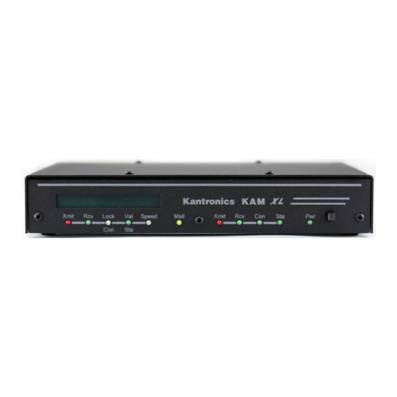
The BARGRAPH display on the front panel of the KAM XL is a tuning aid to properly adjust the receiver frequency to decode signals. The right end of the BARGRAPH is MARK, and the left end is SPACE. -
Page 72: Transmitting Cw
Transmitting CW To transmit CW, the KEY OUT pin (pin 4) from the HF radio port of the KAM XL must be wired to the CW key jack on the transceiver. An FET switching transistor applies a connection to ground on this pin when sending CW. -
Page 73: Cw Directives
CW character is received. If the CWOUTPUT command does not include the PTT option, the Transmit LED on the front panel of the KAM XL will not light when transmitting in CW, and the PTT line will not be activated. CW Directives While in CW mode, several command functions are active, and cause these actions as indicated: <Ctrl+C>E Return to receive mode when transmit buffer is empty... -
Page 74: Rtty
To transmit RTTY, type <Ctrl+C>T. This causes the KAM XL to key your transmitter, the bargraph in the KAM XL goes dark, and the transmit LED light. Type the message you wish to send and when you are through, type <Ctrl+C>E. The KAM XL will transmit your message and, when the data has been transmitted, return to the receive mode. -
Page 75: Mars Feature
<Ctrl+C>L Send LETTERS shift character <Ctrl+C>N Send FIGURES shift character <Ctrl+C>R Return to receive mode immediately. (If the transmit buffer isn’t empty, remaining data will stay in the buffer.) <Ctrl+C>T Enter transmit mode <Ctrl+C>X Exit RTTY, discard any data in the transmit buffer, and return to Command mode. <Ctrl+C>n Change operating speed. - Page 76 To display exactly what is received from the other station, set CRSUP OFF and LFSUP OFF so that the KAM XL does not suppress any of the received carriage return or line feed characters.
-
Page 77: Ascii
When tuning in an ASCII signal, adjust the receivers operating frequency so that the tuning bargraph on the KAM XL lights brightest at both ends. If the received signal is ASCII, but is displayed as garbled characters, the signal may be inverted (space/mark, instead of mark/space). If this is the case, send the directive <Ctrl+C>I to invert the demodulator in the KAM XL, or set the receiver to the... - Page 78 <Ctrl+C>E Return to receive mode when transmit buffer is empty. <Ctrl+C>I Invert received MARK/SPACE signals and invert transmitted MARK/SPACE if using AFSK (SSB) <Ctrl+C>R Return to receive mode immediately. (If the transmit buffer isn’t empty, the remaining data will stay in the buffer.) <Ctrl+C>T Enter transmit mode <Ctrl+C>X Exit ASCII, discard any data in the transmit buffer, and return to Command mode.
-
Page 79: Amtor (Includes Lamtor, Fec, Selfec, Navtex)
SELCAL can be changed at any time, with the MYSELCAL command. In addition, the KAM XL supports a 7-character SELCAL and generates a unique SELCAL for this mode from its callsign. The KAM XL will accept a link from another station with either the 4- character or 7-character SELCAL. -
Page 80: Answering A Cq
When the KAM XL receives and displays the +?, it becomes the ISS, and can now send data to the other station. When you want the other station to again send data to you, type the +? on your keyboard. -
Page 81: Mode B (Fec) Operation
To receive only addressed FEC messages, set the AUTOSTRT command ON, then enter the AMTOR Standby mode or the FEC mode as described above. The KAM XL will now copy only Mode B SELFEC transmissions that begin with the specified SELCAL. -
Page 82: Notes On Amtor Operation
If, while monitoring Mode A signals, received characters seem to be garbled, the <Ctrl+C>R directive will force the KAM XL to attempt to re-synchronize to the signal. NOTE: The LAMTOR mode is receive only, and transmit can not be enabled. -
Page 83: Navtex
NAVTEX NAVTEX/AMTEX Theory Navtex transmissions are, in reality, Mode B AMTOR (FEC). What makes Navtex unique, however, is the actual message format. Navtex stations always transmit on 518 kHz LSB, and are generally located on the coastlines. The American Radio Relay League (ARRL) is now using the same format on a daily basis to transmit bulletins. -
Page 84: Navtex/Amtex Operation
F Pilot messages G Decca message H LORAN-C message I Omega message J Differential Omega message Z QRU - no message on hand K-Y Reserved NOTE: K has been proposed for “other electronic navigational aid system message.” Once a message has been received from a particular station with less than a specified amount of errors, it will not be printed again, as the receiving system keeps track of the message numbers it has received. -
Page 85: Navtex Directives
NAVMSG selects which message classes to display (only those selected, or ALL). NAVERR specifies the percent of errors allowed in a received message before considering the message as not being received properly, and discarding it. If message classes A, B, or D are left out of the list of valid message classes to be received, a WARNING message will be displayed, since the NAVTEX specification requires that these classes must be printed at least once. -
Page 86: Pactor (Ptl, Ptfec)
Next, enter the PACTOR command and include the callsign of the station heard transmitting the CQ message. The KAM XL will start transmitting a link request to the other station. If the other station has properly acknowledged the link request, message “ LINKED TO xxxxxx” will be displayed. Since... -
Page 87: Ptlisten Mode
you initiated the link, you are the Information Sending Station (ISS) and may begin entering a message. When finished, and ready to receive from the other station, type <Ctrl+C>E. A change-over request will be sent to the other station, allowing them to become the ISS station, so that messages they send can be received and displayed. -
Page 88: G-Tor (And Gmon)
MYGTCALL callsign. If you now tune your KAM XL to a station transmitting AMTOR FEC, you’ll be able to copy that transmission. You’ll also be ready to receive a link request in G-TOR mode from another station. -
Page 89: Tuning G-Tor
Next, enter the GTOR command and include the callsign of the station heard transmitting the CQ message. The KAM XL will start transmitting a link request to the other station. If the other station has properly acknowledged the link request, message “ LINKED TO xxxxxx” will be displayed. Since you initiated the link, you are the Information Sending Station (ISS) and may begin entering a message. -
Page 90: Pbbs Access In G-Tor
Hints for G-TOR Operation When choosing to use the FSK mode of a transceiver, the FSK output from the KAM XL must be connected to the FSK input of the transmitter. The actual tones transmitted are controlled by radio in this mode, and the MARK and SPACE commands in the KAM XL must be set to match the tones received. -
Page 91: Summary Of Gtor Directives
The KAM XL will automatically exit data transparency if the other station breaks the link, or anytime the linked state is exited (due to errors or too many retries). - Page 92 <Ctrl+C>2 Force 200 baud operation (IRS only) <Ctrl+C>3 Force 300 baud operation (IRS only) <Ctrl+C><Ctrl+T> Toggle TRACE mode ON/OFF MODEM BREAK Exit data transparency mode...
-
Page 93: Psk31
Upon entering PSK31 mode, the mode indication is displayed: <125-2000-3875> The KAM XL is now in receive mode can decode a properly tuned PSK31 signal, and will display monitored information on the terminal. The default modulation type is PSK. To switch to QPSK, enter the <Ctrl+C>Q directive. To return to PSK modulation, enter <Ctrl+C>P. - Page 94 <Ctrl+C>R Return to receive mode immediately. (If the transmit buffer isn’t empty, remaining data will stay in the buffer.) If sent while still in receive mode, will cause a re-sync to the signal currently in the center of the tuning BARGRAPH. <Ctrl+C>T Enter transmit mode <Ctrl+C>1, <Ctrl+C>2, <Ctrl+C>3, <Ctrl+C>4, <Ctrl+C>5, <Ctrl+C>7, <Ctrl+C>8, <Ctrl+C>9, <Ctrl+C>0;...
-
Page 95: Command Reference
RAM and will be the value used at future power-on. The availability of the commands listed here depends upon what INTFACE (i.e., INTERFACE) mode the KAM XL is currently in (see the INTFACE command in the command listing below and check the index for more information on INTFACE modes). - Page 96 Values that need to be entered as they are shown (or by using the short-form indicated by the underlined character(s)) are shown in CAPS, as in “ON | OFF”. Parameter names for which a value needs to be substituted are shown in lower case letters, as in “callsign,” which means a particular callsign needs to be entered.
- Page 97 Amateur call (such as a base station and a repeater). The callsign and extension are entered and displayed as call-ext, e.g. NØGRG-3. If the extension is not entered, it is set to -0, and extensions of -0 are not displayed by the KAM XL.
-
Page 98: Entering Commands
<Ctrl+C>s in rapid succession to switch to the Command Mode and get the “cmd:” prompt. When you are at the Command Mode prompt, you enter a command for the KAM XL by typing the command name (in upper or lower case) and any required and optional parameter values (argument settings or values). -
Page 99: Commands
This is done either by sending a RESET command, or powering the unit OFF and back ON. To make a change of the communication baud rate between the terminal and the KAM XL, change the ABAUD setting first, then change the baud rate setting in the terminal program in the computer. - Page 100 Entering the AMTOR command alone enters the AMTOR STANDBY mode. In STANDBY mode, the KAM XL can respond to a link request from another station, when the request is addressed to any of its MYSELCAL variables. It can display received MODE B (FEC) signals, or can transmit MODE B (if ARQBBS is OFF).
- Page 101 ARQBBS {ON|OFF} Default OFF When set to ON, the PBBS will automatically respond when other stations link to the KAM XL, when it is in STANDBY state in the AMTOR, G-TOR, PACTOR (or TOR) ARQ modes. When OFF, the PBBS can only be accessed in packet mode. Note: if ARQBBS is ON, transmitting is controlled by the PBBS, and can not be enabled manually from the terminal.
- Page 102 ASCII [n] (n = 20 - 1200 baud) Enters ASCII mode. If the optional value n is specified, ASCII mode is started at that baud rate. When the ASCII command is entered alone, the baud rate specified in the ASCBAUD command is used.
- Page 103 AUTOSTRT {ON|OFF} Default OFF When set to ON, and operating in RTTY or ASCII mode, display of received information will only start after the characters specified in the MYAUTOST command have been received. Display will continue until four "N"s are received to signify the end of the message, or when the receive signal has been lost for 30 s.
- Page 104 AXDELAY n (n = 0-255) Default 0/0 Multi-Port The value of "n" is the number of 10-ms intervals to wait, in addition to TXDELAY, after keying the transmitter and before data is sent. This additional key-up delay may be needed when operating packet through a standard "voice" audio repeater.
- Page 105 BEACON [EVERY|AFTER] n (n = 0-255 min) Default EVERY 0/EVERY 0 Multi-Port Sets the interval of time (in minutes) to transmit a beacon packet, containing the text as specified in the BTEXT command. The beacon will be transmitted VIA any digipeaters specified by the UNPROTO command.
- Page 106 BLT n {EVERY|AFTER}hh:mm:ss [START hh:mm:ss] (n = 1-4) Default EVERY 00:00:00/EVERY 00:00:00 Multi-Port Sets the beacon interval for the associated LT (Location Text) buffer. n specifies the LT buffer number (1-4). When the keyword EVERY is used, the LT buffer will be transmitted at the interval specified by the hh:mm:ss parameter (in h:min:s).
- Page 107 BTEXT text (0-128 characters) Default (blank/blank) Multi-Port BTEXT specifies the text to be transmitted in a BEACON packet. Any combination of characters and spaces may be used, up to a maximum of 128. Control characters (such as a carriage return) can be entered in the text by preceding them with the PASS character. Entering “BTEXT %"...
- Page 108 Use the STATUS command first, to determine the current radio port. To use the other radio port, use the STREAMSW command character or the PORT command (a PORT command change requires a soft reset to enable the change), to change ports. When transmitting in CALIBRATe mode, the transmit audio output level can be adjusted to provide the proper amount of transmit audio to the radio.
- Page 109 When set to INTERNAL, energy and data type carrier detects are used. Receive audio can be from either a speaker type output, or fixed-level unsquelched output from a radio. The XCD function remains active and can be used to prevent packet transmission. When set to EXTERNAL, a carrier detect signal must be supplied by an external device through the XCD pin on the radio port.
- Page 110 already connected to another station). If the PBBS is not available, a BUSY message will be sent, and the station will be disconnected. When set to OFF, CTEXT will not be sent to the connecting station. See also: CTEXT, PBBS CODE [ITA2|US|LCRTTY|APLINK|MARS] Default ITA2 Selects the character set used in the RTTY and AMTOR modes.
- Page 111 CONLIST [ON|OFF] [NONE|{+|-}callsign | callsign1,callsign2...] Default OFF NONE CONLIST is used to determine which stations (callsigns) may use your station for ANY purpose, including digipeating. The maximum number of callsigns allowed in CONLIST is 10. A list of up to 10 callsigns may be entered at once, by entering the CONLIST command and a list of callsigns.
- Page 112 CONNECT call1 [VIA call2,call3,...,call9] Used to establish a "connect" link with another station in packet mode, using the current selected radio port. A STATUS command can be sent to determine which radio port and stream is currently selected. call1 = callsign to be connected to, and any callsigns entered after VIA, are digipeater stations to use (when needed) to reach the other station.
- Page 113 CONPERM {ON|OFF} Default OFF Setting CONPERM to ON forces the connection on the current stream to become permanent and causes the TNC to attempt to reconnect when it is restarted. CONPERMED connections are shown with /P in the status display, which is generated by the STATUS command. Entering the CONPERM command when no connection to another exists will do nothing.
- Page 114 CR {ON|OFF} Default ON When set to ON, the SENDPAC character (normally carriage return) is appended to all packets sent in Convers Mode, except when PACLEN is exceeded. Setting CR ON and SENDPAC to $0D results in a natural conversation mode. Each line is sent when a "CR" is entered and arrives at its destination with the "CR"...
- Page 115 CTEXT text (0-128 characters) Default (blank) Specifies the text to be sent in to a connecting station in response to a connect request, provided that the parameter CMSG is not OFF. Enter any combination of characters and spaces up to maximum length of 128. Control characters can be entered by using the PASS character.
- Page 116 CWBAND n (n = 10-1000 Hz) Default 200 Sets the audio bandwidth filter for CW reception. CWFARNSW n (n = 5-99 WPM) Default 15 WPM Sets the character speed used when operating CW and the CWSPEED is less than CWFARNSW. Characters are transmitted at this speed, with additional time added between characters, to lower the CW word rate to your selected speed.
- Page 117 CWOUTPUT {OFF|{KEY}{PTT}{AUDIO}} Default KEY When set to KEY, the CWKEY output line (port 1, pin 4) is used to transmit the CW signal. When set to AUDIO, the CW signal will be transmitted by AFSK (instead of using the CWKEY line output). This setting is used to transmit an audio CW signal with FM or SSB radios that do not have a CW mode or CW key connection.
- Page 118 DAMA {ON|OFF} Default OFF When ON, the TNC can operate as a DAMA slave station, once connection is established with a DAMA master station. When OFF, DAMA is disabled and the TNC operates in standard Packet mode (i.e., CSMA - Carrier Sense Multiple Access).
- Page 119 DAYSTR {(date/time display format) and/or text} Default mm/dd/yy hh:mm:ss Sets the FORMAT of the date/time display, and for all time stamps, including the PBBS, KA- Node, MHEARD list, etc., using the lower case letters m, d, h, y, and s, as described below. The lower-case characters (m, d, y, h, and s) will be replaced with the corresponding date/time data from the internal clock.
- Page 120 DAYTIME yymmddhhmm[ss] DAYTIME is used to set or change the date and time. When date and time is entered in the specified input format, the values entered are used to set the software clock/calendar. The software clock/calendar is then used for the various “heard” lists, “stamp” functions, and for messages received in the PBBS.
- Page 121 DELETE n (n = $00-$FF) Default $08 <Ctrl+H> Sets the character to be used as the delete character. When this character is typed, the last input character is deleted. The most common settings are $08 (backspace) and $7F (delete). See also: BKONDEL DIDDLE {ON|OFF} Default ON When ON, a diddle character is sent when no characters are available from the keyboard or...
- Page 122 DISCONNE [MYPBBS|MYREMOTE|MYNODE x] (x=KA-Node) When entered without options, DISCONNE will initiate an immediate disconnect request on the current I/O stream. A successful disconnect results in the display of *** DISCONNECTED. If the RETRY count is exceeded while waiting for the connected station to acknowledge, the TNC moves to the disconnected state on that stream.
- Page 123 When entering DISPLAY and a single command name, the current setting for that command will be displayed. See also: Display Listings section DWAIT n (n = 0-255) Default 0/0 Multi-Port Defines a delay to be used to avoid collisions with digipeated packets. The value entered for "n"...
- Page 124 See also: AMTOR, AUTOSTRT, CANLINE, LAMTOR, PMODE, and TXDFEC. FILTER {ON|OFF} Default OFF/OFF Multi-Port When ON, control characters (hex $00-$1F) which may be present in monitored packets are not displayed. All control characters except carriage return ($0D) and line feed ($0A) will be filtered.
- Page 125 The FRACK timer begins when PTT is released (the packet has been sent) and is suspended when data carrier from the radio is present or when transmitting. See also: CONNECT, RETRY. FREEQUAL n (n = 0-31) Default 20 Sets the maximum number of bits in error allowed when scanning for free signals (AMTOR standby mode only), and is used to detect commercial shore stations free signal transmissions in SITOR.
- Page 126 GPSHEAD n string (n = 1-4) (string up to 8 chars) Default 1 $GPGGA (string 2, 3, and 4 = <blank>) Defines which GPS NMEA sentence types will be stored in the LT buffers. n (1-4) determines which buffer will be used to store the data, and string is a NMEA sentence header. When a matching header is detected in GPS data, that sentence (up to 128 characters) is stored in the associated LT buffer.
- Page 127 GPSPORT [baud] [ NORMAL | INVERTED ] [ CHECKSUM | NOCHECK ] Default 0 NORMAL CHECKSUM When set to a non-zero value, the AUX port is used as a GPS I/O port, at the specified baud rate. Valid baud rates are 0, 300, 600, 1200, 2400, or 4800. When NORMAL is specified, the sense (polarity) of the input is RS232 (RS232 voltages or 0- 5 V of the same polarity).
- Page 128 GTERRS n (n = 30-255) Default 40 Sets the time-out attempts for G-TOR. When attempting to link with another station, the unit times out and returns to standby mode, after n attempts without a response. When already linked, reception of n consecutive faulty frames results in a timeout. GTFUZZY n (n = 0-3) Default 3 Sets the maximum number of bits in a G-TOR data acknowledgement that may be corrupted.
- Page 129 GTUP n (n = 2-30) Default 3 Sets the required number of consecutive good frames to be received, before trying to increase speed from 100 to 200 or 200 to 300 baud. See also: GTTRIES. HBAUD n (n = 0, 300, 400, 600, 1200, 4800, 9600) Default 0/1200 Multi-Port Specifies the packet data baud rate, for each radio port.
- Page 130 HELP [command] Entering the HELP command alone (or ?) will display a listing of all of the command names. Entering HELP and a single command name will display a brief description of that command. Using a wild card in the HELP command, such as "Help C*" will display brief descriptions of all commands beginning with C.
- Page 131 When entered, an identification (ID) packet is transmitted. The ID packet is transmitted as an unnumbered information <UI> packet addressed to "ID", and contains the station identification as set in MYCALL, and the callsigns or aliases of all enabled functions (MYALIAS, MYGATE, MYNODE, MYPBBS). It will be digipeated via any addresses specified in the UNPROTO command.
- Page 132 INVERT {ON|OFF} Default OFF When ON, signals received in RTTY, ASCII, or AMTOR, and signals transmitted using AFSK, are inverted. While in RTTY, ASCII, or AMTOR mode, entering a <Ctrl+C>I directive will toggle INVERT ON and OFF. Same as CONVERS. Causes entry into Conversational Mode on the current I/O stream. See also: CONVERS KNTIMER n (n = 0-255 min) Default 15 min...
- Page 133 LCOK {ON|OFF} Default ON When ON, both upper and lower case characters are displayed. When OFF, all lower case characters will be translated to upper case before being displayed to the terminal. (does not apply in Packet Transparent Mode) LFADD {ON|OFF} Default OFF When set to ON, a line-feed character will be inserted after each CR transmitted in data mode.
- Page 134 LLIST [ON|OFF] [NONE|{+|-}callsign|callsign1,callsign2...] Default OFF NONE When ON, and a callsign or list of up to 10 callsigns is entered, those callsigns will be ignored, and can NOT use this TNC for ANY purpose, including digipeating. In addition, connections will not be possible to any station that in the list. A single callsign can be added to (LLIST +callsign) the list, so long as there is room for the new callsign on the list, or removed from (LLIST -callsign) the list.
- Page 135 LTP n dest [via call1[,call2,...]] (n = 1-4) Default GPS/GPS (for n = 1-4) Multi-Port Sets a destination, and any digipeaters (up to 8) to be used when transmitting each of the 4 LT buffers. The default destination is GPS, but could be set to APRS, LOCATE, POSIT, or any other destination name or callsign, as recommended by the local area APRS/GPS users.
- Page 136 MARK n (n = 50-4000 Hz) Default 2125 Hz Sets the MARK tone frequency. The MARK command must be set less than the SPACE command. Note: The TNC specifications are for MARK values from 50 through 2400. Higher values (to 4000) are for experimental use.
- Page 137 MBEACON {ON|OFF} Default ON/ON Multi-Port When ON, monitored packets addressed to Beacon or ID will be displayed (if MONITOR is also ON). When OFF, monitored Beacon and ID packets, will not be displayed. See also: BEACON, ID, MONITOR MCOM {ON|OFF} Default ON/ON Multi-Port When ON, monitored supervisory (control) packets will be displayed (if MONITOR is also...
- Page 138 MCON {ON|OFF} Default OFF/OFF Multi-Port When ON, all eligible monitored packets (as determined by other monitor commands) will be displayed. When OFF, and connected to another station, monitored packets will not be displayed. Only the data from the connected station (on the current selected stream) will be displayed. When OFF, and not connected, all eligible packets will be displayed.
- Page 139 MISSCHAR n (n = $00-$FF) Default $20 (space) Defines the character displayed when received character is invalid or unrecognized, when operating in AMTOR or NAVTEX modes. See also: AMTOR, FEC, LAMTOR, NAVTEX. MONITOR {ON|OFF} Default ON/ON Multi-Port When ON, eligible monitored packets are displayed, according to the settings of MALL, MBEACON, MCOM, MCON, MRESP, MRPT, and MXMIT, commands, unless prohibited by SUPLIST, BUDLIST, or LLIST.
- Page 140 MORSE code TX RX When the MORSE command is entered alone, the list of current defined special characters is displayed, as shown below. Those codes that have not already been defined (those with $00 settings), can be set to transmit a desired ASCII character when entered, and/or display a desired ASCII character when received.
- Page 141 For example, "<<RR1>>" denotes a version 2 packet -(poll). In addition upper case characters are used to designate commands (polls) and lower case characters are used to denote responses for RR, REJ, and RNR. For example, "<<rr1>>" is a response in version 2. <FRMR>...
- Page 142 MXMIT {ON|OFF} Default ON/ON Multi-Port When ON, transmitted packets are displayed (as monitored packets), controlled by settings of MONITOR, MCOM, MCON, MRESP, TRACE, MSTAMP, HEADERLN, 8BITCONV and FILTER commands. When OFF, transmitted packets are not displayed. See also: MONITOR MYALIAS xxxxxx-n (n = 0-15) Default (disabled/disabled) Multi-Port...
- Page 143 MYCALL xxxxxx-n (n = 0-15) Default (blank)/(blank) Multi-Port Defines the valid callsign for operation of this TNC. The callsign or alias name can include up to six characters, plus optional SSID (Secondary Station Identifier). All packets originated by this TNC will contain this callsign in the FROM address field. Any packets received with this callsign in the TO address field or digipeat fields will be responded to appropriately (connect, disconnect, ack, digipeat, etc.).
- Page 144 MYGATE xxxxxx-n Default (MYCALL)-3 Enables cross-port digipeating, using the callsign or alias name entered. Accepts up to six characters (plus optional SSID), and should be different than those used for MYCALL, MYALIAS, MYPBBS, MYREMOTE, and MYNODE. Entering MYGATE %, disables gateway digipeating. See also: HID, UIGATE.
- Page 145 MYPBBS xxxxxx-n (n = 0-15) Default (MYCALL)-1 Sets the callsign or alias name used by the mailbox, when PBBS is set to a value greater than Accepts up to six characters plus optional SSID, which is different than those used for MYCALL, MYALIAS, MYNODE, or MYREMOTE.
- Page 146 MYSELCAL {cccc|nnnn|nnnnn|cccccccc|nnnnnnnnn|callsign} Default {based on MYCALL} Specifies SELCALs to be recognized when operating in AMTOR Mode A. The convention used for AMTOR selcals is to use the first letter and the last three letters of your callsign as your 4-character selcal. The MYSELCAL will also accept 4 or 5 digit numbers and generate the corresponding 4-character selcal automatically from these numbers.
- Page 147 NAVLOG Displays the log of NAVTEX/AMTEX messages which have been properly received, and won’t be printed if received again. The log can be cleared with the NAVCLR command See also: NAVCLR, NAVMSG c[ccc...]|ALL|NONE (c = A-Z) Default ALL Specifies which classes of NAVTEX messages are eligible to be displayed. Three classes (A, B, and D) must always be accepted according to the specification, but may be eliminated by the user.
- Page 148 NAVTEX Enters the NAVTEX mode, to monitor for and display NAVTEX or AMTEX messages as allowed by the settings of NAVERR, NAVMSG, and NAVSTA. (Refer to the NAVTEX section of this manual and the 8th Computer Networking Conference papers for details.) See also: MISSCHAR, NAVCLR, NAVERR, NAVLOG, NAVMSG, NAVSTA, and PMODE NDHEARD [SHORT|LONG|CLEAR] Displays a list of nodes from which ID packets have been heard.
- Page 149 Identifier (SSID) extension of 1 to 15. The NETCALL must be entered before the K-Net can be operational and must be different from any other callsign used in the KAM XL. Entering a % as the NETCALL will clear both the Nodes and Routes tables, but not change any node-related parameters.
- Page 150 NETDESTS n (n = 1 - 255) Default 25 Setting the NETDESTS determines the maximum number of destination nodes that can be stored in the K-Net node list. This list is sent to users when the NODES command is given to the K-Net node and also when the node does a nodes broadcast.
- Page 151 NETUSERS n (n = 0 - 26) Default 5/5 Multi-Port NETUSERS sets the maximum number of uplinks and downlinks from the node. This dual- port command places a limit on how many users can access or be accessed by the node. The NET USERS command will not cause a soft reset when changed.
- Page 152 NUMNODES n (n = 0-26, depending on available RAM) Default 0 Sets the number of circuits allowed through the KA-Node. When set to 0, the KA-Node is disabled. Changing the value of NUMNODES will cause a soft reset. Approximately 4 k of RAM is used for each circuit. Available RAM will depend on how much is already being for other functions, such as the PBBS, MAXUSERS, MYREMOTE, and K- Net.
- Page 153 PACTIME [EVERY|AFTER] n (n = 0-255) Default After 10 Used to pace the formation (and transmission) rate of packets in Transparent mode (or in CONVERS mode when CPACTIME is ON). The PACTIME timer is necessary in transparent mode, since SENDPAC is ignored and treated as data.
- Page 154 PASS n (n = $00-$FF) Default $16 <Ctrl+V> Selects the ASCII character used to allow entry of any character in Converse Mode. To send a control character to another station, or to enter a control character in a text message, precede it with the PASS character.
- Page 155 PBBS n (maximum value of n depends on available RAM) Default 480 Setting n greater than 0 activates the Personal Mailbox and allocates the specified amount memory for its use. The amount of memory allocated will be n kilobytes, and may be limited by other functions that require memory (e.g.
- Page 156 PBHEADER {ON|OFF} Default ON When ON, messages received from a full service BBS will be stored with the routing headers. When OFF, the message routing headers are not stored, allowing messages to require considerably less space. The routing headers are those lines in messages beginning with R:, which contain the hierarchical address information of all stations that have handled the message.
- Page 157 PBLIST [ON|OFF] [NONE|{+|-}callsign|callsign1,callsign2...] Default OFF NONE When set to ON, and a callsign or alias name (up to 10) is entered, messages placed in the mailbox addressed to any listed callsign or name (+ MYCALL and MYPBBS), will cause the front panel mail led to blink (when the PBBS is idle) until the message has been read.
- Page 158 PBPERSON {ON|OFF} Default OFF When OFF, the personal mailbox will allow messages to be sent to any callsign. When ON, only messages addressed to the MYCALL, MYPBBS, or PBLIST callsigns will be accepted over the radio, but a message entered from the terminal or by the SYSOP may be addressed to anyone.
- Page 159 PERSIST n (n = 0-255) Default 63/63 Multi-Port Used with SLOTTIME, to implement an algorithm for channel access to send packets, in a more efficient way than with DWAIT. The result of using the persistence algorithm is increased throughput under most channel conditions.
- Page 160 PID {ON|OFF} Default OFF/OFF Multi-Port When OFF, only those packets with a protocol ID of $F0 (pure AX.25) are displayed (and according to the settings of the various monitor commands). When ON, all packets displayed, will include the protocol ID with the packet header. Some non-standard types of packets (those with protocol Ids other than $F0) can contain data or characters that can cause some computers to lock up.
- Page 161 PORT { 1 | 2 } Default 2 Select the default radio port, when power is applied, or after a reset. After changing the PORT setting, a soft reset is required to enable the change (by power OFF/ON, or by RESET command). To switch from the current radio port to the other, the STREAMSW can be used.
- Page 162 PTEXT text (up to 128 characters) Default (blank) Specifies the text sent with the initial PBBS (personal mailbox) sign-on message, to a station connecting to the PBBS. Accepts any combination of characters and spaces up to a maximum of 128. Entering "PTEXT %"...
- Page 163 PTRPT n (n = 2-5) Default 2 When transmitting in PACTOR FEC, characters are transmitted n times. This is done to improve the chances of other stations copying your message since FEC transmissions do not use memory ARQ. PTSI {ON|OFF} Default OFF When OFF, supervisory information exchanged between PACTOR stations is not displayed.
- Page 164 PTUP n (n = 2-30) Default 3 Sets the number of consecutive good PACTOR frames to be received before requesting a speed increase to 200 baud. RANGE Default 0-255/0-255/0-255/0-255/0-255/0-255/0-255/0-255 Converts analog inputs (in 0 to +3.3 volt input range at the P pin) to the specified decimal value range.
- Page 165 RELINK {ON|OFF} Default OFF/OFF Multi-Port When OFF, the TNC operating with AX25L2V2 ON does not attempt to automatically reconnect after a disconnect has occurred. When ON, the TNC operating with AX25L2V2 ON will attempt to automatically reconnect after RETRY is exceeded. If using AX.25 Level 2 Version 1 (AX25L2V2 OFF) this command has no effect.
- Page 166 RESTORE DEFAULT Entering RESTORE D will cause all command and parameter changes to be lost, returning them to factory default settings. PBBS messages, and all other data stored in battery-backed memory will be lost. The TNC must then be re-initialized. See also: RESET RETRY n (n = 0-15)
- Page 167 RPRINT text (up to about 250 characters) Entering RPRINT and a string of text characters will cause those characters to be output through the AUX port. It is intended to allow a remote SYSOP (from a station connected to, and using the MYREMOTE function of this TNC) to send a string of text to a device attached to the AUX serial port.
- Page 168 SENDPAC n (n = $00-$FF) Default $0D <Ctrl+M> (CR) Defines the character that will cause a packet to be transmitted in CONVERS Mode. The default character (CR or carriage return), is normally sent by a terminal program when the ENTER or RETURN key is pressed. See also: CPACTIME, CR SHIFT 170|425|850|MODEM)
- Page 169 Sets the initial squelch level in PSK31 mode. START n (n = $00-$FF) Default $11 <Ctrl+Q> Defines the character that will cause the TNC to restart serial output to the terminal. If set to $00 only hardware flow control will be used. See also: STOP, XFLOW, XOFF, XON STATUS [LONG] When entered alone, causes a display of the number of bytes available (i.e., free bytes) in the...
- Page 170 STREAMCA {ON|OFF} Default OFF When set to ON, packet data received from a connected station will include the callsign of that station (if STREAMEV is also ON). This setting is helpful when carrying on multiple packet conversations, by indicating the callsign of the station sending the displayed packet text.
- Page 171 SUPLIST [ON|OFF] [NONE|{+|-}call|call1,call2,..] where call={callsign|{<|>}callsign|callsign{>|<>}callsign} Default OFF NONE When ON, and a callsign or list of up to 10 callsigns is entered, display of monitored packets from those callsigns will be suppressed. Up to 10 callsigns may be entered at once, using the format shown after the command name, and the new list of from 1 to 10 callsigns will replace all previous entries.
- Page 172 •"bbbbbbbb" is the binary reading of the 8 analog input pins, where "b" = "1" means a Logic High on the pin and "b" = "0" means a Logic Low on the pin. The first "b" in the string of 8 binary digits is the most significant bit, and the last "b" is the least significant bit.
- Page 173 For example, with default command settings (COMMAND set to $03 (CTRL+C), and CMDTIME set to 1 s), send three <CTRL+C> characters within 1 s of each other, with at least 1 s of no keyboard input before and after the sequence. See also: BREAK, CMDTIME, and COMMAND TRFLOW {ON|OFF} Default OFF...
- Page 174 TXDFEC n (n = 0-25) Default 0 Sets the number of extra seconds of phasing signals at the beginning of an AMTOR FEC transmission. It allows more time for a receiving station to tune your FEC transmission and obtain a lock condition before transmission of data.
- Page 175 UIDIGI ON [+|-] call1[,call2[,call3[,call4]]] Default OFF NONE/OFF NONE Multi-Port Up to 4 callsigns can be specified for special digipeater duty for unnumbered information <UI> packets. If any of the UIDIGI calls appears in the to-be-digipeated field of a UI packet, and if MYCALL does not appear in the source field or any of the has-been-digipeated fields, the UIDIGI call in the to-be-digipeated field will be replaced by MYCALL with the H bit set and the packet will be digipeated.
- Page 176 UIDUPE n/n (n = 0-255) Default 0/0 Multi-Port Timer for UI duplicate checking (0-255 s) When a UI packet is digipeated, a checksum is formed over the source, destination, and data fields of the packet. This checksum is kept for n seconds (0-255). If a received UI packet is eligible for digipeating, but its checksum matches one of those being saved, the packet is discarded (not digipeated).
- Page 177 UITRACE name Default disabled/disabled Multi-Port When a UI frame is received with a call in the to-be-digipeated field of the form 'name'x-y where x is a number (1-7) appended to 'name' and y is a ssid (1-7), and MYCALL does not appear in the source field or any of the has-been-digipeated fields, MYCALL with the H bit set is inserted before the to-be-digipeated field, the ssid of the to-be-digipeated field is decremented, and the UI frame is digipeated without setting the H bit of the to-be-digipeated...
- Page 178 The maximum number of USERs that can be specified is limited by MAXUSERS. If an attempt is made to set USERS to a number higher than MAXUSERS, the extra is ignored and the message "USERS LIMITED BY MAXUSERS" will be displayed. See also: INTFACE, MAXUSERS, STREAMCA, STREAMEV, and STREAMSW USOS {ON|OFF} Default ON...
- Page 179 Entering a single % will clear WTEXT. To use the WTEXT as an automatic logon for APLINK BBS systems, set the WTEXT to "DE call/selcal+?" or "QRA call/selcal+?". Be sure to include the "+?" as part of the WTEXT. XFLOW {ON|OFF} Default ON When ON, software flow control will be implemented according to the settings of START, STOP, XON, XOFF.
- Page 180 XMITLVL n (n = 0 - 63) Default 40/25 Multi-Port Sets the output level of transmit audio from ports 1 and 2. The level can be set manually for each (or both) ports, or can be set individually during the CALIBRATe procedure.
-
Page 181: Appendix A: Installation
We do not recommend the use of unshielded ribbon cable in an amateur radio environment. The KAM XL includes a Lithium Cell in its memory backup circuit, which will cause it to retain changes to commands parameter settings and maintain the real-time clock. When used in a TNC, the Lithium Cell will typically last from 2 to 5 years. -
Page 182: Interfacing Hand-Held Radios
Pin 3: When the KAM XL needs to key the transmitter, it will apply a ground to this pin. This is an open-drain circuit and requires a positive voltage from the radio (not to exceed 50 V and 200 mA). -
Page 183: Port 1: Hf And Packet
Pin 3: When the KAM XL needs to key the transmitter, it will apply a ground to this pin. This is an open-drain circuit and requires a positive voltage from the radio (not to exceed 50 V and 200 mA). -
Page 184: Transmit Level
Pin 5: Receive audio from your radio connects to this pin. It will normally connect to the external speaker jack of a radio, but may be connected to a receive audio pin from a data jack or the microphone connector instead (if available). Its input impedance is 10 k, but can be set to 600 , by jumper J2. -
Page 185: Appendix B: Advanced Information
6. Remove the three (3) front panel screws, and remove the front panel. 7. The circuit board can then be lifted up and out of the chassis. The KAM XL uses low internal operating voltages and components can be damaged very easily by static discharges. Observe proper static protection precautions when handling the circuit board. -
Page 186: Updating/Uploading New Bios (Firmware)
When the reset jumper has been returned to its normal position (opened), the KAM XL will power up as a new unit, with all commands at factory default settings, and will be running its AUTOBAUD routine. It must then be initialized to return to normal operation. -
Page 187: Calibration
Indicate the location of the KAM XL BIOS file, it can be loaded from a disk, or copied to the hard drive and loaded from there, and send the file. As the KAM XL receives each line of data in the file, it will return an * character. - Page 188 R receive M sends mark S sends space T sends square wave B random + or - adjust XMITLVL while transmitting X exit XMITLVL: 40 Pressing R will return to receive Pressing M will transmit a constant MARK (signal) until a key is pressed. Pressing S will transmit a constant SPACE until a key is pressed.
-
Page 189: Ptt (Push-To-Talk) Watchdog Timer
XMTLVL. Make a note of its value for future reference. PTT (Push-to-Talk) Watchdog Timer The KAM XL has push-to-talk watchdog timers for both ports. These timers are both enabled at the factory with jumpers J6 (port 1) and J5 (port 2). -
Page 190: Jumpers
Jumpers Locations and descriptions of KAM XL Jumpers are given in this section. Jumper # Name Port 1 FSK/TTL output Port 1 receive input impedance Port 2 FSK/TTL output Port 2 receive input impedance Port 2 PTT Watchdog timer Port 1 PTT Watchdog timer Port 2 transmit output –... - Page 191 J7: Sets the type of coupling for transmit audio (AFSK) from Port 2. When open, ac coupling is used, when closed, dc coupling is used. Default: open (ac coupling) J8: When closed, adds a load impedance to the transmit audio (AFSK) output on Port 2. J9: Sets the type of coupling for transmit audio (AFSK) from Port 1.
-
Page 192: Appendix C: Replacing The Lithium Battery
Appendix C: Replacing the Lithium Battery To replace the internal Lithium battery, remove the top cover from the KAM XL and carefully slip the battery out of the battery holder. You may need to use an insulated tool to assist in removal of the battery. -
Page 193: Appendix D: In Case Of Difficulty
XMITLVL parameter value for this port. (See the XMITLVL parameter in the command reference for details). Check to be sure that the proper radio port on the KAM XL is selected, by entering the STATUS command. It will report the current I/O port. If needed, change ports by using the streamswitch character. - Page 194 Command Mode. With most PC terminal programs, pressing <Ctrl+C> will display the heart character, but still won't return to the cmd: prompt. The KAM XL may be in transparent interface mode, and typing just results in transmitting. See the "Getting out of Transparent Mode" section in the "Interface Modes" chapter.
-
Page 195: Appendix E: Additional Information
This message appears on your screen when entering the Calibrate Mode for port 1. Press M to generate a MARK tone, R to receive a Kantronics Calibrate signal from another TNC, S to generate a SPACE tone, T to transmit a Kantronics Calibrate signal, - or + to adjust XMITLVL while transmitting, or X to return to the Command Mode. - Page 196 CHECKSUM ERROR This message indicates that the Kantronics firmware in your TNC may be damaged. You may see this message when performing a hard reset or any time a soft reset is performed (including initial power up), and an EPROM error is detected.
- Page 197 MAXUSERS commands for setting more streams and allowing more connects at one time if desired. Also be sure CONOK is ON. ***CONNECTED to call [VIA digi1..digi8] A packet connection has taken place. This can happen by you issuing a connect request or a connect request coming in from a remote station.
- Page 198 KANTRONICS KAM-XL VERSION 1.07050 (C) COPYRIGHT 2006 BY KANTRONICS INC. ALL RIGHTS RESERVED. DUPLICATION PROHIBITED WITHOUT PERMISSION OF KANTRONICS. A message such as this (different for each product, but with this format) appears when the TNC is first turned on and after any soft reset, including changing the NUMNODES, PBBS, MAXUSERS or MYREMOTE commands, or issuing the RESET command.
- Page 199 CONNECTED to (callsign v path) Your TNC is currently connected to the indicated station, using the path given. CONNECT in progress Your TNC is attempting to establish a connection. Device busy Your TNC is unable to accept any more data from the remote station at this time. DISC in progress Your TNC is attempting to disconnect from another station.
- Page 200 MESSAGES WOULD BE LOST This message indicates that you have attempted to set the PBBS size too small to hold all of the existing messages in the mailbox. The size is not changed, and therefore no messages are lost. If you want to make the mail-box smaller, you must first delete some of the messages or set the PBBS to 0, erasing all of the messages, then set the new PBBS size.
- Page 201 If this message appears when you perform a hard reset, the TNC has detected a problem with the installed RAM, and reports how much of the RAM it found. ***retry count exceeded *** DISCONNECTED The number of tries set by the RETRY command has been exceeded. Therefore the connection has been broken.
Need help?
Do you have a question about the KAM XL and is the answer not in the manual?
Questions and answers