Table of Contents
Advertisement
FM/MW/LW RECEIVER
UKW/MW/LW-RECEIVER
AMPLI/TUNER FM/PO/GO
FM/MG/LG TUNER/VERSTERKER
RECEPTOR FM/MW/LW
RICEVITORE MF/OM/OL
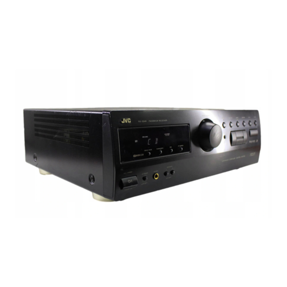
RX-554RBK
CD
TV
VCR
AUDIO
DAP MODE
3D-PHONIC SURROUND
TAPE
1
2
3
TUNER/
EFFECT
DELAY
TEST
BAND
4
5
6
–
+
SEA MODE
REAR
VCR
7/P
8
9
–
+
SEA
CENTER
VIDEO
10
+10
PRESET
PHONO
SOUND
ONE TOUCH
CONTROL
CD-DISC
OPERATION
–
+
–
+
TV CH
VCR CH
PTY SEARCH
DISPLAY
–
+
TV VOL.
TV/
VIDEO
–
+
PTY SELECT
–
+
VOLUME
MUTING
RM-SR554RU REMOTE CONTROL
STANDBY
STANDBY/ON
MASTER VOLUME
RX-554R
FM/MW/LW RECEIVER
–
DISPLAY MODE
TA/ NEWS /INFO
EON
PTY SEARCH
POWER
PHONES
SPEAKERS
1
2
_ON —OFF
_ON —OFF
INSTRUCTIONS
BEDIENUNGSANLEITUNG
MANUEL D'INSTRUCTIONS
GEBRUIKSAANWIJZING
MANUAL DE INSTRUCCIONES
ISTRUZIONI
TUNER/BAND
PRESET SEA
SOURCE
SURROUND
ADJUST
SETTING
+
MEMORY
ONE TOUCH OPERATION
ENHANCED COMPULINK CONTROL SYSTEM
For Customer Use:
Enter below the Model No. and Serial
No. which are located either on the rear,
bottom or side of the cabinet. Retain this
information for future reference.
Model No.
Serial No.
LET0118-001A
[E, EE]
Advertisement
Table of Contents

Related Manuals for JVC RX-554RBK


Summary of Contents for JVC RX-554RBK
- Page 1 FM/MW/LW RECEIVER UKW/MW/LW-RECEIVER AMPLI/TUNER FM/PO/GO FM/MG/LG TUNER/VERSTERKER RECEPTOR FM/MW/LW RICEVITORE MF/OM/OL RX-554RBK AUDIO DAP MODE 3D-PHONIC SURROUND TAPE TUNER/ EFFECT DELAY TEST BAND – SEA MODE REAR – CENTER VIDEO PRESET PHONO SOUND ONE TOUCH CONTROL CD-DISC OPERATION – –...
- Page 2 L or coloured red. IF IN DOUBT - CONSULT A COMPETENT ELECTRICIAN. Per I’ltalia: “Si dichiara che il questo prodotto di marca JVC è conforme alle prescrizioni del Decreto Ministeriale n.548 del 28/08/95 pubblicato sulla Gazzetta Ufficiale della Repubblica Italiana n.301 del 28/12/95.”...
- Page 3 CAUTION To reduce the risk of electrical shocks, fire, etc.: 1. Do not remove screws, covers or cabinet. 2. Do not expose this appliance to rain or moisture. ACHTUNG Zur Verhinderung von elektrischen Schlägen, Brandgefahr, usw: 1. Keine Schrauben lösen oder Abdeckungen enternen und nicht das Gehäuse öffnen.
- Page 4 Caution –– POWER switch and STANDBY/ON This apparatus is provided with a POWER switch to be able to minimize power consumption for safe use. Therefore, 1. When doing initial setting, complete all the connections required, connect the mains plug into the wall outlet, and set the switch to ON.
- Page 5 Spacing 15 cm or more Abstand von 15 cm oder mehr Dégagement de 15 cm ou plus Minstens 15 cm tussenruimte Espacio de 15 cm o más 15 cm di distanza o più RX-554RBK Floor Boden Plancher Vloer Piso Pavimento...
-
Page 6: Table Of Contents
Using the Preset SEA Modes ... 24 Selecting Your Favorite SEA Mode ... 24 Activating the Surround Sounds ... 26 Using JVC 3D-PHONIC Modes ... 27 Using the DAP Modes ... 29 Speaker Arrangements for Surround Modes ... 31 Preparing for Surround Modes ... 32 Using Surround Modes ... -
Page 7: Parts Identification
Parts Identification Become familiar with the buttons and controls on the receiver before use. 4 5 6 RX-554R FM/MW/LW RECEIVER DISPLAY MODE TA/ NEWS /INFO STANDBY POWER PHONES SPEAKERS _ON —OFF _ON —OFF STANDBY/ON ™ AUDIO DAP MODE 3D-PHONIC SURROUND... -
Page 8: Getting Started
Getting Started This section explains how to connect stereo components and speakers to the receiver, and how to connect the power supply. Before Installation General • Be sure your hands are dry. • Turn the power off to all components. -
Page 9: Connecting The Fm And Am (Mw/Lw) Antennas
Connecting the FM and AM (MW/LW) Antennas FM Antenna Connections IA L FM Antenna Extend the FM antenna horizontally. ANTENNA FM 75 COAXIAL Outside FM Antenna wire LOOP A. Using the Supplied FM Antenna The FM antenna provided can be connected to the FM 75 temporary measure. -
Page 10: Connecting The Speakers
Getting Started Connecting the Speakers You can connect the following speakers: • Two sets of front speakers to produce normal stereo sound • One set of rear speakers to enjoy the surround effect • One center speaker to produce more effective surround effect (to make human voices outstanding) For each speaker, connect one end of the speaker signal cable (not supplied) to the speaker terminal on the rear panel and the other end to the speaker. - Page 11 The required speaker impedance of the front speakers differs depending on whether or not a center and/or rear speakers are connected at the same time. Since there are four possible speaker connections with the receiver, check which one fits your case and use the speaker with the impedance described below.
-
Page 12: Audio/Video Component Connections
Turntable If your audio components have a COMPU LINK-3 terminals The COMPU LINK remote control system allows you to control other JVC audio components from the receiver or vice versa. For detailed information about the COMPU LINK-3 remote control system, see page... -
Page 13: Connecting The Power Cord
Connecting the Power Cord Before plugging the receiver into an AC outlet, make sure that all connections have been made. 1. Plug the power cord into an AC outlet. POWER to set it in the _ _ _ _ _ ON position. -
Page 14: Basic Operations
POWER to set it in the — OFF position on the front panel. Note: When you press one of the source buttons on the remote control marked with an asterisk (*), the receiver automatically turns on. -
Page 15: Adjusting The Volume
Adjusting the Volume On the front panel: To increase the volume, turn MASTER VOLUME clockwise. To decrease the volume, turn it counterclockwise. When you turn MASTER VOLUME rapidly, the volume level also changes rapidly. When you turn MASTER VOLUME slowly, the volume level also changes slowly. -
Page 16: Recording A Source
Basic Operations Recording a Source You can record any source playing through the receiver to a cassette deck connected to the TAPE jacks and the VCR connected to the VCR jacks at the same time. While recording, you can listen to the selected sound source at whatever sound level you like, without affecting the sound levels of the recording. -
Page 17: Basic Settings
• Select “OFF” to cancel it. The indicator goes off. Using the Sleep Timer Using the Sleep Timer, you can fall asleep to music and know the receiver will turn off by itself rather than play all night. On the front panel only : 1. -
Page 18: Selecting The Center Speaker Size
Basic Settings When the shut-off time comes The receiver turns off automatically. To check or change the time remaining until the shut-off time 1. Press SETTING, if necessary, so that the Control % / fi / @ / # buttons work for setting the Sleep Timer. -
Page 19: One Touch Operation
This receiver can memorize the optimum sound settings for each playing source. About the One Touch Operation JVC’s One Touch Operation function is used to assign and store different sound settings for each different playing source. By using this function, you do not have to change the settings every time you change the source. -
Page 20: Receiving Radio Broadcasts
Receiving Radio Broadcasts You can browse through all the stations or use the preset function to go immediately to a particular station. Tuning in Stations Manually On the front panel only : 1. Press TUNER/BAND. The indicator above the button lights up. Each time you press the button, the band alternates between FM and AM (MW/LW). - Page 21 5. Repeat steps 1 to 4 until you store all the stations you want. To cancel a stored preset station Storing a new station on a used number erases the previously stored one. To tune in a preset station On the front panel: 1.
-
Page 22: Selecting The Fm Reception Mode
When tuned to an FM station which provides the RDS service, the RDS indicator lights up on the display. With the receiver, you can receive the following types of RDS signals. PS (Program Service) : PTY (Program Type) : RT (Radio Text) : EON (Enhanced Other Network): see page 22. -
Page 23: What Information Can Rds Signals Provide
About characters shown on the display When the display shows PS, PTY, or RT signals, the following characters are used. • The display cannot differentiate upper case and lower case letters and always uses upper case letters. • The display cannot show accented letters, “A”, for instance, may stand for accented “A’s”... -
Page 24: Searching For A Program By Pty Codes
3. Press PTY SEARCH again. While searching, “SEARCH” and the selected PTY code alternate on the display. The receiver searches 40 preset channels, stops when it finds the one you have selected, and tunes in that station. To continue searching after the first stop: Press PTY SEARCH again while the indications on the display are flashing. - Page 25 3. Press PTY SEARCH again. While searching, “SEARCH” and the selected PTY code alternate on the display. The receiver searches 40 preset channels, stops when it finds the one you have selected, and tunes in that station. To continue searching after the first stop: Press PTY SEARCH again while the indications on the display are flashing.
- Page 26 Receiving Radio Broadcasts Descriptions of the PTY codes: « NEWS ALARM TEST DOCUMENT FOLK M (FOLK MUSIC) OLDIES NATIONAL (NATIONAL MUSIC) COUNTRY JAZZ LEISURE TRAVEL PHONE IN RELIGION SOCIAL A (SOCIAL AFFAIRS) CHILDREN FINANCE » « AFFAIRS INFO (INFORMATION) SPORT EDUCATE (EDUCATION) DRAMA...
-
Page 27: Switching To A Broadcast Program Of Your Choice Temporarily
The TEST signal is used for equipment test — whether it can receive the ALARM signal correctly. The TEST signal makes the receiver work in the same way as the ALARM signal does. If an TEST signal is received, the receiver automatically switches to the station broadcasting the TEST signal. - Page 28 The indicator of received PTY code starts flashing. When the program is over, the receiver goes back to the previously selected source, but still remains in EON standby mode. The indicator of received PTY code stops flashing and remains lit.
-
Page 29: Using The Preset Sea Modes
Using the Preset SEA Modes The preset SEA (Sound Effect Amplifier) modes give you control of the way your music sounds. Selecting Your Favorite SEA Mode On the front panel: 1. Press PRESET SEA so that the Control % % % % % / fi fi fi fi fi / @ @ @ @ @ / # # # # # buttons work for preset SEA setting. - Page 30 Using the Preset SEA Modes From the remote control: 1. Press SOUND CONTROL so that 10 keys work for adjusting the sound. 2. Press SEA MODE until the preset SEA mode you want appears on the display. The previously selected mode is recalled (at its previous effect level) and is shown on the display.
-
Page 31: Activating The Surround Sounds
Activating the Surround Sounds The built-in surround processor provides three groups of programs — JVC 3D-PHONIC mode, DAP (Digital Acoustic Processor) mode, and surround modes (Dolby Surround and JVC Theater Surround). You cannot use the DAP mode and surround mode at the same time. When you turn on the DAP mode, the surround mode is turned off (if it has been on), and vice versa. -
Page 32: Using Jvc 3D-Phonic Modes
Activating the Surround Sounds Using JVC 3D-PHONIC Modes When using JVC 3D-PHONIC modes, you need only two front speakers to reproduce the soundtracks of video software bearing the mark The 3D-PHONIC modes give you very realistic surround effects as if the sound is reproduced through the Dolby Surround decoder. - Page 33 6. Press Control @ @ @ @ @ / # # # # # to adjust the effect level. Each time you press the button, the effect level changes as follows: EFFECT 1 EFFECT 2 EFFECT 5 As the number increases, the effect of the selected 3D- PHONIC mode becomes stronger.
-
Page 34: Using The Dap Modes
Activating the Surround Sounds Using the DAP Modes You can use five DAP modes — “Dance Club, Live Club, Hall, Pavilion, and Headphones.” These modes (except “Headphones”) require the front speakers and the rear speakers, but do not require a center speaker to enlarge the sound field. Among the DAP modes, “Headphones”... - Page 35 6. Press Control @ @ @ @ @ / # # # # # to adjust the rear speaker output level. • Pressing Control @ decreases the output level up to –10 dB. • Pressing Control # increases the output level up to +10 dB.
-
Page 36: Speaker Arrangements For Surround Modes
Activating the Surround Sounds With this receiver, you can use two types of the surround modes — Dolby Surround and JVC Theater Surround. Speaker Arrangements for Surround Modes The following illustrations show how to obtain the optimum sound environment for various surround modes settings. -
Page 37: Preparing For Surround Modes
Preparing for Surround Modes Once you have set the surround modes, you can use the same adjustment every time you want to activate the surrround mode you want. The receiver memorizes surround adjustments for each mode. On the front panel: 1. - Page 38 Activating the Surround Sounds 5. Press Control @ @ @ @ @ / # # # # # to select the center mode. Each time you press the button, the center modes change as follows: WIDE NORMAL WIDE Select this mode when the center speaker can reproduce the bass better than the front speakers.
- Page 39 Control @ @ @ @ @ / # # # # # twice to stop the test tone. If you have selected JVC Theater Surround, go to the following steps. 11. Press Control % % % % % / fi fi fi fi fi until “–EFFECT+” appears on the display.
- Page 40 Pressing + increases the output level up to +10 dB. 6. Press TEST again to stop the test tone. If you have selected JVC Theater Surround, go to the following steps. 7. Press EFFECT to adjust the effect level. Each time you press the button, the effect level changes...
-
Page 41: Using Surround Modes
Using Surround Modes Once you have adjusted the surround mode, you can use the same adjustments every time you want to enjoy Surround Modes. From the front panel: 1. Press SURROUND so that the Control % % % % % / fi fi fi fi fi buttons work for selecting the surround/DAP/3D-PHONIC modes. -
Page 42: Compu Link Remote Control System
COMPU LINK Remote Control System The COMPU LINK remote control system allows you to operate JVC audio components through the remote sensor on the receiver. To use this remote control system, you need to connect JVC audio components through the COMPU LINK-3 (SYNCHRO) jacks with the cable (monaural mini-plug supplied... -
Page 43: Operating Other Components
Operating Other Components You can operate JVC audio and video components with this receiver’s remote control. To operate these components with the remote control, first select a source with the source buttons on the remote control. Then, operate that source using the remote control. - Page 44 Operating Other Components IMPORTANT: To operate JVC video components using this remote control: • Aim the remote control directly at the remote sensor on the VCR or TV, not on the receiver. 7 7 7 7 7 After pressing VCR, you can perform the following operations on the VCR: Starts playback.
-
Page 45: Troubleshooting
Troubleshooting Use this chart to help you solve daily operational problems. If there is any problem you cannot solve, contact your JVC service center. PROBLEM The display does not light up. No sound from speakers. “OVERLOAD” starts flashing on the display. -
Page 46: Specifications
8 ohms at 1 kHz, with no more than 0.8 % total harmonic distortion. ohms at 1 kHz, with no more than 0.8 % total harmonic distortion. ohms at 1kHz, with no more than 0.8 % total harmonic distortion. (* Measured by JVC Audio Analysis System) - Page 47 FM tuner (IHF) Tuning Range ... 87.5 MHz to 108.0 MHz Usable Sensitivity ... 12.7 dBf (1.2 µV/75 ohms) 50 dB Quieting Sensitivity ... Monaural ... 16.3 dBf (1.8 µV/75 ohms) Signal-to-Noise Ratio (IHF-A weighted) ... Monaural ... 80 dB at 85 dBf Total Harmonic Distortion ...
- Page 48 VICTOR COMPANY OF JAPAN, LIMITED 0298OFMMDWJEM EN, GE, FR, NL, SP, IT...
Need help?
Do you have a question about the RX-554RBK and is the answer not in the manual?
Questions and answers