Comunello BORDER 400 Installation And User Manual
Hide thumbs
Also See for BORDER 400:
- Installation and user manual (32 pages) ,
- Installation and user manual (60 pages)
Table of Contents
Advertisement
Quick Links
INSTALLATION AND USER MANUAL
BORDER 400 / 600
EC DECLARATION OF CONFORMITY
The undersigned, Mr LUCA COMUNELLO, representative of the following manufacturer
F.lli COMUNELLO spa
Via Cassola 64, 36027 Rosà (VI) Italy
DECLARES that with regard to the device hereinafter described:
Description
Manually operated barrier 3/4/5/6 metres
Model
BORDER W/ MOTOR 400 / 600
complies with the legislative provisions that transpose the following directives:
• 2006/42/EC (Machinery Directive)
• 2011/305/EEC (CPR Regulation)
• 2011/65/EU (RoHS Directive)
Rosà (VI) – Italy
28-10-2021
Moreover, the undersigned also declares that it is prohibited to place the machinery into operation until such time as the machine into
which it will be incorporated, or of which it will become a component, has been identified and declared as conforming to the provisions of
Directive 2006/42/EC and the national legislation transposing said directive.
LUCA COMUNELLO
Legal Representative of FRATELLI COMUNELLO s.p.a.
Fratelli Comunello S.p.A.
Company with certified Quality Management System
UNI EN ISO 9001:2015.
20
COMUNELLO ®Copyright 2021 - All rights reserved
Advertisement
Table of Contents

Related Manuals for Comunello BORDER 400


Summary of Contents for Comunello BORDER 400
- Page 1 INSTALLATION AND USER MANUAL BORDER 400 / 600 EC DECLARATION OF CONFORMITY The undersigned, Mr LUCA COMUNELLO, representative of the following manufacturer F.lli COMUNELLO spa Via Cassola 64, 36027 Rosà (VI) Italy DECLARES that with regard to the device hereinafter described:...
-
Page 2: Table Of Contents
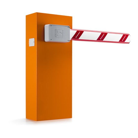
• In case of a fault that cannot be resolved using the information in this manual, contact the help service. 2 MODELS AND PRODUCTS DESCRIPTION DESCRIPTION Robust and easy to install, the manually operated BORDER barrier system is suitable for private, public or industrial use. COMUNELLO ®Copyright 2021 - All rights reserved... -
Page 3: Typical Installation
BORDER 400 W/MOTOR BORDER 400 W/MOTOR BORDER 600 W/MOTOR BORDER 600 W/MOTOR Maximum boom length Protection rating IP 44 Operating temp. -40°C to +50°C Mass 50 Kg 51 Kg 58 Kg 59 Kg COMUNELLO ®Copyright 2021 - All rights reserved... -
Page 4: Installation
• All devices to be installed are in a protected location in order to minimise the risk of accidental impact. • If necessary, create a pedestrian entrance well clear of the operating range of the barrier boom. COMUNELLO ®Copyright 2021 - All rights reserved... -
Page 5: Limits Of Use
INSTALLATION OF THE MANUALLY OPERATED BORDER BARRIER SYSTEM 4.4.1 INSTALLATION • Remove the front cover using the supplied key (FIG. 4). • Position the barrier on the counter plate. Secure the pedestal with the nuts and washers supplied (FIG. 5). COMUNELLO ®Copyright 2021 - All rights reserved... - Page 6 FIG. 5 Fitting the springs: The manually operated BORDER 400-600 barrier system features a single- or double-spring mechanism. The spring assembly must be mounted in the corresponding bore according to the length of the boom as shown in the following table: •...
- Page 7 FIG. 6A FIG. 6B Double spring installation only on BORDER 600 with skirt • Install the double spring as shown in figure 6C (installation example with boom on the right). FIG. 6C COMUNELLO ®Copyright 2021 - All rights reserved...
- Page 8 Installation of locking system and boom: • Mount the supplied boom holder and locking system as shown in figures 7A-7B-7C-7D. FIG. 7A FIG. 7B FIG. 7C FIG. 7D COMUNELLO ®Copyright 2021 - All rights reserved...
- Page 9 • Secure the plug to one end of the boom as shown in figure 9. FIG. 8 FIG. 9 • Insert the boom into the corresponding boom holder and secure it with the 4 screws as shown in figure 10. FIG. 10 COMUNELLO ®Copyright 2021 - All rights reserved...
-
Page 10: Adjustment Of Mechanical Stops
• Adjust the opening stop by turning the screw so that it rests on the spring attachment plate in the vertical boom position and secure the screw using its locknut as shown in Figure 13B. COMUNELLO ®Copyright 2021 - All rights reserved... - Page 11 FIG. 13A FIG. 13B Operation of the locking system: • To release the system, pull and turn the knob as shown in figures 14A and 14B. FIG. 14A COMUNELLO ®Copyright 2021 - All rights reserved...
- Page 12 FIG. 14B FIG. 14C COMUNELLO ®Copyright 2021 - All rights reserved...
- Page 13 FIG. 14D FIG. 14E • To re-lock the system, turn the knob in the opposite direction. COMUNELLO ®Copyright 2021 - All rights reserved...
-
Page 14: Installation Of The Pendulum Support
• Cut the sleeve to the length required to install the pendulum support (FIG. 15). • Insert the sleeve and secure the pendulum support (FIG. 17). • Replace the boom end plug. FIG. 15 FIG. 16A FIG. 16B FIG. 17 COMUNELLO ®Copyright 2021 - All rights reserved... -
Page 15: Installation Of The Skirt
• Drill the marked points with a Ø 6mm bit as illustrated in fig.19 B. • Secure the skirt to the boom as shown in fig.20. • Replace the boom end plug. FIG. 18 FIG. 19 100 mm 200 mm 200 mm COMUNELLO ®Copyright 2021 - All rights reserved... -
Page 16: Testing
The Warranty is valid and binding for COMUNELLO only if the product is correctly assembled and serviced in accordance with the rules of installation and safety indicated in the documentation provided by COMUNELLO or in any case available on the website http://www.comunello.com/it/corporate/condizioni-generali/... - Page 17 The warranty does not cover the cost of consumables, in any case COMUNELLO accrues credit for the intervention carried out at the client premises, in the event the latter proves useless because the warranty was no longer valid or because the client had used the COMUNELLO product in a negligent, careless or inexperienced manner, such that correct use of the product would have prevented the need for installation.
- Page 18 NOTES...
- Page 19 NOTES...
- Page 20 NOTES...
- Page 21 FRATELLI COMUNELLO S.P.A. AUTOMATION GATE DIVISION Via Cassola, 64 - C.P. 79 36027 Rosà, Vicenza, Italy Tel. +39 0424 585111 Fax +39 0424 533417 info@comunello.it www.comunello.com...
Need help?
Do you have a question about the BORDER 400 and is the answer not in the manual?
Questions and answers