Table of Contents
Advertisement
Quick Links
Advertisement
Chapters
Table of Contents

Related Manuals for Textron Aviation Cessna 172S NAV III Skyhawk SP


Summary of Contents for Textron Aviation Cessna 172S NAV III Skyhawk SP
- Page 1 172S NAV III Skyhawk SP Information Manual MODEL 172S NAV III AVIONICS OPTION - KAP 140 AUTOPILOT Serials 172S9810 thru 172S10467 and 172S10469 thru 172S10506 and 172S10508 thru 172S10639 and 172S10641 thru 172S10655 COPYRIGHT © 2016 CESSNA AIRCRAFT COMPANY WICHITA, KANSAS, USA...
- Page 3 CESSNA INTRODUCTION MODEL 172S NAV III KAP 140 AUTOPILOT NOTICE AT THE TIME OF ISSUANCE, THIS INFORMATION MANUAL WAS AN EXACT DUPLICATE OF THE OFFICIAL PILOT’S OPERATING HANDBOOK AND FAA APPROVED AIRPLANE FLIGHT MANUAL AND IS TO BE USED FOR GENERAL PURPOSES ONLY. WILL KEPT CURRENT...
- Page 4 INTRODUCTION CESSNA MODEL 172S NAV III KAP 140 AUTOPILOT PERFORMANCE - SPECIFICATIONS *SPEED: Maximum at Sea Level ......126 KNOTS Cruise, 75% Power at 8500 Feet.
- Page 5 CESSNA INTRODUCTION MODEL 172S NAV III KAP 140 AUTOPILOT PERFORMANCE - SPECIFICATIONS (Continued) STANDARD EMPTY WEIGHT....1663 POUNDS MAXIMUM USEFUL LOAD ..... . . 895 POUNDS BAGGAGE ALLOWANCE .
- Page 7 CESSNA INTRODUCTION MODEL 172S NAV III KAP 140 AUTOPILOT Cessna Aircraft Company Model 172S NAV III AVIONICS - KAP 140 AUTOPILOT Serials 172S9810 thru 172S10467 and 172S10469 thru 172S10506 and 172S10508 thru 172S10639 and 172S10641 thru 172S10655 THIS MANUAL INCORPORATES INFORMATION ISSUED IN THE PILOT'S OPERATING HANDBOOK...
- Page 9 CESSNA INTRODUCTION MODEL 172S NAV III KAP 140 AUTOPILOT TABLE OF CONTENTS SECTION GENERAL ..........1 LIMITATIONS.
-
Page 11: Table Of Contents
CESSNA SECTION 1 MODEL 172S NAV III GENERAL KAP 140 AUTOPILOT GENERAL TABLE OF CONTENTS Page Three View - Normal Ground Attitude ......1-3 Introduction . -
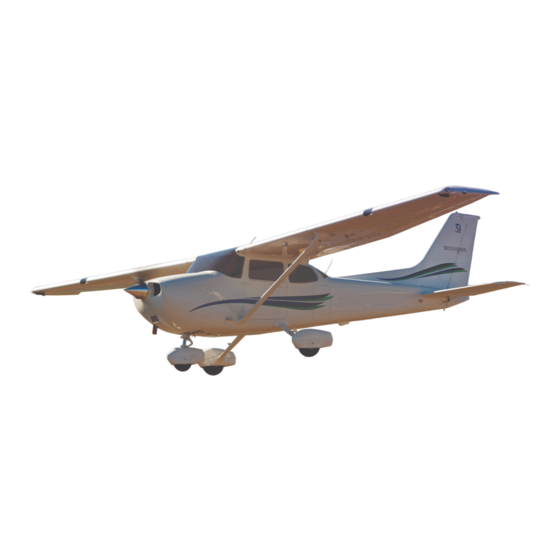
Page 13: Three View - Normal Ground Attitude
CESSNA SECTION 1 MODEL 172S NAV III GENERAL KAP 140 AUTOPILOT THREE VIEW - NORMAL GROUND ATTITUDE Figure 1-1* (Sheet 1 of 2) 172SPHAUS-05 U.S. - Page 14 SECTION 1 CESSNA GENERAL MODEL 172S NAV III KAP 140 AUTOPILOT THREE VIEW - NORMAL GROUND ATTITUDE NOTE • Wing span shown with standard strobe lights installed. • Wheel base length is 65.0 inches. • Propeller ground clearance is 11.25 inches. •...
-
Page 15: Introduction
CESSNA SECTION 1 MODEL 172S NAV III GENERAL KAP 140 AUTOPILOT INTRODUCTION This POH contains 9 sections, and includes the material required to be furnished to the pilot by 14 CFR 23. It also contains supplemental data supplied by Cessna Aircraft Company. Section 1 provides basic data and information of general interest. -
Page 16: Fuel
SECTION 1 CESSNA GENERAL MODEL 172S NAV III KAP 140 AUTOPILOT DESCRIPTIVE DATA (Continued) FUEL WARNING USE OF UNAPPROVED FUELS MAY RESULT IN DAMAGE TO THE ENGINE AND FUEL SYSTEM COMPONENTS, RESULTING IN POSSIBLE ENGINE FAILURE. Approved Fuel Grades (and Colors): 100LL Grade Aviation Fuel (Blue) Grade Aviation Fuel (Green) NOTE... -
Page 17: Oil
CESSNA SECTION 1 MODEL 172S NAV III GENERAL KAP 140 AUTOPILOT DESCRIPTIVE DATA (Continued) OIL SPECIFICATION MIL-L-6082 or SAE J1966 Aviation Grade Straight Mineral Oil: Used when the airplane was delivered from the factory and should be used to replenish the supply during the first 25 hours. This oil should be drained and the filter changed after the first 25 hours of operation. -
Page 18: Maximum Certificated Weights
SECTION 1 CESSNA GENERAL MODEL 172S NAV III KAP 140 AUTOPILOT DESCRIPTIVE DATA (Continued) MAXIMUM CERTIFICATED WEIGHTS Ramp Weight: Normal Category ......2558 POUNDS Utility Category . -
Page 19: Standard Airplane Weights
CESSNA SECTION 1 MODEL 172S NAV III GENERAL KAP 140 AUTOPILOT DESCRIPTIVE DATA (Continued) STANDARD AIRPLANE WEIGHTS Standard Empty Weight ......1663 POUNDS Maximum Useful Load, Normal Category . -
Page 20: Symbols, Abbreviations And Terminology
SECTION 1 CESSNA GENERAL MODEL 172S NAV III KAP 140 AUTOPILOT SYMBOLS, ABBREVIATIONS AND TERMINOLOGY GENERAL AIRSPEED TERMINOLOGY AND SYMBOLS KCAS Knots Calibrated Airspeed is indicated airspeed corrected for position and instrument error and expressed in knots. Knots calibrated airspeed is equal to KTAS in standard atmosphere at sea level. -
Page 21: Meteorological Terminology
CESSNA SECTION 1 MODEL 172S NAV III GENERAL KAP 140 AUTOPILOT SYMBOLS, ABBREVIATIONS AND TERMINOLOGY (Continued) METEOROLOGICAL TERMINOLOGY Outside Air Temperature is the free air static temperature. It may be expressed in either degrees Celsius or degrees Fahrenheit. Standard Temperature Standard Temperature is 15°C at sea level pressure altitude and decreases by 2°C for each 1000 feet of altitude. - Page 22 SECTION 1 CESSNA GENERAL MODEL 172S NAV III KAP 140 AUTOPILOT SYMBOLS, ABBREVIATIONS AND TERMINOLOGY (Continued) ENGINE POWER TERMINOLOGY (Continued) Rich Mixture Increased proportion of fuel in the fuel-air mixture supplied to the engine. As air density increases, the amount of fuel required by the engine increases for a given throttle setting.
-
Page 23: Airplane Performance And Flight Planning Terminology
CESSNA SECTION 1 MODEL 172S NAV III GENERAL KAP 140 AUTOPILOT SYMBOLS, ABBREVIATIONS AND TERMINOLOGY (Continued) AIRPLANE PERFORMANCE AND FLIGHT PLANNING TERMINOLOGY Demonstrated Crosswind Velocity Demonstrated Crosswind Velocity is the velocity of the crosswind component for which adequate control of the airplane during takeoff and landing was actually demonstrated during certification tests. -
Page 24: Weight And Balance Terminology
SECTION 1 CESSNA GENERAL MODEL 172S NAV III KAP 140 AUTOPILOT SYMBOLS, ABBREVIATIONS AND TERMINOLOGY (Continued) WEIGHT AND BALANCE TERMINOLOGY Reference Datum Reference Datum is an imaginary vertical plane from which all horizontal distances are measured for balance purposes. Station Station is a location along the airplane fuselage given in terms of the distance from the reference datum. - Page 25 CESSNA SECTION 1 MODEL 172S NAV III GENERAL KAP 140 AUTOPILOT SYMBOLS, ABBREVIATIONS AND TERMINOLOGY (Continued) WEIGHT AND BALANCE TERMINOLOGY (Continued) Basic Empty Weight Basic Empty Weight is the standard empty weight plus the weight of optional equipment. Useful Load Useful Load is the difference between ramp weight and the basic empty weight.
-
Page 26: Metric/Imperial/U.s. Conversion Charts
SECTION 1 CESSNA GENERAL MODEL 172S NAV III KAP 140 AUTOPILOT METRIC/IMPERIAL/U.S. CONVERSION CHARTS The following charts have been provided to help international operators convert U.S. measurement supplied with the Pilot’s Operating Handbook into metric and imperial measurements. The standard followed for measurement units shown is the National Institute of Standards Technology (NIST), Publication 811, "Guide for the Use of the International System of Units (SI)."... -
Page 27: Weight Conversions
CESSNA SECTION 1 MODEL 172S NAV III GENERAL KAP 140 AUTOPILOT WEIGHT CONVERSIONS Figure 1-2* (Sheet 1 of 2) 172SPHAUS-05 1-17 U.S. - Page 28 SECTION 1 CESSNA GENERAL MODEL 172S NAV III KAP 140 AUTOPILOT WEIGHT CONVERSIONS Figure 1-2 (Sheet 2) 172SPHAUS-05 1-18 U.S.
-
Page 29: Length Conversions
CESSNA SECTION 1 MODEL 172S NAV III GENERAL KAP 140 AUTOPILOT LENGTH CONVERSIONS Figure 1-3* (Sheet 1 of 4) 172SPHAUS-05 1-19 U.S. - Page 30 SECTION 1 CESSNA GENERAL MODEL 172S NAV III KAP 140 AUTOPILOT LENGTH CONVERSIONS Figure 1-3 (Sheet 2) 172SPHAUS-05 1-20 U.S.
- Page 31 CESSNA SECTION 1 MODEL 172S NAV III GENERAL KAP 140 AUTOPILOT LENGTH CONVERSIONS Figure 1-3* (Sheet 3) 172SPHAUS-05 1-21 U.S.
- Page 32 SECTION 1 CESSNA GENERAL MODEL 172S NAV III KAP 140 AUTOPILOT LENGTH CONVERSIONS Figure 1-3 (Sheet 4) 172SPHAUS-05 1-22 U.S.
-
Page 33: Distance Conversions
CESSNA SECTION 1 MODEL 172S NAV III GENERAL KAP 140 AUTOPILOT DISTANCE CONVERSIONS Figure 1-4 172SPHAUS-05 1-23 U.S. -
Page 34: Volume Conversions
SECTION 1 CESSNA GENERAL MODEL 172S NAV III KAP 140 AUTOPILOT VOLUME CONVERSIONS Figure 1-5* (Sheet 1 of 3) 172SPHAUS-05 1-24 U.S. - Page 35 CESSNA SECTION 1 MODEL 172S NAV III GENERAL KAP 140 AUTOPILOT VOLUME CONVERSIONS Figure 1-5* (Sheet 2) 172SPHAUS-05 1-25 U.S.
- Page 36 SECTION 1 CESSNA GENERAL MODEL 172S NAV III KAP 140 AUTOPILOT VOLUME CONVERSIONS Figure 1-5 (Sheet 3) 172SPHAUS-05 1-26 U.S.
-
Page 37: Temperature Conversions
CESSNA SECTION 1 MODEL 172S NAV III GENERAL KAP 140 AUTOPILOT TEMPERATURE CONVERSIONS Figure 1-6* 172SPHAUS-05 1-27 U.S. -
Page 38: Pressure Conversion
SECTION 1 CESSNA GENERAL MODEL 172S NAV III KAP 140 AUTOPILOT PRESSURE CONVERSION HECTOPASCALS TO INCHES OF MERCURY Figure 1-7* 172SPHAUS-05 1-28 U.S. -
Page 39: Volume To Weight Conversion
CESSNA SECTION 1 MODEL 172S NAV III GENERAL KAP 140 AUTOPILOT VOLUME TO WEIGHT CONVERSION Figure 1-8 172SPHAUS-05 1-29 U.S. - Page 40 SECTION 1 CESSNA GENERAL MODEL 172S NAV III KAP 140 AUTOPILOT QUICK CONVERSIONS Figure 1-9 172SPHAUS-05 1-30 U.S.
- Page 41 CESSNA SECTION 2 MODEL 172S NAV III OPERATING LIMITATIONS KAP 140 AUTOPILOT OPERATING LIMITATIONS TABLE OF CONTENTS Page Introduction ..........2-3 Airspeed Limitations .
-
Page 43: Introduction
CESSNA SECTION 2 MODEL 172S NAV III OPERATING LIMITATIONS KAP 140 AUTOPILOT INTRODUCTION Section 2 includes operating limitations, instrument markings, and basic placards necessary for the safe operation of the airplane, its engine, standard systems and standard equipment. The limitations included in this section and in Section 9 have been approved by the Federal Aviation Administration. -
Page 44: Airspeed Limitations
SECTION 2 CESSNA OPERATING LIMITATIONS MODEL 172S NAV III KAP 140 AUTOPILOT AIRSPEED LIMITATIONS Airspeed limitations and their operational significance are shown in Figure 2-1. Maneuvering speeds shown apply to normal category operations. The utility category maneuvering speed is 98 KIAS at 2200 pounds. -
Page 45: Airspeed Indicator Markings
CESSNA SECTION 2 MODEL 172S NAV III OPERATING LIMITATIONS KAP 140 AUTOPILOT AIRSPEED INDICATOR MARKINGS Airspeed indicator markings and their color code significance are shown in Figure 2-2. AIRSPEED INDICATOR MARKINGS KIAS VALUE OR MARKING SIGNIFICANCE RANGE Red Arc* 20 - 40 Low airspeed warning. -
Page 46: Powerplant Limitations
SECTION 2 CESSNA OPERATING LIMITATIONS MODEL 172S NAV III KAP 140 AUTOPILOT POWERPLANT LIMITATIONS Engine Manufacturer: Textron Lycoming Engine Model Number: IO-360-L2A Maximum Power: 180 BHP Rating Engine Operating Limits for Takeoff and Continuous Operations: Maximum Engine Speed:......2700 RPM NOTE The static RPM range at full throttle is 2300 - 2400 RPM. -
Page 47: Powerplant Instrument Markings
CESSNA SECTION 2 MODEL 172S NAV III OPERATING LIMITATIONS KAP 140 AUTOPILOT POWERPLANT INSTRUMENT MARKINGS Powerplant instrument markings and their color code significance are shown in Figure 2-3. Operation with indications in the red range is prohibited. Avoid operating with indicators in the yellow range. POWERPLANT INSTRUMENT MARKINGS GREEN ARC RED LINE... -
Page 48: Weight Limits
SECTION 2 CESSNA OPERATING LIMITATIONS MODEL 172S NAV III KAP 140 AUTOPILOT WEIGHT LIMITS NORMAL CATEGORY Maximum Ramp Weight: ..... . 2558 POUNDS Maximum Takeoff Weight: . -
Page 49: Center Of Gravity Limits
CESSNA SECTION 2 MODEL 172S NAV III OPERATING LIMITATIONS KAP 140 AUTOPILOT CENTER OF GRAVITY LIMITS NORMAL CATEGORY Center Of Gravity Range: Forward: 35.0 inches aft of datum at 1950 pounds or less, with straight line variation to 41.0 inches aft of datum at 2550 pounds. -
Page 50: Maneuver Limits
SECTION 2 CESSNA OPERATING LIMITATIONS MODEL 172S NAV III KAP 140 AUTOPILOT MANEUVER LIMITS NORMAL CATEGORY This airplane is certificated in both the normal and utility category. The normal category is applicable to aircraft intended for non aerobatic operations. These include any maneuvers incidental to normal flying, stalls (except whip stalls), lazy eights, chandelles, and turns in which the angle of bank is not more than 60°. -
Page 51: Flight Load Factor Limits
CESSNA SECTION 2 MODEL 172S NAV III OPERATING LIMITATIONS KAP 140 AUTOPILOT MANEUVER LIMITS (Continued) UTILITY CATEGORY (Continued) Aerobatics that may impose high loads should not be attempted. The important thing to bear in mind in flight maneuvers is that the airplane is clean in aerodynamic design and will build up speed quickly with the nose down. -
Page 52: Kinds Of Operations Limits
SECTION 2 CESSNA OPERATING LIMITATIONS MODEL 172S NAV III KAP 140 AUTOPILOT KINDS OF OPERATIONS LIMITS The Cessna 172S Nav III airplane is approved for day and night, VFR and IFR operations. Flight into known icing conditions is prohibited. The minimum equipment for approved operations required under the Operating Rules are defined by 14 CFR 91 and 14 CFR 135, as applicable. -
Page 53: Kinds Of Operations Equipment List
CESSNA SECTION 2 MODEL 172S NAV III OPERATING LIMITATIONS KAP 140 AUTOPILOT KINDS OF OPERATIONS EQUIPMENT LIST KIND OF OPERATION System, Instrument, Equipment and/or Function COMMENTS PLACARDS AND MARKINGS 1 - 172S Nav III - KAP 140 Accessible to pilot in flight. - Page 54 SECTION 2 CESSNA OPERATING LIMITATIONS MODEL 172S NAV III KAP 140 AUTOPILOT KINDS OF OPERATIONS EQUIPMENT LIST (Continued) KIND OF OPERATION System, Instrument, Equipment and/or Function COMMENTS EQUIPMENT AND FURNISHINGS 1 - Seat Belt Assembly Each Seat Occupant 2 - Shoulder Harness Front Seat Occupants FLIGHT CONTROLS...
- Page 55 CESSNA SECTION 2 MODEL 172S NAV III OPERATING LIMITATIONS KAP 140 AUTOPILOT KINDS OF OPERATIONS EQUIPMENT LIST (Continued) KIND OF OPERATION System, Instrument, Equipment and/or Function COMMENTS LIGHTING 1 - PFD Bezel Lighting 2 - PFD Backlighting *Refer to Note 2. 3 - MFD Bezel Lighting 4 - MFD Backlighting *Refer to Note 3.
- Page 56 SECTION 2 CESSNA OPERATING LIMITATIONS MODEL 172S NAV III KAP 140 AUTOPILOT KINDS OF OPERATIONS EQUIPMENT LIST (Continued) KIND OF OPERATION System, Instrument, Equipment and/or Function COMMENTS NAVIGATION AND PITOT- STATIC SYSTEM 1 - G1000 Airspeed Indicator 2 - Standby Airspeed Indicator 3 - G1000 Altimeter 4 - Standby Altimeter 5 - G1000 Vertical Speed...
- Page 57 CESSNA SECTION 2 MODEL 172S NAV III OPERATING LIMITATIONS KAP 140 AUTOPILOT KINDS OF OPERATIONS EQUIPMENT LIST (Continued) KIND OF OPERATION System, Instrument, Equipment and/or Function COMMENTS VACUUM 1 - Engine Driven Vacuum Pump 2 - Vacuum Indicator ENGINE FUEL AND CONTROL 1 - Fuel Flow Indicator ENGINE INDICATING 1 - Tachometer (RPM)
-
Page 58: Fuel Limitations
SECTION 2 CESSNA OPERATING LIMITATIONS MODEL 172S NAV III KAP 140 AUTOPILOT FUEL LIMITATIONS Total Fuel: .......56.0 U.S. GALLONS (28.0 GALLONS per tank) Usable Fuel (all flight conditions): . -
Page 59: System Limitations
CESSNA SECTION 2 MODEL 172S NAV III OPERATING LIMITATIONS KAP 140 AUTOPILOT SYSTEM LIMITATIONS AUX AUDIO SYSTEM Use of the AUX AUDIO IN entertainment input is prohibited during takeoff and landing. Use of the AUX AUDIO IN entertainment audio input and portable electronic devices (PED), such as cellular telephones, games, cassette, CD or MP3 players, is prohibited under IFR unless the operator of the airplane has determined that the use of the Aux Audio... -
Page 60: G1000 Limitations
SECTION 2 CESSNA OPERATING LIMITATIONS MODEL 172S NAV III KAP 140 AUTOPILOT G1000 LIMITATIONS The current Garmin G1000 Cockpit Reference Guide (CRG) Part Number and System Software Version that must be available to the pilot during flight are displayed on the MFD AUX group, SYSTEM STATUS page. -
Page 61: Gps - Waas
CESSNA SECTION 2 MODEL 172S NAV III OPERATING LIMITATIONS KAP 140 AUTOPILOT G1000 LIMITATIONS (Continued) The COM 1/2 (split COM) function of the Audio Panel is not approved for use. During COM 1/2 operation, transmission by one crew member inhibits reception by the other crew member. The fuel quantity, fuel used and fuel remaining functions of the G1000 are supplemental information only and must be verified by the pilot. -
Page 62: Terrain Awareness And Warning System (Taws-B) (If Installed)
SECTION 2 CESSNA OPERATING LIMITATIONS MODEL 172S NAV III KAP 140 AUTOPILOT G1000 LIMITATIONS (Continued) TERRAIN AWARENESS AND WARNING SYSTEM (TAWS-B) (if installed) Use of the Terrain Awareness and Warning System (TAWS-B) to navigate to avoid terrain or obstacles is prohibited. TAWS-B is only approved as an aid to help the pilot to see-and-avoid terrain or obstacles. -
Page 63: Placards
CESSNA SECTION 2 MODEL 172S NAV III OPERATING LIMITATIONS KAP 140 AUTOPILOT PLACARDS The following information must be displayed in the form of composite or individual placards. 1. In full view of the pilot: (The "DAY-NIGHT-VFR-IFR" entry, shown on the example below, will vary with installed equipment). 2. - Page 64 SECTION 2 CESSNA OPERATING LIMITATIONS MODEL 172S NAV III KAP 140 AUTOPILOT PLACARDS (Continued) 3. On the fuel selector valve: 4. Near both fuel tank filler caps: (Continued Next Page) FAA APPROVED 172SPHAUS-05 2-24 U.S.
- Page 65 CESSNA SECTION 2 MODEL 172S NAV III OPERATING LIMITATIONS KAP 140 AUTOPILOT PLACARDS (Continued) 5. On flap control indicator: 6. In baggage compartment: (Continued Next Page) FAA APPROVED 172SPHAUS-05 2-25 U.S.
- Page 66 SECTION 2 CESSNA OPERATING LIMITATIONS MODEL 172S NAV III KAP 140 AUTOPILOT PLACARDS (Continued) 7. A calibration card must be provided to indicate the accuracy of the magnetic compass in 30° increments. 8. Molded on the oil filler cap/dipstick: 9. Silk-screened on the instrument panel directly above the PFD: (Continued Next Page) FAA APPROVED 172SPHAUS-05...
- Page 67 CESSNA SECTION 2 MODEL 172S NAV III OPERATING LIMITATIONS KAP 140 AUTOPILOT PLACARDS (Continued) 10. Silk-screened on the upper right instrument panel: 11. On auxiliary power plug door and second placard on battery box: 12. On the upper right side of the aft cabin partition: (Continued Next Page) FAA APPROVED 172SPHAUS-05...
- Page 68 SECTION 2 CESSNA OPERATING LIMITATIONS MODEL 172S NAV III KAP 140 AUTOPILOT PLACARDS (Continued) 13. On the center overhead flood light control switch: FAA APPROVED 172SPHAUS-05 2-28 U.S.
- Page 69 CESSNA SECTION 3 MODEL 172S NAV III EMERGENCY PROCEDURES KAP 140 AUTOPILOT EMERGENCY PROCEDURES TABLE OF CONTENTS Page Introduction ..........3-5 Airspeeds For Emergency Operations.
- Page 70 SECTION 3 CESSNA EMERGENCY PROCEDURES MODEL 172S NAV III KAP 140 AUTOPILOT TABLE OF CONTENTS (Continued) Page ABNORMAL LANDINGS....... . 3-16 Landing With A Flat Main Tire .
- Page 71 CESSNA SECTION 3 MODEL 172S NAV III EMERGENCY PROCEDURES KAP 140 AUTOPILOT TABLE OF CONTENTS (Continued) Page AMPLIFIED EMERGENCY PROCEDURES ....3-24 Engine Failure ......... 3-24 Maximum Glide .
-
Page 73: Introduction
CESSNA SECTION 3 MODEL 172S NAV III EMERGENCY PROCEDURES KAP 140 AUTOPILOT INTRODUCTION Section 3 provides checklist and amplified procedures for coping with emergencies that may occur. Emergencies caused by airplane or engine malfunctions are extremely rare if proper preflight inspections and maintenance are practiced. -
Page 74: Emergency Procedures
SECTION 3 CESSNA EMERGENCY PROCEDURES MODEL 172S NAV III KAP 140 AUTOPILOT EMERGENCY PROCEDURES Procedures in the Emergency Procedures Checklist portion of this section shown in bold faced type are immediate action items which should be committed to memory. ENGINE FAILURES ENGINE FAILURE DURING TAKEOFF ROLL 1. -
Page 75: Engine Failure During Flight (Restart Procedures)
CESSNA SECTION 3 MODEL 172S NAV III EMERGENCY PROCEDURES KAP 140 AUTOPILOT ENGINE FAILURES (Continued) ENGINE FAILURE DURING FLIGHT (Restart Procedures) 1. Airspeed - 68 KIAS (best glide speed) 2. FUEL SHUTOFF Valve - ON (push full in) 3. FUEL SELECTOR Valve - BOTH 4. -
Page 76: Forced Landings
SECTION 3 CESSNA EMERGENCY PROCEDURES MODEL 172S NAV III KAP 140 AUTOPILOT FORCED LANDINGS EMERGENCY LANDING WITHOUT ENGINE POWER 1. Pilot and Passenger Seat Backs - MOST UPRIGHT POSITION 2. Seats and Seat Belts - SECURE 3. Airspeed - 70 KIAS - Flaps UP 65 KIAS - Flaps 10°... -
Page 77: Ditching
CESSNA SECTION 3 MODEL 172S NAV III EMERGENCY PROCEDURES KAP 140 AUTOPILOT FORCED LANDINGS (Continued) DITCHING 1. Radio - TRANSMIT MAYDAY on 121.5 MHz, (give location, intentions and SQUAWK 7700) 2. Heavy Objects (in baggage area) - SECURE OR JETTISON (if possible) 3. -
Page 78: Fires
SECTION 3 CESSNA EMERGENCY PROCEDURES MODEL 172S NAV III KAP 140 AUTOPILOT FIRES DURING START ON GROUND 1. MAGNETOS Switch - START (continue cranking to start the engine) IF ENGINE STARTS 2. Power - 1800 RPM (for a few minutes) 3. -
Page 79: Engine Fire In Flight
CESSNA SECTION 3 MODEL 172S NAV III EMERGENCY PROCEDURES KAP 140 AUTOPILOT FIRES (Continued) ENGINE FIRE IN FLIGHT 1. Mixture Control - IDLE CUTOFF (pull full out) 2. FUEL SHUTOFF Valve - OFF (pull full out) 3. FUEL PUMP Switch - OFF 4. -
Page 80: Cabin Fire
SECTION 3 CESSNA EMERGENCY PROCEDURES MODEL 172S NAV III KAP 140 AUTOPILOT FIRES (Continued) ELECTRICAL FIRE IN FLIGHT (Continued) IF FIRE HAS BEEN EXTINGUISHED AND ELECTRICAL POWER IS NECESSARY FOR CONTINUED FLIGHT TO NEAREST SUITABLE AIRPORT OR LANDING AREA 10. Circuit Breakers - CHECK (for OPEN circuit(s), do not reset) 11. -
Page 81: Wing Fire
CESSNA SECTION 3 MODEL 172S NAV III EMERGENCY PROCEDURES KAP 140 AUTOPILOT FIRES (Continued) WING FIRE 1. LAND and TAXI Light Switches - OFF 2. NAV Light Switch - OFF 3. STROBE Light Switch - OFF 4. PITOT HEAT Switch - OFF NOTE Perform a sideslip to keep the flames away from the fuel tank and cabin. -
Page 82: Icing
SECTION 3 CESSNA EMERGENCY PROCEDURES MODEL 172S NAV III KAP 140 AUTOPILOT ICING INADVERTENT ICING ENCOUNTER DURING FLIGHT 1. PITOT HEAT Switch - ON 2. Turn back or change altitude (to obtain an outside air temperature that is less conducive to icing) 3. -
Page 83: Static Source Blockage
CESSNA SECTION 3 MODEL 172S NAV III EMERGENCY PROCEDURES KAP 140 AUTOPILOT STATIC SOURCE BLOCKAGE (ERRONEOUS INSTRUMENT READING SUSPECTED) 1. ALT STATIC AIR Valve - ON (pull full out) 2. Cabin Vents - CLOSED 3. CABIN HT and CABIN AIR Control Knobs - ON (pull full out) 4. -
Page 84: Abnormal Landings
SECTION 3 CESSNA EMERGENCY PROCEDURES MODEL 172S NAV III KAP 140 AUTOPILOT ABNORMAL LANDINGS LANDING WITH A FLAT MAIN TIRE 1. Approach - NORMAL 2. Wing Flaps - FULL 3. Touchdown - GOOD MAIN TIRE FIRST (hold airplane off flat tire as long as possible with aileron control) 4. -
Page 85: Electrical Power Supply System Malfunctions
CESSNA SECTION 3 MODEL 172S NAV III EMERGENCY PROCEDURES KAP 140 AUTOPILOT ELECTRICAL POWER SUPPLY SYSTEM MALFUNCTIONS HIGH VOLTS ANNUNCIATOR COMES ON OR M BATT AMPS MORE THAN 40 1. MASTER Switch (ALT Only) - OFF 2. Electrical Load - REDUCE IMMEDIATELY as follows: a. - Page 86 SECTION 3 CESSNA EMERGENCY PROCEDURES MODEL 172S NAV III KAP 140 AUTOPILOT ELECTRICAL POWER SUPPLY SYSTEM MALFUNCTIONS (Continued) HIGH VOLTS ANNUNCIATOR COMES ON OR M BATT AMPS MORE THAN 40 (Continued) COM1 and NAV1 - TUNE TO ACTIVE FREQUENCY COM1 MIC and NAV1 - SELECT (COM2 MIC and NAV2 will be inoperative once AVIONICS BUS 2 is selected to OFF) NOTE When AVIONICS BUS 2 is set to OFF, the following items...
-
Page 87: Low Volts Annunciator Comes On Below 1000 Rpm
CESSNA SECTION 3 MODEL 172S NAV III EMERGENCY PROCEDURES KAP 140 AUTOPILOT ELECTRICAL POWER SUPPLY SYSTEM MALFUNCTIONS (Continued) LOW VOLTS ANNUNCIATOR COMES ON BELOW 1000 1. Throttle Control - 1000 RPM 2. LOW VOLTS Annunciator - CHECK (verify annunciator is not shown) LOW VOLTS ANNUNCIATOR REMAINS ON AT 1000 RPM 3. - Page 88 SECTION 3 CESSNA EMERGENCY PROCEDURES MODEL 172S NAV III KAP 140 AUTOPILOT ELECTRICAL POWER SUPPLY SYSTEM MALFUNCTIONS (Continued) IF LOW VOLTS ANNUNCIATOR REMAINS ON (Continued) NOTE • The main battery supplies electrical power to the main and essential buses until M BUS VOLTS decreases below 20 volts.
-
Page 89: Air Data System Failure
CESSNA SECTION 3 MODEL 172S NAV III EMERGENCY PROCEDURES KAP 140 AUTOPILOT AIR DATA SYSTEM FAILURE RED X - PFD AIRSPEED INDICATOR 1. ADC/AHRS Circuit Breakers - CHECK IN (ESS BUS and AVN BUS 1). If open, reset (close) circuit breaker. If circuit breaker opens again, do not reset. -
Page 90: Vacuum System Failure
SECTION 3 CESSNA EMERGENCY PROCEDURES MODEL 172S NAV III KAP 140 AUTOPILOT VACUUM SYSTEM FAILURE LOW VACUUM ANNUNCIATOR COMES ON 1. VAC Indicator - CHECK (verify vacuum pointer in green band range) CAUTION IF VACUUM POINTER IS OUT OF THE GREEN BAND DURING FLIGHT OR THE GYRO FLAG IS SHOWN ON THE STANDBY ATTITUDE INDICATOR, THE STANDBY ATTITUDE INDICATOR MUST NOT BE USED FOR... -
Page 91: High Carbon Monoxide (Co) Level Advisory (If Installed)
CESSNA SECTION 3 MODEL 172S NAV III EMERGENCY PROCEDURES KAP 140 AUTOPILOT HIGH CARBON MONOXIDE (CO) LEVEL ADVISORY (if installed) CO LVL HIGH ANNUNCIATOR COMES ON 1. CABIN HT Control Knob - OFF (push full in) 2. CABIN AIR Control Knob - ON (pull full out) 3. -
Page 92: Amplified Emergency Procedures
SECTION 3 CESSNA EMERGENCY PROCEDURES MODEL 172S NAV III KAP 140 AUTOPILOT AMPLIFIED EMERGENCY PROCEDURES The following Amplified Emergency Procedures provide additional information beyond that in the Emergency Procedures Checklists portion of this section. These procedures also include information not readily adaptable to a checklist format, and material to which a pilot could not be expected to refer in resolution of a specific emergency. -
Page 93: Maximum Glide
CESSNA SECTION 3 MODEL 172S NAV III EMERGENCY PROCEDURES KAP 140 AUTOPILOT MAXIMUM GLIDE Figure 3-1* 172SPHAUS-05 3-25 U.S. -
Page 94: Forced Landings
SECTION 3 CESSNA EMERGENCY PROCEDURES MODEL 172S NAV III KAP 140 AUTOPILOT FORCED LANDINGS If all attempts to restart the engine fail and a forced landing is imminent, select a suitable field and prepare for the landing as discussed under the Emergency Landing Without Engine Power checklist. -
Page 95: Landing Without Elevator Control
CESSNA SECTION 3 MODEL 172S NAV III EMERGENCY PROCEDURES KAP 140 AUTOPILOT LANDING WITHOUT ELEVATOR CONTROL Trim for horizontal flight with an airspeed of approximately 65 KIAS and flaps set to 20° by using throttle and elevator trim controls. Then do not change the elevator trim control setting;... -
Page 96: Emergency Operation In Clouds
SECTION 3 CESSNA EMERGENCY PROCEDURES MODEL 172S NAV III KAP 140 AUTOPILOT EMERGENCY OPERATION IN CLOUDS If the engine-driven vacuum pump fails in flight, the standby attitude indicator will not be accurate. The pilot must then rely on the attitude and heading information (from the AHRS) shown on the PFD indicators. -
Page 97: Emergency Descent Through Clouds (Ahrs Failed)
CESSNA SECTION 3 MODEL 172S NAV III EMERGENCY PROCEDURES KAP 140 AUTOPILOT EMERGENCY OPERATION IN CLOUDS (Continued) EMERGENCY DESCENT THROUGH CLOUDS (AHRS FAILED) When returning to VFR flight after a 180° turn is not practical, a descent through the clouds to VFR conditions below may be appropriate. If possible, obtain an ATC clearance for an emergency descent through the clouds. -
Page 98: Recovery From Spiral Dive In The Clouds (Ahrs Failed)
SECTION 3 CESSNA EMERGENCY PROCEDURES MODEL 172S NAV III KAP 140 AUTOPILOT EMERGENCY OPERATION IN CLOUDS (Continued) RECOVERY FROM SPIRAL DIVE IN THE CLOUDS (AHRS FAILED) AHRS FAILURE If a spiral is entered while in the clouds, continue as follows: 1. -
Page 99: Static Source Blocked
CESSNA SECTION 3 MODEL 172S NAV III EMERGENCY PROCEDURES KAP 140 AUTOPILOT STATIC SOURCE BLOCKED If erroneous readings of the static source instruments (airspeed, altimeter and vertical speed) are suspected, the alternate static source air valve (ALT STATIC AIR) should be pulled ON, thereby supplying static pressure to these instruments from the cabin. -
Page 100: Rough Engine Operation Or Loss Of Power
SECTION 3 CESSNA EMERGENCY PROCEDURES MODEL 172S NAV III KAP 140 AUTOPILOT ROUGH ENGINE OPERATION OR LOSS OF POWER SPARK PLUG FOULING A slight engine roughness in flight may be caused by one or more spark plugs becoming fouled by carbon or lead deposits. This may be verified by turning the MAGNETOS switch momentarily from BOTH to either L or R position. -
Page 101: Engine-Driven Fuel Pump Failure
CESSNA SECTION 3 MODEL 172S NAV III EMERGENCY PROCEDURES KAP 140 AUTOPILOT ROUGH ENGINE OPERATION OR LOSS OF POWER (Continued) ENGINE-DRIVEN FUEL PUMP FAILURE Failure of the engine-driven fuel pump will be shown by a sudden reduction in the fuel flow indication (FFLOW GPH) immediately before a loss of power while operating from a fuel tank containing adequate fuel. -
Page 102: Low Oil Pressure
SECTION 3 CESSNA EMERGENCY PROCEDURES MODEL 172S NAV III KAP 140 AUTOPILOT ROUGH ENGINE OPERATION OR LOSS OF POWER (Continued) LOW OIL PRESSURE If the low oil pressure annunciator (OIL PRESS) comes on, check the oil pressure indicator (OIL PRES on ENGINE page or OIL PSI on SYSTEM page) to confirm low oil pressure condition. -
Page 103: Electrical Power Supply System Malfunctions
CESSNA SECTION 3 MODEL 172S NAV III EMERGENCY PROCEDURES KAP 140 AUTOPILOT ELECTRICAL POWER SUPPLY SYSTEM MALFUNCTIONS Malfunctions in the electrical power supply system can be detected through regular monitoring of the main battery ammeter (M BATT AMPS) and the main electrical bus voltmeter (M BUS VOLTS); however, the cause of these malfunctions is usually difficult to determine. -
Page 104: Insufficient Rate Of Charge
SECTION 3 CESSNA EMERGENCY PROCEDURES MODEL 172S NAV III KAP 140 AUTOPILOT ELECTRICAL POWER SUPPLY SYSTEM MALFUNCTIONS (Continued) INSUFFICIENT RATE OF CHARGE When the overvoltage sensor circuit, or other fault, opens the alternator (ALT FIELD) circuit breaker and de-energizes the alternator, a discharge (-) current will be shown on the main battery ammeter and the low voltage annunciator (LOW VOLTS) will come on. - Page 105 CESSNA SECTION 3 MODEL 172S NAV III EMERGENCY PROCEDURES KAP 140 AUTOPILOT ELECTRICAL POWER SUPPLY SYSTEM MALFUNCTIONS (Continued) INSUFFICIENT RATE OF CHARGE (Continued) Main battery life can be extended by setting the MASTER switch (ALT and BAT) to OFF and operating the equipment on the ESS BUS from the standby battery.
-
Page 106: High Carbon Monoxide (Co) Level Advisory (If Installed)
SECTION 3 CESSNA EMERGENCY PROCEDURES MODEL 172S NAV III KAP 140 AUTOPILOT HIGH CARBON MONOXIDE (CO) LEVEL ADVISORY (if installed) Carbon monoxide (CO) is a colorless, odorless, tasteless product of an internal combustion engine and is always present in exhaust fumes. Even minute quantities of carbon monoxide breathed over a long period of time may lead to dire consequences. - Page 107 CESSNA SECTION 4 MODEL 172S NAV III NORMAL PROCEDURES KAP 140 AUTOPILOT NORMAL PROCEDURES TABLE OF CONTENTS Page Introduction ..........4-3 Airspeeds For Normal Operation .
- Page 108 SECTION 4 CESSNA NORMAL PROCEDURES MODEL 172S NAV III KAP 140 AUTOPILOT TABLE OF CONTENTS (Continued) Page AMPLIFIED NORMAL PROCEDURES..... 4-23 Preflight Inspection.
-
Page 109: Airspeeds For Normal Operation
CESSNA SECTION 4 MODEL 172S NAV III NORMAL PROCEDURES KAP 140 AUTOPILOT INTRODUCTION Section 4 provides procedures and amplified instructions for normal operations using standard equipment. Normal procedures associated with optional systems can be found in Section 9, Supplements. AIRSPEEDS FOR NORMAL OPERATION Unless otherwise noted, the following speeds are based on a maximum weight of 2550 pounds and may be used for any lesser weight. -
Page 110: Normal Procedures
SECTION 4 CESSNA NORMAL PROCEDURES MODEL 172S NAV III KAP 140 AUTOPILOT NORMAL PROCEDURES PREFLIGHT INSPECTION NOTE Visually check airplane for general condition during walk- around inspection. Airplane should be parked in a normal ground attitude, refer to Figure 1-1, to make sure that fuel drain valves allow for accurate sampling. -
Page 111: Cabin
CESSNA SECTION 4 MODEL 172S NAV III NORMAL PROCEDURES KAP 140 AUTOPILOT PREFLIGHT INSPECTION (Continued) CABIN 1. Pitot Tube Cover - REMOVE (check for pitot blockage) 2. Pilot's Operating Handbook - ACCESSIBLE TO PILOT 3. Garmin G1000 Cockpit Reference Guide - ACCESSIBLE TO PILOT 4. -
Page 112: Empennage
SECTION 4 CESSNA NORMAL PROCEDURES MODEL 172S NAV III KAP 140 AUTOPILOT PREFLIGHT INSPECTION (Continued) CABIN (Continued) 17. AVIONICS Switch (BUS 1) - OFF 18. AVIONICS Switch (BUS 2) - ON 19. Aft Avionics Fan - CHECK (verify fan is heard) 20. -
Page 113: Right Wing
CESSNA SECTION 4 MODEL 172S NAV III NORMAL PROCEDURES KAP 140 AUTOPILOT PREFLIGHT INSPECTION (Continued) RIGHT WING 1. Wing Tiedown - DISCONNECT 2. Main Wheel Tire - CHECK (proper inflation and general condition (weather checks, tread depth and wear, etc.)) 3. -
Page 114: Nose
SECTION 4 CESSNA NORMAL PROCEDURES MODEL 172S NAV III KAP 140 AUTOPILOT PREFLIGHT INSPECTION (Continued) NOSE 1. Fuel Strainer Quick Drain Valve (located on bottom of fuselage) - DRAIN Drain at least a cupful of fuel (using sampler cup) from valve to check for water, sediment, and proper fuel grade before each flight and after each refueling. -
Page 115: Left Wing
CESSNA SECTION 4 MODEL 172S NAV III NORMAL PROCEDURES KAP 140 AUTOPILOT PREFLIGHT INSPECTION (Continued) NOSE (Continued) 6. Nosewheel Strut and Tire - CHECK (proper inflation of strut and general condition of tire (weather checks, tread depth and wear, etc.)) 7. -
Page 116: Left Wing Leading Edge
SECTION 4 CESSNA NORMAL PROCEDURES MODEL 172S NAV III KAP 140 AUTOPILOT PREFLIGHT INSPECTION (Continued) LEFT WING Leading Edge 1. Fuel Tank Vent Opening - CHECK (blockage) 2. Stall Warning Opening - CHECK (blockage) NOTE To check the system, place a clean handkerchief over the vent opening and apply suction;... -
Page 117: Before Starting Engine
CESSNA SECTION 4 MODEL 172S NAV III NORMAL PROCEDURES KAP 140 AUTOPILOT BEFORE STARTING ENGINE 1. Preflight Inspection - COMPLETE 2. Passenger Briefing - COMPLETE 3. Seats and Seat Belts - ADJUST and LOCK (verify inertia reel locking) 4. Brakes - TEST and SET 5. -
Page 118: Starting Engine (With Battery)
SECTION 4 CESSNA NORMAL PROCEDURES MODEL 172S NAV III KAP 140 AUTOPILOT STARTING ENGINE (With Battery) 1. Throttle Control - OPEN 1/4 INCH 2. Mixture Control - IDLE CUTOFF (pull full out) 3. STBY BATT Switch: a. TEST - (hold for 10 seconds, verify that green TEST lamp does not go off) b. -
Page 119: Starting Engine (With External Power)
CESSNA SECTION 4 MODEL 172S NAV III NORMAL PROCEDURES KAP 140 AUTOPILOT STARTING ENGINE (With Battery) (Continued) 17. Oil Pressure - CHECK (verify that oil pressure increases into the GREEN BAND range in 30 to 60 seconds) 18. AMPS (M BATT and BATT S) - CHECK (verify charge shown (positive)) 19. - Page 120 SECTION 4 CESSNA NORMAL PROCEDURES MODEL 172S NAV III KAP 140 AUTOPILOT STARTING ENGINE (With External Power) (Continued) 17. Mixture Control - SET to FULL RICH (full forward) until stable fuel flow is indicated (approximately 3 to 5 seconds), then set to IDLE CUTOFF (full aft) position.
-
Page 121: Before Takeoff
CESSNA SECTION 4 MODEL 172S NAV III NORMAL PROCEDURES KAP 140 AUTOPILOT STARTING ENGINE (With External Power) (Continued) WARNING IF M BATT AMMETER DOES NOT SHOW POSITIVE CHARGE (+ AMPS), OR LOW VOLTS ANNUNCIATOR DOES NOT GO OFF, REMOVE THE BATTERY FROM THE AIRPLANE AND SERVICE OR REPLACE THE BATTERY BEFORE FLIGHT. - Page 122 SECTION 4 CESSNA NORMAL PROCEDURES MODEL 172S NAV III KAP 140 AUTOPILOT BEFORE TAKEOFF (Continued) 12. Mixture Control - RICH 13. FUEL SELECTOR Valve - SET BOTH 14. Elevator Trim Control - SET FOR TAKEOFF 15. Manual Electric Trim (MET) System (if installed) - CHECK (refer to the POH/AFM, Supplement 3, for Manual Electric Trim check procedures) 16.
- Page 123 CESSNA SECTION 4 MODEL 172S NAV III NORMAL PROCEDURES KAP 140 AUTOPILOT BEFORE TAKEOFF (Continued) 25. CDI Softkey - SELECT NAV SOURCE CAUTION THE G1000 HSI SHOWS A COURSE DEVIATION INDICATOR FOR THE SELECTED GPS, NAV 1 OR NAV 2 NAVIGATION SOURCE.
-
Page 124: Takeoff
SECTION 4 CESSNA NORMAL PROCEDURES MODEL 172S NAV III KAP 140 AUTOPILOT TAKEOFF NORMAL TAKEOFF 1. Wing Flaps - UP - 10° (10° preferred) 2. Throttle Control - FULL (push full in) 3. Mixture Control - RICH (above 3000 feet pressure altitude, lean for maximum RPM) 4. -
Page 125: Enroute Climb
CESSNA SECTION 4 MODEL 172S NAV III NORMAL PROCEDURES KAP 140 AUTOPILOT ENROUTE CLIMB 1. Airspeed - 70 - 85 KIAS 2. Throttle Control - FULL (push full in) 3. Mixture Control - RICH (above 3000 feet pressure altitude, lean for maximum RPM) NOTE For maximum performance climb speeds, refer to Section... - Page 126 SECTION 4 CESSNA NORMAL PROCEDURES MODEL 172S NAV III KAP 140 AUTOPILOT DESCENT (Continued) 7. FMS/GPS - REVIEW and BRIEF (OBS/SUSP softkey operation for holding pattern procedure (IFR)) CAUTION THE G1000 HSI SHOWS A COURSE DEVIATION INDICATOR FOR THE SELECTED GPS, NAV 1 OR NAV 2 NAVIGATION SOURCE.
-
Page 127: Before Landing
CESSNA SECTION 4 MODEL 172S NAV III NORMAL PROCEDURES KAP 140 AUTOPILOT BEFORE LANDING 1. Pilot and Passenger Seat Backs - MOST UPRIGHT POSITION 2. Seats and Seat Belts - SECURED and LOCKED 3. FUEL SELECTOR Valve - BOTH 4. Mixture Control - RICH 5. -
Page 128: 1. Wing Flaps - Up
SECTION 4 CESSNA NORMAL PROCEDURES MODEL 172S NAV III KAP 140 AUTOPILOT LANDING (Continued) BALKED LANDING 1. Throttle Control - FULL (push full in) 2. Wing Flaps - RETRACT to 20° 3. Climb Speed - 60 KIAS 4. Wing Flaps - 10° (as obstacle is cleared), then UP (after reaching a safe altitude and 65 KIAS) AFTER LANDING 1. -
Page 129: Amplified Normal Procedures
CESSNA SECTION 4 MODEL 172S NAV III NORMAL PROCEDURES KAP 140 AUTOPILOT AMPLIFIED NORMAL PROCEDURES PREFLIGHT INSPECTION The preflight inspection, described in Figure 4-1 and adjacent checklist, is required prior to each flight. If the airplane has been in extended storage, has had recent major maintenance, or has been operated from rough runways, a more extensive exterior inspection is recommended. - Page 130 SECTION 4 CESSNA NORMAL PROCEDURES MODEL 172S NAV III KAP 140 AUTOPILOT PREFLIGHT INSPECTION (Continued) Outside storage for long periods may result in dust and dirt accumulation on the induction air filter, obstructions in airspeed system lines, water contaminants in fuel tanks, and insect/bird/rodent nests in any opening.
-
Page 131: Starting Engine
CESSNA SECTION 4 MODEL 172S NAV III NORMAL PROCEDURES KAP 140 AUTOPILOT STARTING ENGINE In cooler weather, the engine compartment temperature drops off rapidly following engine shutdown and the injector nozzle lines remain nearly full of fuel. In warmer weather, engine compartment temperatures may increase rapidly following engine shutdown, and fuel in the lines will vaporize and escape into the intake manifold. -
Page 132: Recommended Starter Duty Cycle
SECTION 4 CESSNA NORMAL PROCEDURES MODEL 172S NAV III KAP 140 AUTOPILOT STARTING ENGINE (Continued) RECOMMENDED STARTER DUTY CYCLE Operate the starter motor for 10 seconds followed by a 20 second cool down period. This cycle can be repeated two additional times, followed by a ten minute cool down period before resuming cranking. -
Page 133: Fuel Vapor Procedures
CESSNA SECTION 4 MODEL 172S NAV III NORMAL PROCEDURES KAP 140 AUTOPILOT FUEL VAPOR PROCEDURES The engine fuel system can cause fuel vapor formation on the ground during warm weather. This will generally occur when the outside ambient air temperature is above 80°F. Vapor formation may increase when the engine fuel flows are lower at idle and taxi engine speeds. -
Page 134: Taxiing
SECTION 4 CESSNA NORMAL PROCEDURES MODEL 172S NAV III KAP 140 AUTOPILOT TAXIING When taxiing, it is important that speed and use of brakes be held to a minimum and that all controls be utilized, refer to Figure 4-2, Taxiing Diagram, to maintain directional control and balance. - Page 135 CESSNA SECTION 4 MODEL 172S NAV III NORMAL PROCEDURES KAP 140 AUTOPILOT TAXIING (Continued) TAXIING DIAGRAM NOTE Strong quartering tail winds require caution. Avoid sudden bursts of the throttle and sharp braking when the airplane is in this attitude. Use the steerable nosewheel and rudder to maintain direction.
-
Page 136: Before Takeoff
SECTION 4 CESSNA NORMAL PROCEDURES MODEL 172S NAV III KAP 140 AUTOPILOT BEFORE TAKEOFF WARM UP If the engine idles smoothly with the throttle against the idle stop, (approximately 675 RPM) and accelerates smoothly, the engine is ready for takeoff. Since the engine is closely cowled for efficient in-flight engine cooling, the airplane should be pointed into the wind to avoid overheating during prolonged engine operation on the ground. -
Page 137: Elevator Trim
CESSNA SECTION 4 MODEL 172S NAV III NORMAL PROCEDURES KAP 140 AUTOPILOT BEFORE TAKEOFF (Continued) ELEVATOR TRIM The elevator trim tab is in the takeoff position when the trim pointer is aligned with the index mark on the pedestal cover. Adjust the trim wheel during flight as necessary to make control wheel forces more neutral. -
Page 138: Wing Flap Settings
SECTION 4 CESSNA NORMAL PROCEDURES MODEL 172S NAV III KAP 140 AUTOPILOT TAKEOFF (Continued) WING FLAP SETTINGS Normal takeoffs use wing flaps UP - 10°. Using 10° wing flaps reduces the ground roll and total distance over an obstacle by approximately 10 percent. -
Page 139: Enroute Climb
CESSNA SECTION 4 MODEL 172S NAV III NORMAL PROCEDURES KAP 140 AUTOPILOT ENROUTE CLIMB Normal enroute climbs are performed with flaps up, at full throttle and 75 to 85 KIAS for the best combination of performance, visibility and engine cooling. The mixture should be full rich during climb at altitudes up to 3000 feet pressure altitude. -
Page 140: Cruise
SECTION 4 CESSNA NORMAL PROCEDURES MODEL 172S NAV III KAP 140 AUTOPILOT CRUISE Normal cruise is performed between 45% and 75% power. The engine RPM and corresponding fuel consumption for various altitudes can be determined by using the data in Section 5. NOTE Cruise flight should use 75% power as much as possible until the engine has operated for a total of 50 hours or oil... - Page 141 CESSNA SECTION 4 MODEL 172S NAV III NORMAL PROCEDURES KAP 140 AUTOPILOT CRUISE (Continued) CRUISE PERFORMANCE TABLE CONDITIONS: Standard Conditions Zero Wind ALTITUDE 75% POWER 65% POWER 55% POWER FEET KTAS NMPG KTAS NMPG KTAS NMPG Sea Level 11.2 12.0 12.8 4000 11.7...
-
Page 142: Leaning Using Exhaust Gas Temperature (Egt)
SECTION 4 CESSNA NORMAL PROCEDURES MODEL 172S NAV III KAP 140 AUTOPILOT CRUISE (Continued) LEANING USING EXHAUST GAS TEMPERATURE (EGT) The cruise performance data in this POH is based on the recommended lean mixture setting determined from the maximum or peak EGT at power settings of 75% MCP and lower. - Page 143 CESSNA SECTION 4 MODEL 172S NAV III NORMAL PROCEDURES KAP 140 AUTOPILOT CRUISE (Continued) LEANING USING EXHAUST GAS TEMPERATURE (EGT) (Continued) To aid in leaning the mixture, push the ENGINE, LEAN and ASSIST softkeys, PEAK °F will display below the EGT °F numerical value. ...
- Page 144 SECTION 4 CESSNA NORMAL PROCEDURES MODEL 172S NAV III KAP 140 AUTOPILOT CRUISE (Continued) LEANING USING EXHAUST GAS TEMPERATURE (EGT) (Continued) EXHAUST GAS TEMPERATURE (EGT) EXHAUST GAS MIXTURE DESCRIPTION TEMPERATURE (EGT) RECOMMENDED LEAN (Pilot’s Operating Handbook) 50°F Rich of Peak EGT BEST ECONOMY Peak EGT Figure 4-4*...
-
Page 145: Fuel Savings Procedures For Flight Training Operations
CESSNA SECTION 4 MODEL 172S NAV III NORMAL PROCEDURES KAP 140 AUTOPILOT CRUISE (Continued) FUEL SAVINGS PROCEDURES FOR FLIGHT TRAINING OPERATIONS For best fuel economy during flight training operations, the following procedures are recommended. 1. After engine start and for all ground operations, set the throttle to 1200 RPM and lean the mixture for maximum RPM. -
Page 146: Stalls
SECTION 4 CESSNA NORMAL PROCEDURES MODEL 172S NAV III KAP 140 AUTOPILOT STALLS The stall characteristics are conventional and aural warning is provided by a stall warning horn which sounds between 5 and 10 knots above the stall in all configurations. Power off stall speeds at maximum weight for both forward and aft C.G. - Page 147 CESSNA SECTION 4 MODEL 172S NAV III NORMAL PROCEDURES KAP 140 AUTOPILOT SPINS (Continued) It is recommended that entries be accomplished at high enough altitude that recoveries are completed 4000 feet or more Above Ground Level (AGL). At least 1000 feet of altitude loss should be allowed for a 1-turn spin and recovery, while a 6-turn spin and recovery may require somewhat more than twice that amount.
- Page 148 SECTION 4 CESSNA NORMAL PROCEDURES MODEL 172S NAV III KAP 140 AUTOPILOT SPINS (Continued) Regardless of how many turns the spin is held or how it is entered, the following recovery technique should be used: 1. VERIFY THAT THROTTLE IS IN IDLE POSITION AND AILERONS ARE NEUTRAL.
-
Page 149: Holding, Procedure Turns And Missed Approaches
CESSNA SECTION 4 MODEL 172S NAV III NORMAL PROCEDURES KAP 140 AUTOPILOT HOLDING, PROCEDURE TURNS AND MISSED APPROACHES NOTE Due to the sophistication of the G1000 Flight Management System (FMS), IFR enroute and instrument approach procedures using the G1000 FMS/GPS and KAP 140 autopilot (if installed) should be mastered in VFR conditions (with a safety pilot) before attempting IFR operations. - Page 150 SECTION 4 CESSNA NORMAL PROCEDURES MODEL 172S NAV III KAP 140 AUTOPILOT HOLDING, PROCEDURE TURNS AND MISSED APPROACHES (Continued) NOTE If the holding waypoint is shown with a holding pattern on the MFD NAVIGATION MAP display, selecting the OBS softkey, to suspend flight plan execution, will cause the G1000 to erase the depicted holding pattern from the display.
- Page 151 CESSNA SECTION 4 MODEL 172S NAV III NORMAL PROCEDURES KAP 140 AUTOPILOT HOLDING, PROCEDURE TURNS AND MISSED APPROACHES (Continued) The G1000 FMS/GPS treats the procedure turn maneuver as a flight plan leg and does not suspend (SUSP) flight plan execution at the IAF waypoint.
- Page 152 SECTION 4 CESSNA NORMAL PROCEDURES MODEL 172S NAV III KAP 140 AUTOPILOT HOLDING, PROCEDURE TURNS AND MISSED APPROACHES (Continued) WARNING WHEN THE KAP 140 AUTOPILOT IS ENGAGED IN NAV, APR OR REV OPERATING MODES, IF THE HSI NAVIGATION SOURCE IS CHANGED FROM GPS TO NAV1 AUTOMATICALLY OR MANUALLY (USING THE CDI SOFTKEY) OR MANUALLY FROM NAV2 TO GPS, THE CHANGE WILL INTERRUPT THE NAVIGATION...
-
Page 153: Landing
CESSNA SECTION 4 MODEL 172S NAV III NORMAL PROCEDURES KAP 140 AUTOPILOT LANDING NORMAL LANDING Normal landing approaches can be made with power on or power off with any flap setting within the flap airspeed limits. Surface winds and air turbulence are usually the primary factors in determining the most comfortable approach speeds. -
Page 154: Crosswind Landing
SECTION 4 CESSNA NORMAL PROCEDURES MODEL 172S NAV III KAP 140 AUTOPILOT LANDING (Continued) CROSSWIND LANDING When landing in a strong crosswind, use the minimum flap setting required for the field length. If flap settings greater than 20° are used in sideslips with full rudder deflection, some elevator oscillation may be felt at normal approach speeds. -
Page 155: Cold Weather Operations
CESSNA SECTION 4 MODEL 172S NAV III NORMAL PROCEDURES KAP 140 AUTOPILOT COLD WEATHER OPERATIONS Special consideration should be given to the operation of the airplane fuel system during the winter season or prior to any flight in cold temperatures. Proper preflight draining of the fuel system is especially important and will eliminate any free water accumulation. -
Page 156: Starting
SECTION 4 CESSNA NORMAL PROCEDURES MODEL 172S NAV III KAP 140 AUTOPILOT COLD WEATHER OPERATION (Continued) STARTING When air temperatures are below 20°F (-6°C), use an external preheater and an external power source whenever possible to obtain positive starting and to reduce wear and abuse to the engine and electrical system. -
Page 157: Winterization Kit
CESSNA SECTION 4 MODEL 172S NAV III NORMAL PROCEDURES KAP 140 AUTOPILOT COLD WEATHER OPERATION (Continued) STARTING (Continued) Cold weather starting procedures are the same as the normal starting procedures. However, to conserve battery power the beacon light can be left off until the engine is started. Use caution to prevent inadvertent forward movement of the airplane during starting when parked on snow or ice. -
Page 158: Hot Weather Operations
SECTION 4 CESSNA NORMAL PROCEDURES MODEL 172S NAV III KAP 140 AUTOPILOT HOT WEATHER OPERATIONS Refer to the general warm temperature starting information under Starting Engine in this section. Avoid prolonged engine operation on the ground. NOISE CHARACTERISTICS The certified takeoff noise level for the Model 172S at 2550 pounds maximum weight is 75.1 dB(A) per 14 CFR 36 Appendix G (through Amendment 36-21) and 78.2 dB(A) per ICAO Annex 16 Chapter 10 (through Amendment 4). - Page 159 CESSNA SECTION 5 MODEL 172S NAV III PERFORMANCE KAP 140 AUTOPILOT PERFORMANCE TABLE OF CONTENTS Page Introduction ..........5-3 Use of Performance Charts .
-
Page 161: Introduction
CESSNA SECTION 5 MODEL 172S NAV III PERFORMANCE KAP 140 AUTOPILOT INTRODUCTION Performance data charts on the following pages are presented so that you may know what to expect from the airplane under various conditions and to facilitate the planning of flights in detail with reasonable accuracy. -
Page 162: Sample Problem
SECTION 5 CESSNA PERFORMANCE MODEL 172S NAV III KAP 140 AUTOPILOT SAMPLE PROBLEM The following sample flight problem utilizes information from the various charts to determine the predicted performance data for a typical flight. Assume the following information has already been determined: AIRPLANE CONFIGURATION: Takeoff weight 2550 Pounds... -
Page 163: Takeoff
CESSNA SECTION 5 MODEL 172S NAV III PERFORMANCE KAP 140 AUTOPILOT SAMPLE PROBLEM (Continued) TAKEOFF The takeoff distance chart, Figure 5-5, should be consulted, keeping in mind that distances shown are based on the short field technique. Conservative distances can be established by reading the chart at the next higher value of weight, altitude and temperature. -
Page 164: Cruise
SECTION 5 CESSNA PERFORMANCE MODEL 172S NAV III KAP 140 AUTOPILOT SAMPLE PROBLEM (Continued) CRUISE The cruising altitude should be selected based on a consideration of trip length, winds aloft and the airplane's performance. A typical cruising altitude and the expected wind enroute have been given for this sample problem. -
Page 165: Fuel Required
CESSNA SECTION 5 MODEL 172S NAV III PERFORMANCE KAP 140 AUTOPILOT SAMPLE PROBLEM (Continued) FUEL REQUIRED The total fuel requirement for the flight may be estimated using the performance information in Figure 5-7 and Figure 5-8. For this sample problem, the time, fuel and distance to climb may be determined from Figure 5-7 for normal climb. - Page 166 SECTION 5 CESSNA PERFORMANCE MODEL 172S NAV III KAP 140 AUTOPILOT SAMPLE PROBLEM (Continued) FUEL REQUIRED (Continued) With an expected 10 knot headwind, the ground speed for cruise is predicted to be: 117 Knots -10 Knots 107 Knots Therefore, the time required for the cruise portion of the trip is: 342 Nautical Miles = 3.2 Hours 107 Knots The fuel required for cruise is:...
-
Page 167: Landing
CESSNA SECTION 5 MODEL 172S NAV III PERFORMANCE KAP 140 AUTOPILOT SAMPLE PROBLEM (Continued) LANDING A procedure similar to takeoff should be used for estimating the landing distance at the destination airport. Figure 5-11 presents landing distance information for the short field technique. The distances corresponding to 2000 feet and 30°C are as follows: Ground roll 650 Feet... -
Page 168: Airspeed Calibration - Normal Static Source
SECTION 5 CESSNA PERFORMANCE MODEL 172S NAV III KAP 140 AUTOPILOT AIRSPEED CALIBRATION NORMAL STATIC SOURCE CONDITIONS: Power required for level flight or maximum power descent. Flaps 50 60 70 80 90 100 110 120 130 140 150 160 KIAS 56 62 70 78 87 97 107 117 127 137 147 157 KCAS Flaps... -
Page 169: Airspeed Calibration Alternate Static Source
CESSNA SECTION 5 MODEL 172S NAV III PERFORMANCE KAP 140 AUTOPILOT AIRSPEED CALIBRATION ALTERNATE STATIC SOURCE CONDITIONS: Power required for level flight or maximum power descent. Flaps 50 60 70 80 90 100 110 120 130 140 150 160 KIAS 56 62 68 76 85 95 105 115 125 134 144 154 KCAS Flaps... -
Page 170: Temperature Conversion Chart
SECTION 5 CESSNA PERFORMANCE MODEL 172S NAV III KAP 140 AUTOPILOT TEMPERATURE CONVERSION CHART Figure 5-2* 172SPHAUS-05 5-12 U.S. - Page 171 CESSNA SECTION 5 MODEL 172S NAV III PERFORMANCE KAP 140 AUTOPILOT Figure 5-3* 172SPHAUS-05 5-13 U.S.
-
Page 172: Crosswind Component
SECTION 5 CESSNA PERFORMANCE MODEL 172S NAV III KAP 140 AUTOPILOT CROSSWIND COMPONENT MAXIMUM DEMONSTRATED CROSSWIND VELOCITY Takeoff, Flaps UP ......20 KNOTS Takeoff, Flaps 10°... -
Page 173: Short Field Takeoff Distance At 2550 Pounds
CESSNA SECTION 5 MODEL 172S NAV III PERFORMANCE KAP 140 AUTOPILOT SHORT FIELD TAKEOFF DISTANCE AT 2550 POUNDS CONDITIONS: Flaps 10° Full Throttle prior to brake release. Paved, Level, Dry Runway Lift Off: 51 KIAS Zero Wind Speed at 50 Feet: 56 KIAS 0°C 10°C... -
Page 174: Short Field Takeoff Distance At 2400 Pounds
SECTION 5 CESSNA PERFORMANCE MODEL 172S NAV III KAP 140 AUTOPILOT SHORT FIELD TAKEOFF DISTANCE AT 2400 POUNDS CONDITIONS: Flaps 10° Full Throttle prior to brake release. Paved, Level, Dry Runway Lift Off: 48 KIAS Zero Wind Speed at 50 Feet: 54 KIAS 0°C 10°C... -
Page 175: Short Field Takeoff Distance At 2200 Pounds
CESSNA SECTION 5 MODEL 172S NAV III PERFORMANCE KAP 140 AUTOPILOT SHORT FIELD TAKEOFF DISTANCE AT 2200 POUNDS CONDITIONS: Flaps 10° Full Throttle prior to brake release. Paved, Level, Dry Runway Lift Off: 44 KIAS Zero Wind Speed at 50 Feet: 50 KIAS 0°C 10°C... -
Page 176: Maximum Rate Of Climb At 2550 Pounds
SECTION 5 CESSNA PERFORMANCE MODEL 172S NAV III KAP 140 AUTOPILOT MAXIMUM RATE OF CLIMB AT 2550 POUNDS CONDITIONS: Flaps UP Full Throttle Pressure Rate of Climb - FPM Climb Speed Altitude - - KIAS -20°C 0°C 20°C 40°C Feet Sea Level 2000 4000... -
Page 177: Time, Fuel And Distance To Climb At 2550 Pounds
CESSNA SECTION 5 MODEL 172S NAV III PERFORMANCE KAP 140 AUTOPILOT TIME, FUEL AND DISTANCE TO CLIMB AT 2550 POUNDS CONDITIONS: Flaps UP Full Throttle Standard Temperature From Sea Level Pressure Climb Rate of Temp Altitude Speed Climb Time Fuel Used Distance °... -
Page 178: Cruise Performance
SECTION 5 CESSNA PERFORMANCE MODEL 172S NAV III KAP 140 AUTOPILOT CRUISE PERFORMANCE CONDITIONS: 2550 Pounds Recommended Lean Mixture 20°C BELOW STANDARD 20°C ABOVE Pressure STANDARD TEMP TEMPERATURE STANDARD TEMP Altitude Feet MCP KTAS GPH MCP KTAS GPH MCP KTAS GPH 2000 2550 11.1... - Page 179 CESSNA SECTION 5 MODEL 172S NAV III PERFORMANCE KAP 140 AUTOPILOT CRUISE PERFORMANCE CONDITIONS: 2550 Pounds Recommended Lean Mixture 20°C BELOW STANDARD 20°C ABOVE Pressure STANDARD TEMP TEMPERATURE STANDARD TEMP Altitude Feet MCP KTAS GPH MCP KTAS GPH MCP KTAS GPH 8000 2700 11.1...
-
Page 180: Range Profile
SECTION 5 CESSNA PERFORMANCE MODEL 172S NAV III KAP 140 AUTOPILOT RANGE PROFILE 45 MINUTES RESERVE 53 GALLONS USABLE FUEL CONDITIONS: 2550 Pounds Standard Temperature Recommended Lean Mixture for Cruise at all altitudes Zero Wind NOTE • This chart allows for the fuel used for engine start, taxi, takeoff and climb, and the distance during a normal climb. -
Page 181: Endurance Profile
CESSNA SECTION 5 MODEL 172S NAV III PERFORMANCE KAP 140 AUTOPILOT ENDURANCE PROFILE 45 MINUTES RESERVE 53 GALLONS USABLE FUEL CONDITIONS: 2550 Pounds Standard Temperature Recommended Lean Mixture for Cruise at all altitudes NOTE This chart allows for the fuel used for engine start, taxi, takeoff and climb, and the time during a normal climb. -
Page 182: Short Field Landing Distance At 2550 Pounds
SECTION 5 CESSNA PERFORMANCE MODEL 172S NAV III KAP 140 AUTOPILOT SHORT FIELD LANDING DISTANCE AT 2550 POUNDS CONDITIONS: Flaps FULL Zero Wind Power IDLE Paved, Level, Dry Runway Maximum Braking Speed at 50 ft: 61 KIAS 0°C 10°C 20°C 30°C 40°C Total... - Page 183 CESSNA SECTION 6 MODEL 172S NAV III WEIGHT AND BALANCE/ KAP 140 AUTOPILOT EQUIPMENT LIST WEIGHT AND BALANCE/ EQUIPMENT LIST TABLE OF CONTENTS Page Introduction ..........6-3 Airplane Weighing Procedures .
-
Page 185: Introduction
CESSNA SECTION 6 MODEL 172S NAV III WEIGHT AND BALANCE/ KAP 140 AUTOPILOT EQUIPMENT LIST INTRODUCTION This section describes the procedure for establishing the basic empty weight and moment of the airplane. Sample forms are provided for reference. Procedures for calculating the weight and moment for various operations are also provided. - Page 186 SECTION 6 CESSNA WEIGHT AND BALANCE/ MODEL 172S NAV III EQUIPMENT LIST KAP 140 AUTOPILOT AIRPLANE WEIGHING PROCEDURES (Continued) 2. Level: a. Place scales under each wheel (minimum scale capacity, 1000 pounds). b. Deflate the nose tire and/or lower or raise the nose strut to properly center the bubble in the level (Refer to Figure 6-1 Sheet 1).
-
Page 187: Airplane Weighing Form
CESSNA SECTION 6 MODEL 172S NAV III WEIGHT AND BALANCE/ KAP 140 AUTOPILOT EQUIPMENT LIST AIRPLANE WEIGHING FORM Figure 6-1 (Sheet 1 of 2) 172SPHAUS-05 U.S. - Page 188 SECTION 6 CESSNA WEIGHT AND BALANCE/ MODEL 172S NAV III EQUIPMENT LIST KAP 140 AUTOPILOT AIRPLANE WEIGHING FORM Figure 6-1 (Sheet 2) 172SPHAUS-05 U.S.
-
Page 189: Sample Weight And Balance Record
CESSNA SECTION 6 MODEL 172S NAV III WEIGHT AND BALANCE/ KAP 140 AUTOPILOT EQUIPMENT LIST SAMPLE WEIGHT AND BALANCE RECORD Figure 6-2 172SPHAUS-05 U.S. -
Page 190: Weight And Balance
SECTION 6 CESSNA WEIGHT AND BALANCE/ MODEL 172S NAV III EQUIPMENT LIST KAP 140 AUTOPILOT WEIGHT AND BALANCE The following information will enable you to operate your Cessna within the prescribed weight and center of gravity limitations. To determine weight and balance, use the Sample Loading Problem (Figure 6-3), Loading Graph (Figure 6-4), and Center of Gravity Moment Envelope (Figure 6-7) as follows: Enter the appropriate basic empty weight and moment/1000 from the... -
Page 191: Baggage Tiedown
CESSNA SECTION 6 MODEL 172S NAV III WEIGHT AND BALANCE/ KAP 140 AUTOPILOT EQUIPMENT LIST WEIGHT AND BALANCE (Continued) BAGGAGE TIEDOWN A nylon baggage net having four tiedown straps is provided as standard equipment to secure baggage on the cabin floor aft of the rear seat (baggage area A) and in the aft baggage area (baggage area B). -
Page 192: Sample Loading Problem
SECTION 6 CESSNA WEIGHT AND BALANCE/ MODEL 172S NAV III EQUIPMENT LIST KAP 140 AUTOPILOT SAMPLE LOADING PROBLEM WEIGHT AND MOMENT TABULATION SAMPLE YOUR ITEM DESCRIPTION AIRPLANE AIRPLANE Weight Moment Weight Moment (lbs) (lb-ins/ (lbs) (lb-ins/ 1000) 1000) 1 - Basic Empty Weight (Use the data pertaining to your airplane as it is presently equipped. - Page 193 CESSNA SECTION 6 MODEL 172S NAV III WEIGHT AND BALANCE/ KAP 140 AUTOPILOT EQUIPMENT LIST SAMPLE LOADING PROBLEM NOTE When several loading configurations are representative of your operations, it may be useful to fill out one or more of the above columns so specific loadings are available at a glance.
-
Page 194: Loading Graph
SECTION 6 CESSNA WEIGHT AND BALANCE/ MODEL 172S NAV III EQUIPMENT LIST KAP 140 AUTOPILOT LOADING GRAPH NOTE Line representing adjustable seats shows the pilot and front seat passenger center of gravity on adjustable seats positioned for average occupant. Refer to the Loading Arrangements diagram for forward and aft limits of occupant C.G. -
Page 195: Loading Arrangements
CESSNA SECTION 6 MODEL 172S NAV III WEIGHT AND BALANCE/ KAP 140 AUTOPILOT EQUIPMENT LIST LOADING ARRANGEMENTS *Pilot and front seat passenger center of gravity on adjustable seats positioned for average occupant. Numbers in parentheses indicate forward and aft limits of occupant center of gravity range. **Arm measured to the center of the areas shown. -
Page 196: Internal Cabin Dimensions
SECTION 6 CESSNA WEIGHT AND BALANCE/ MODEL 172S NAV III EQUIPMENT LIST KAP 140 AUTOPILOT INTERNAL CABIN DIMENSIONS NOTE • Maximum allowable floor loading is 200 pounds per square foot. • All dimensions shown are in inches. Figure 6-6 172SPHAUS-05 6-14 U.S. -
Page 197: Center Of Gravity Moment Envelope
CESSNA SECTION 6 MODEL 172S NAV III WEIGHT AND BALANCE/ KAP 140 AUTOPILOT EQUIPMENT LIST CENTER OF GRAVITY MOMENT ENVELOPE Figure 6-7 172SPHAUS-05 6-15 U.S. -
Page 198: Center Of Gravity Limits
SECTION 6 CESSNA WEIGHT AND BALANCE/ MODEL 172S NAV III EQUIPMENT LIST KAP 140 AUTOPILOT CENTER OF GRAVITY LIMITS Figure 6-8 172SPHAUS-05 6-16 U.S. -
Page 199: Comprehensive Equipment List
CESSNA SECTION 6 MODEL 172S NAV III WEIGHT AND BALANCE/ KAP 140 AUTOPILOT EQUIPMENT LIST COMPREHENSIVE EQUIPMENT LIST Figure 6-9 is a comprehensive list of all Cessna equipment which is available for the Model 172S airplane equipped with Garmin G1000 Integrated Cockpit System and KAP 140 Autopilot (if installed) (Serials 172S9810 thru 172S10467 and 172S10469 thru 172S10506 and 172S10508 thru 172S10639 and 172S10641 thru 172S10655). - Page 201 CESSNA SECTION 6 MODEL 172S NAV III WEIGHT AND BALANCE/ KAP 140 AUTOPILOT EQUIPMENT LIST ITEM NO EQUIPMENT LIST DESCRIPTION DRAWING INS. 11 - PAINT AND PLACARDS 11-01-S PAINT, OVERALL WHITE WITH COLOR STRIPE 0500531 19.2* 95.4* - OVERALL WHITE COLOR 18.4 91.5 - COLOR STRIPING...
- Page 202 SECTION 6 CESSNA WEIGHT AND BALANCE/ MODEL 172S NAV III EQUIPMENT LIST KAP 140 AUTOPILOT ITEM NO EQUIPMENT LIST DESCRIPTION DRAWING INS. 25 - EQUIPMENT/FURNISHINGS 25-01-R SEAT, PILOT, ADJUSTABLE, CLOTH/VINYL 0719025-1 33.8 41.5 COVER 25-02-O SEAT, PILOT, ADJUSTABLE, LEATHER/VINYL 0719025-4 34.3 41.5 COVER...
- Page 203 CESSNA SECTION 6 MODEL 172S NAV III WEIGHT AND BALANCE/ KAP 140 AUTOPILOT EQUIPMENT LIST ITEM NO EQUIPMENT LIST DESCRIPTION DRAWING INS. 26 - FIRE PROTECTION 26-01-S FIRE EXTINGUISHER 0501011-2 5.3* 43.0* - FIRE EXTINGUISHER, HAND TYPE A352GS 44.0 - MOUNTING CLAMP AND HARDWARE 1290010-1 42.2 27 - FLIGHT CONTROLS...
- Page 204 SECTION 6 CESSNA WEIGHT AND BALANCE/ MODEL 172S NAV III EQUIPMENT LIST KAP 140 AUTOPILOT ITEM NO EQUIPMENT LIST DESCRIPTION DRAWING INS. 33 - LIGHTS 33-01-S MAP LIGHT IN CONTROL WHEEL 0706015 21.5 33-02-S COURTESY LIGHTS UNDER WING 0521101-8 61.0 33-03-S FLASHING BEACON 0506003-6...
- Page 205 CESSNA SECTION 6 MODEL 172S NAV III WEIGHT AND BALANCE/ KAP 140 AUTOPILOT EQUIPMENT LIST ITEM NO EQUIPMENT LIST DESCRIPTION DRAWING INS. 37 - VACUUM 37-01-R ENGINE DRIVEN VACUUM PUMP - VACUUM PUMP - AA3215CC 0501135 -5.0 - COOLING SHROUD 1201998-1 -5.6 - FILTER...
- Page 206 SECTION 6 CESSNA WEIGHT AND BALANCE/ MODEL 172S NAV III EQUIPMENT LIST KAP 140 AUTOPILOT ITEM NO EQUIPMENT LIST DESCRIPTION DRAWING INS. 73 - ENGINE FUEL AND CONTROL 73-01-R FUEL FLOW TRANDUCER - 680501K 0501168 -22.6 77 - ENGINE INDICATING 77-01-R ENGINE TACHOMETER SENSOR - 1A3C-1 0501168...
- Page 207 CESSNA SECTION 7 MODEL 172S NAV III AIRPLANE AND SYSTEM DESCRIPTION KAP 140 AUTOPILOT AIRPLANE AND SYSTEMS DESCRIPTION TABLE OF CONTENTS Page Introduction ..........7-5 Airframe .
- Page 208 SECTION 7 CESSNA AIRPLANE AND SYSTEM DESCRIPTION MODEL 172S NAV III KAP 140 AUTOPILOT TABLE OF CONTENTS (Continued) Page Engine (Continued) Cylinder Head Temperature ......7-34 Exhaust Gas Temperature .
- Page 209 CESSNA SECTION 7 MODEL 172S NAV III AIRPLANE AND SYSTEM DESCRIPTION KAP 140 AUTOPILOT TABLE OF CONTENTS (Continued) Page Lighting Systems ........7-59 Exterior Lighting .
-
Page 211: Introduction
CESSNA SECTION 7 MODEL 172S NAV III AIRPLANE AND SYSTEM DESCRIPTION KAP 140 AUTOPILOT INTRODUCTION This section provides description and operation of the airplane and its systems. Some equipment described herein is optional and may not be installed in the airplane. Refer to Section 9, Supplements, for details of other optional systems and equipment. - Page 212 SECTION 7 CESSNA AIRPLANE AND SYSTEM DESCRIPTION MODEL 172S NAV III KAP 140 AUTOPILOT AIRFRAME (Continued) The rudder is constructed of a formed leading edge skin and spar with attached hinge brackets and ribs, a center spar, a wrap around skin, and a ground adjustable trim tab at the base of the trailing edge.
-
Page 213: Flight Controls
CESSNA SECTION 7 MODEL 172S NAV III AIRPLANE AND SYSTEM DESCRIPTION KAP 140 AUTOPILOT FLIGHT CONTROLS The airplane's flight control system, refer to Figure 7-1, consists of conventional aileron, rudder, and elevator control surfaces. The control surfaces are manually operated through cables and mechanical linkage using a control wheel for the ailerons and elevator, and rudder/brake pedals for the rudder. - Page 214 SECTION 7 CESSNA AIRPLANE AND SYSTEM DESCRIPTION MODEL 172S NAV III KAP 140 AUTOPILOT FLIGHT CONTROLS AND TRIM SYSTEM Figure 7-1 (Sheet 1 of 2)* 172SPHAUS-05 U.S.
- Page 215 CESSNA SECTION 7 MODEL 172S NAV III AIRPLANE AND SYSTEM DESCRIPTION KAP 140 AUTOPILOT FLIGHT CONTROLS AND TRIM SYSTEMS Figure 7-1 (Sheet 2)* 172SPHAUS-05 U.S.
-
Page 216: Instrument Panel
SECTION 7 CESSNA AIRPLANE AND SYSTEM DESCRIPTION MODEL 172S NAV III KAP 140 AUTOPILOT INSTRUMENT PANEL The instrument panel, refer to Figure 7-2, is of all metal construction and is installed in sections so equipment can be easily removed for maintenance. -
Page 217: Center Panel Layout
CESSNA SECTION 7 MODEL 172S NAV III AIRPLANE AND SYSTEM DESCRIPTION KAP 140 AUTOPILOT INSTRUMENT PANEL (Continued) PILOT PANEL LAYOUT (Continued) Switches for the airplane electrical systems and equipment are found on an internally lighted subpanel found below the lower left corner of the PFD. - Page 218 SECTION 7 CESSNA AIRPLANE AND SYSTEM DESCRIPTION MODEL 172S NAV III KAP 140 AUTOPILOT INSTRUMENT PANEL (Continued) CENTER PANEL LAYOUT (Continued) The standby instrument cluster is in the center instrument panel below the audio panel. A conventional (mechanical) airspeed indicator and a sensitive aneroid altimeter are on each side of the vacuum-powered attitude indicator.
-
Page 219: Right Panel Layout
CESSNA SECTION 7 MODEL 172S NAV III AIRPLANE AND SYSTEM DESCRIPTION KAP 140 AUTOPILOT INSTRUMENT PANEL (Continued) RIGHT PANEL LAYOUT The Emergency Locator Transmitter (ELT) remote switch is positioned at the upper inboard corner of the right panel adjacent to the MFD. Refer to Section 9, Supplements 1, 6, or 9 for appropriate ELT operating information. - Page 220 SECTION 7 CESSNA AIRPLANE AND SYSTEM DESCRIPTION MODEL 172S NAV III KAP 140 AUTOPILOT INSTRUMENT PANEL Figure 7-2* 172SPHAUS-05 7-14 U.S.
- Page 221 CESSNA SECTION 7 MODEL 172S NAV III AIRPLANE AND SYSTEM DESCRIPTION KAP 140 AUTOPILOT INSTRUMENT PANEL 1. MASTER Switch (ALT and BAT) 2. STBY BATT Switch 3. STBY BATT Test Annunciator 4. AVIONICS Switch (BUS 1 and BUS 2) 5. Primary Flight Display 6.
-
Page 222: Flight Instruments
SECTION 7 CESSNA AIRPLANE AND SYSTEM DESCRIPTION MODEL 172S NAV III KAP 140 AUTOPILOT FLIGHT INSTRUMENTS The G1000 Integrated Cockpit System primary flight instrument indications are shown on the PFD. The primary flight instruments are arranged on the PFD in the basic T configuration. The Attitude Indicator (AI) and Horizontal Situation Indicator (HSI) are centered vertically on the PFD and are conventional in appearance and operation. -
Page 223: Attitude Indicator
CESSNA SECTION 7 MODEL 172S NAV III AIRPLANE AND SYSTEM DESCRIPTION KAP 140 AUTOPILOT FLIGHT INSTRUMENTS (Continued) ATTITUDE INDICATOR The G1000 attitude indicator is shown on the upper center of the PFD. The attitude indication data is provided by the Attitude and Heading Reference System (AHRS). -
Page 224: Airspeed Indicator
SECTION 7 CESSNA AIRPLANE AND SYSTEM DESCRIPTION MODEL 172S NAV III KAP 140 AUTOPILOT FLIGHT INSTRUMENTS (Continued) AIRSPEED INDICATOR The G1000 vertical tape airspeed indicator is shown along the upper left side of the PFD. The airspeed indication data is provided by the air data computer unit. -
Page 225: Horizontal Situation Indicator
CESSNA SECTION 7 MODEL 172S NAV III AIRPLANE AND SYSTEM DESCRIPTION KAP 140 AUTOPILOT FLIGHT INSTRUMENTS (Continued) HORIZONTAL SITUATION INDICATOR The Horizontal Situation Indicator (HSI) is found along the lower center area of the PFD. The heading indication data is provided by the AHRS and magnetometer units. -
Page 226: Vertical Speed Indicator
SECTION 7 CESSNA AIRPLANE AND SYSTEM DESCRIPTION MODEL 172S NAV III KAP 140 AUTOPILOT FLIGHT INSTRUMENTS (Continued) HORIZONTAL SITUATION INDICATOR (Continued) WARNING WHEN THE KAP 140 AUTOPILOT IS ENGAGED IN NAV, APR OR REV OPERATING MODES, IF THE HSI NAVIGATION SOURCE IS CHANGED FROM GPS TO NAV1, AUTOMATICALLY OR MANUALLY (USING THE CDI SOFTKEY), OR MANUALLY FROM NAV2 TO GPS, THE CHANGE WILL INTERRUPT THE NAVIGATION... -
Page 227: Ground Control
CESSNA SECTION 7 MODEL 172S NAV III AIRPLANE AND SYSTEM DESCRIPTION KAP 140 AUTOPILOT GROUND CONTROL Effective ground control while taxiing is accomplished through nosewheel steering by using the rudder pedals; left rudder pedal to steer left and right rudder pedal to steer right. When a rudder pedal is depressed, a spring loaded steering bungee, which is connected to the nose gear and to the rudder bars, will turn the nosewheel through an arc of approximately 10°... -
Page 228: Wing Flap System
SECTION 7 CESSNA AIRPLANE AND SYSTEM DESCRIPTION MODEL 172S NAV III KAP 140 AUTOPILOT WING FLAP SYSTEM The single slot type wing flaps, refer to Figure 7-3, are extended or retracted by positioning the wing flap control lever on the instrument panel to the desired flap deflection position. -
Page 229: Landing Gear System
CESSNA SECTION 7 MODEL 172S NAV III AIRPLANE AND SYSTEM DESCRIPTION KAP 140 AUTOPILOT LANDING GEAR SYSTEM The landing gear is of the tricycle type, with a steerable nosewheel and two main wheels. Wheel fairings are standard equipment for both the main wheels and nosewheel. -
Page 230: Seats
SECTION 7 CESSNA AIRPLANE AND SYSTEM DESCRIPTION MODEL 172S NAV III KAP 140 AUTOPILOT SEATS The seating arrangement consists of two vertically adjusting crew seats for the pilot and front seat passenger, and a single bench seat with adjustable back for rear seat passengers. Seats used for the pilot and front seat passenger are adjustable forward and aft, and up and down. -
Page 231: Integrated Seat Belt/Shoulder Harness
CESSNA SECTION 7 MODEL 172S NAV III AIRPLANE AND SYSTEM DESCRIPTION KAP 140 AUTOPILOT INTEGRATED SEAT BELT/SHOULDER HARNESS All seat positions are equipped with integrated seat belts/shoulder harness assemblies, refer to Figure 7-4. The design incorporates an overhead inertia reel for the shoulder portion, and a retractor assembly for the lap portion of the belt. - Page 232 SECTION 7 CESSNA AIRPLANE AND SYSTEM DESCRIPTION MODEL 172S NAV III KAP 140 AUTOPILOT INTEGRATED SEAT BELT/SHOULDER HARNESS Figure 7-4* 172SPHAUS-05 7-26 U.S.
-
Page 233: Entrance Doors And Cabin Windows
CESSNA SECTION 7 MODEL 172S NAV III AIRPLANE AND SYSTEM DESCRIPTION KAP 140 AUTOPILOT ENTRANCE DOORS AND CABIN WINDOWS Entry to and exit from the airplane is accomplished through either of two entry doors, one on each side of the cabin, at the front seat positions, refer to Section 6 for cabin and cabin door dimensions. -
Page 234: Control Locks
SECTION 7 CESSNA AIRPLANE AND SYSTEM DESCRIPTION MODEL 172S NAV III KAP 140 AUTOPILOT ENTRANCE DOORS AND CABIN WINDOWS (Continued) Exit from the airplane is accomplished by rotating the door handle from the LOCK position, past the CLOSE position, aft to the OPEN position and pushing the door open. -
Page 235: Engine
CESSNA SECTION 7 MODEL 172S NAV III AIRPLANE AND SYSTEM DESCRIPTION KAP 140 AUTOPILOT ENGINE The airplane is powered by a direct drive, horizontally opposed, four cylinder, overhead valve, air cooled, fuel injected engine with a wet sump lubrication system. The engine is a Lycoming Model IO-360-L2A rated at 180 horsepower at 2700 RPM. -
Page 236: Engine Instruments
SECTION 7 CESSNA AIRPLANE AND SYSTEM DESCRIPTION MODEL 172S NAV III KAP 140 AUTOPILOT ENGINE (Continued) ENGINE INSTRUMENTS The G1000 Engine Indication System (EIS) provides graphical indicators and numeric values for engine, fuel, and electrical system parameters to the pilot. The EIS is shown in a vertical strip on the left side of the PFD during engine starts and on the MFD during normal operation. -
Page 237: Rpm (Tachometer)
CESSNA SECTION 7 MODEL 172S NAV III AIRPLANE AND SYSTEM DESCRIPTION KAP 140 AUTOPILOT ENGINE (Continued) ENGINE INSTRUMENTS (Continued) RPM (TACHOMETER) Engine speed (RPM) is shown by the tachometer indicator found on all EIS pages. The tachometer indicator uses a circular scale with moving pointer and a digital value. -
Page 238: Fuel Flow
SECTION 7 CESSNA AIRPLANE AND SYSTEM DESCRIPTION MODEL 172S NAV III KAP 140 AUTOPILOT ENGINE (Continued) ENGINE INSTRUMENTS (Continued) FUEL FLOW Fuel flow is shown on the ENGINE page by the FFLOW GPH horizontal indicator. The indicator range is from 0 to 20 gallons per hour (GPH) with 2 GPH graduations, with a green band from 0 to 12 GPH. -
Page 239: Oil Temperature
CESSNA SECTION 7 MODEL 172S NAV III AIRPLANE AND SYSTEM DESCRIPTION KAP 140 AUTOPILOT ENGINE (Continued) ENGINE INSTRUMENTS (Continued) OIL PRESSURE (Continued) In cold weather, the oil pressure will initially be high (close to the upper red band when the engine is started). As the engine and oil warm up, the oil pressure will come down into the green band range. -
Page 240: Cylinder Head Temperature
SECTION 7 CESSNA AIRPLANE AND SYSTEM DESCRIPTION MODEL 172S NAV III KAP 140 AUTOPILOT ENGINE (Continued) ENGINE INSTRUMENTS (Continued) CYLINDER HEAD TEMPERATURE Cylinder Head Temperature (CHT) for all four cylinders are shown on the LEAN page. The cylinder with the hottest CHT is indicated by a cyan bar graph. -
Page 241: New Engine Break-In And Operation
CESSNA SECTION 7 MODEL 172S NAV III AIRPLANE AND SYSTEM DESCRIPTION KAP 140 AUTOPILOT ENGINE (Continued) NEW ENGINE BREAK-IN AND OPERATION The engine run-in was accomplished at the factory and is ready for the full range of use. It is suggested that cruising be accomplished at 75% power as much as practicable until a total of 50 hours has accumulated or oil consumption has stabilized. -
Page 242: Ignition And Starter System
SECTION 7 CESSNA AIRPLANE AND SYSTEM DESCRIPTION MODEL 172S NAV III KAP 140 AUTOPILOT ENGINE (Continued) IGNITION AND STARTER SYSTEM Engine ignition is provided by two engine driven magnetos, and two spark plugs in each cylinder. The left magneto fires the upper left and lower right spark plugs, and the right magneto fires the lower left and upper right spark plugs. -
Page 243: Exhaust System
CESSNA SECTION 7 MODEL 172S NAV III AIRPLANE AND SYSTEM DESCRIPTION KAP 140 AUTOPILOT ENGINE (Continued) EXHAUST SYSTEM Exhaust gas from each cylinder passes through a riser assembly to a common muffler, located below the engine, and then overboard through a single tailpipe. -
Page 244: Fuel System
SECTION 7 CESSNA AIRPLANE AND SYSTEM DESCRIPTION MODEL 172S NAV III KAP 140 AUTOPILOT FUEL SYSTEM The airplane fuel system, refer to Figure 7-6, consists of two vented integral fuel tanks (one tank in each wing), three-position selector valve, fuel reservoir tank, electrically-driven auxiliary fuel pump, fuel shutoff valve, and a fuel strainer. -
Page 245: Fuel Distribution
CESSNA SECTION 7 MODEL 172S NAV III AIRPLANE AND SYSTEM DESCRIPTION KAP 140 AUTOPILOT FUEL SYSTEM (Continued) FUEL DISTRIBUTION Fuel flows by gravity from the two wing tanks to a three-position fuel selector valve, labeled BOTH, RIGHT and LEFT, and on to the fuel reservoir tank. - Page 246 SECTION 7 CESSNA AIRPLANE AND SYSTEM DESCRIPTION MODEL 172S NAV III KAP 140 AUTOPILOT FUEL SYSTEM (Continued) FUEL INDICATING SYSTEM (Continued) The fuel quantity indicators detect low fuel conditions and incorrect sensor outputs. When fuel quantity is less than 5 gallons indicated (and remains less than this level for more than 60 seconds), LOW FUEL L (left) and/or LOW FUEL R (right) will be displayed in amber on the PFD and a tone will sound.
-
Page 247: Fuel Calculations
CESSNA SECTION 7 MODEL 172S NAV III AIRPLANE AND SYSTEM DESCRIPTION KAP 140 AUTOPILOT FUEL SYSTEM (Continued) FUEL CALCULATIONS NOTE Fuel calculations do not use the airplane’s fuel quantity indicators and are calculated from the last time the fuel was reset. - Page 248 SECTION 7 CESSNA AIRPLANE AND SYSTEM DESCRIPTION MODEL 172S NAV III KAP 140 AUTOPILOT FUEL SYSTEM (Continued) Figure 7-6* 172SPHAUS-05 7-42 U.S.
-
Page 249: Auxiliary Fuel Pump Operation
CESSNA SECTION 7 MODEL 172S NAV III AIRPLANE AND SYSTEM DESCRIPTION KAP 140 AUTOPILOT FUEL SYSTEM (Continued) AUXILIARY FUEL PUMP OPERATION The auxiliary fuel pump is used primarily for priming the engine before starting. Priming is accomplished through the fuel injection system. The engine may be flooded if the auxiliary FUEL PUMP switch is accidentally placed in the ON position for prolonged periods, with MASTER Switch ON and mixture rich, with the engine stopped. -
Page 250: Fuel Return System
SECTION 7 CESSNA AIRPLANE AND SYSTEM DESCRIPTION MODEL 172S NAV III KAP 140 AUTOPILOT FUEL SYSTEM (Continued) FUEL RETURN SYSTEM A fuel return system was incorporated to improve engine operation during extended idle operation in hot weather environments. The major components of the system include an orifice fitting located in the top of the fuel-air control unit (fuel servo), fuel return line, with check valve, and a fuel reservoir tank. -
Page 251: Fuel Selector Valve
CESSNA SECTION 7 MODEL 172S NAV III AIRPLANE AND SYSTEM DESCRIPTION KAP 140 AUTOPILOT FUEL SYSTEM (Continued) FUEL SELECTOR VALVE The fuel selector is a three-position selector valve, labeled BOTH, RIGHT and LEFT. The fuel selector valve should be in the BOTH position for takeoff, climb, landing, and maneuvers that involve prolonged slips or skids of more than 30 seconds. -
Page 252: Fuel Drain Valves
SECTION 7 CESSNA AIRPLANE AND SYSTEM DESCRIPTION MODEL 172S NAV III KAP 140 AUTOPILOT FUEL SYSTEM (Continued) FUEL DRAIN VALVES The fuel system is equipped with drain valves to provide a means for the examination of fuel in the system for contamination and grade. The system should be examined before each flight and after each refueling, by using the sampler cup provided to drain fuel from each wing tank sump, the fuel reservoir tank sump, the fuel selector valve drain and the... -
Page 253: Electrical System
CESSNA SECTION 7 MODEL 172S NAV III AIRPLANE AND SYSTEM DESCRIPTION KAP 140 AUTOPILOT ELECTRICAL SYSTEM The airplane is equipped with a 28-volt direct current (DC) electrical system, refer to Figure 7-7. A belt-driven 60 ampere alternator powers the system. A 24-volt main storage battery is located inside the engine cowling on the left firewall. - Page 254 SECTION 7 CESSNA AIRPLANE AND SYSTEM DESCRIPTION MODEL 172S NAV III KAP 140 AUTOPILOT ELECTRICAL SYSTEM (Continued) Figure 7-7 (Sheet 1 of 3)* 172SPHAUS-05 7-48 U.S.
- Page 255 CESSNA SECTION 7 MODEL 172S NAV III AIRPLANE AND SYSTEM DESCRIPTION KAP 140 AUTOPILOT ELECTRICAL SYSTEM (Continued) Figure 7-7 (Sheet 2)* 172SPHAUS-05 7-49 U.S.
- Page 256 SECTION 7 CESSNA AIRPLANE AND SYSTEM DESCRIPTION MODEL 172S NAV III KAP 140 AUTOPILOT ELECTRICAL SYSTEM (Continued) Figure 7-7 (Sheet 3) 172SPHAUS-05 7-50 U.S.
-
Page 257: G1000 Annunciator Panel
CESSNA SECTION 7 MODEL 172S NAV III AIRPLANE AND SYSTEM DESCRIPTION KAP 140 AUTOPILOT ELECTRICAL SYSTEM (Continued) G1000 ANNUNCIATOR PANEL All system alerts, cautions and warnings are shown on the right side of the PFD screen adjacent to the vertical speed indicator. The following annunciations are supported: OIL PRESSURE LOW VACUUM... -
Page 258: Standby Battery Switch
SECTION 7 CESSNA AIRPLANE AND SYSTEM DESCRIPTION MODEL 172S NAV III KAP 140 AUTOPILOT ELECTRICAL SYSTEM (Continued) STANDBY BATTERY SWITCH The STBY BATT master switch is a three position (ARM-OFF-TEST) switch that tests and controls the standby battery system. The energy level of the battery shall be checked before starting the engine, refer to Section 4, by placing the switch in the momentary TEST position and observing the correct illumination of the TEST lamp found to the right of... - Page 259 CESSNA SECTION 7 MODEL 172S NAV III AIRPLANE AND SYSTEM DESCRIPTION KAP 140 AUTOPILOT ELECTRICAL SYSTEM (Continued) ELECTRICAL SYSTEM MONITORING ANNUNCIATIONS BUS VOLTAGE (VOLTMETERS) Voltage indication (VOLTS) for the main and essential buses is provided at the bottom of the EIS bar, along the left margin of the MFD or PFD, labeled M BUS E.
- Page 260 SECTION 7 CESSNA AIRPLANE AND SYSTEM DESCRIPTION MODEL 172S NAV III KAP 140 AUTOPILOT ELECTRICAL SYSTEM (Continued) ELECTRICAL SYSTEM MONITORING ANNUNCIATIONS (Continued) AMMETERS Current indication (AMPS) for both the main and standby batteries is provided at the bottom of the EIS bar, along the left margin of the MFD or PFD, labeled M BATT S.
-
Page 261: Electrical System Monitoring And Annunciations
CESSNA SECTION 7 MODEL 172S NAV III AIRPLANE AND SYSTEM DESCRIPTION KAP 140 AUTOPILOT ELECTRICAL SYSTEM (Continued) ELECTRICAL SYSTEM MONITORING ANNUNCIATIONS (Continued) LOW VOLTAGE ANNUNCIATION A signal from the ACU, located inside the power distribution module, provides the trigger for a red LOW VOLTS annunciation shown on the PFD. -
Page 262: Low Voltage Annunciation
SECTION 7 CESSNA AIRPLANE AND SYSTEM DESCRIPTION MODEL 172S NAV III KAP 140 AUTOPILOT ELECTRICAL SYSTEM (Continued) ELECTRICAL SYSTEM MONITORING ANNUNCIATIONS (Continued) LOW VOLTAGE ANNUNCIATION (Continued) The ALT FIELD circuit breaker may open on occasion during normal engine starts due to transient voltages. Provided that normal alternator output is resumed after the ALT FIELD circuit breaker is reset, these occurrences are considered nuisance events. -
Page 263: Circuit Breakers And Fuses
CESSNA SECTION 7 MODEL 172S NAV III AIRPLANE AND SYSTEM DESCRIPTION KAP 140 AUTOPILOT ELECTRICAL SYSTEM (Continued) CIRCUIT BREAKERS AND FUSES Individual system circuit breakers are found on the circuit breaker panel below the pilot's control wheel. All circuit breakers on ESSENTIAL BUS, AVIONICS BUS 1 and AVIONICS BUS 2 are capable of being opened, or disengaged from the electrical system, by pulling straight out on the outer ring for emergency electrical load management. -
Page 264: External Power Receptacle
SECTION 7 CESSNA AIRPLANE AND SYSTEM DESCRIPTION MODEL 172S NAV III KAP 140 AUTOPILOT ELECTRICAL SYSTEM (Continued) EXTERNAL POWER RECEPTACLE A external power receptacle is integral to the power distribution module and allows the use of an external power source for cold weather starting or for lengthy maintenance work on electrical and avionics equipment. -
Page 265: (Continued Next Page)
CESSNA SECTION 7 MODEL 172S NAV III AIRPLANE AND SYSTEM DESCRIPTION KAP 140 AUTOPILOT LIGHTING SYSTEMS EXTERIOR LIGHTING Exterior lighting consists of navigation lights on the wing tips and the tip of the rudder, landing/taxi lights located on the left wing leading edge, a flashing beacon mounted on top of the vertical stabilizer, and a strobe light on each wing tip. -
Page 266: Interior Lighting
SECTION 7 CESSNA AIRPLANE AND SYSTEM DESCRIPTION MODEL 172S NAV III KAP 140 AUTOPILOT LIGHTING SYSTEMS (Continued) INTERIOR LIGHTING Interior lighting is controlled by a combination of dimmable crew area flood lighting, internally lit switch and circuit breaker panels, avionics panel lighting, standby instrument lighting, pedestal lighting, pilot control wheel map lighting and passenger area flood lighting. - Page 267 CESSNA SECTION 7 MODEL 172S NAV III AIRPLANE AND SYSTEM DESCRIPTION KAP 140 AUTOPILOT LIGHTING SYSTEMS (Continued) INTERIOR LIGHTING (Continued) Avionics panel lighting consists of the PFD and MFD bezel and display lighting, audio panel lighting, and KAP 140 Autopilot flight computer keys and display lighting (if installed).
-
Page 268: Cabin Heating, Ventilating And Defrosting System
SECTION 7 CESSNA AIRPLANE AND SYSTEM DESCRIPTION MODEL 172S NAV III KAP 140 AUTOPILOT CABIN HEATING, VENTILATING AND DEFROSTING SYSTEM The temperature and volume of airflow into the cabin can be regulated by manipulation of the push-pull CABIN HT and CABIN AIR control knobs, refer to Figure 7-8. - Page 269 CESSNA SECTION 7 MODEL 172S NAV III AIRPLANE AND SYSTEM DESCRIPTION KAP 140 AUTOPILOT CABIN HEATING, VENTILATION AND DEFROSTING SYSTEM Figure 7-8* 172SPHAUS-05 7-63 U.S.
-
Page 270: Pitot-Static System And Instruments
SECTION 7 CESSNA AIRPLANE AND SYSTEM DESCRIPTION MODEL 172S NAV III KAP 140 AUTOPILOT PITOT-STATIC SYSTEM AND INSTRUMENTS The pitot-static system uses a heated total pressure (pitot) head mounted on the lower surface of the left wing, external static port mounted on the left side of the forward fuselage and associated plumbing to connect the air data computer and the conventional pitot- static instruments to the sources. -
Page 271: Vacuum System And Instruments
CESSNA SECTION 7 MODEL 172S NAV III AIRPLANE AND SYSTEM DESCRIPTION KAP 140 AUTOPILOT VACUUM SYSTEM AND INSTRUMENTS The vacuum system, refer to Figure 7-9, provides the vacuum necessary to operate the standby attitude indicator. The system consists of one engine-driven vacuum pump, a vacuum regulator, the standby attitude indicator, a vacuum system air filter, and a vacuum transducer. - Page 272 SECTION 7 CESSNA AIRPLANE AND SYSTEM DESCRIPTION MODEL 172S NAV III KAP 140 AUTOPILOT VACUUM SYSTEM Figure 7-9* 172SPHAUS-05 7-66 U.S.
-
Page 273: Clock/O.a.t. Indicator
CESSNA SECTION 7 MODEL 172S NAV III AIRPLANE AND SYSTEM DESCRIPTION KAP 140 AUTOPILOT CLOCK/O.A.T. INDICATOR A numerical time or clock window, based on GPS time, and an outside air temperature (O.A.T.) indicator window are provided along the lower edge of the PFD. The O.A.T. indicator uses an air temperature sensor located on top of the cabin. -
Page 274: Standard Avionics
SECTION 7 CESSNA AIRPLANE AND SYSTEM DESCRIPTION MODEL 172S NAV III KAP 140 AUTOPILOT STANDARD AVIONICS The Garmin G1000 Avionics System is an integrated flight control and navigation system. The system combines primary flight instruments, communications, airplane system information and navigational information all displayed on two color displays. -
Page 275: Audio Panel (Gma)
CESSNA SECTION 7 MODEL 172S NAV III AIRPLANE AND SYSTEM DESCRIPTION KAP 140 AUTOPILOT STANDARD AVIONICS (Continued) AUDIO PANEL (GMA) The audio panel for the G1000 system integrates all of the communication and navigation digital audio signals, intercom system and marker beacon controls in one unit. It is installed on the instrument panel between the PFD and the MFD. -
Page 276: Air Data Computer (Gdc)
SECTION 7 CESSNA AIRPLANE AND SYSTEM DESCRIPTION MODEL 172S NAV III KAP 140 AUTOPILOT STANDARD AVIONICS (Continued) AIR DATA COMPUTER (GDC) The Air Data Computer (ADC) compiles information from the airplane's pitot-static system. The ADC unit is mounted behind the instrument panel, just forward of the MFD. -
Page 277: Bendix/King Kap 140 2 Axis Autopilot (If Installed)
CESSNA SECTION 7 MODEL 172S NAV III AIRPLANE AND SYSTEM DESCRIPTION KAP 140 AUTOPILOT STANDARD AVIONICS (Continued) BENDIX/KING KAP 140 2 AXIS AUTOPILOT (if installed) Refer to Section 9, Supplements 3, for operating information. WARNING WHEN THE KAP 140 AUTOPILOT IS ENGAGED IN NAV, APR OR REV OPERATING MODES, IF THE HSI NAVIGATION SOURCE IS CHANGED FROM GPS TO NAV1 AUTOMATICALLY OR MANUALLY (USING THE... -
Page 278: Avionics Support Equipment
SECTION 7 CESSNA AIRPLANE AND SYSTEM DESCRIPTION MODEL 172S NAV III KAP 140 AUTOPILOT AVIONICS SUPPORT EQUIPMENT Avionics cooling fans, antennas, microphone and headset provisions, power converter and static discharge wicks support the operation of the avionics equipment installations. AVIONICS COOLING FANS Four DC electric fans provide forced air and ambient air circulation cooling for the G1000 avionics equipment. -
Page 279: Antennas
CESSNA SECTION 7 MODEL 172S NAV III AIRPLANE AND SYSTEM DESCRIPTION KAP 140 AUTOPILOT AVIONICS SUPPORT EQUIPMENT (Continued) ANTENNAS Two combination VHF COM/GPS antennas are mounted on the top of the cabin. The dual-mode COM 1/GPS 1 antenna is mounted on the right side and the tri-mode COM 2/GPS 2/GDL antenna is mounted on the left side. -
Page 280: Microphone And Headset Installations
SECTION 7 CESSNA AIRPLANE AND SYSTEM DESCRIPTION MODEL 172S NAV III KAP 140 AUTOPILOT AVIONICS SUPPORT EQUIPMENT (Continued) MICROPHONE AND HEADSET INSTALLATIONS Standard equipment for the airplane includes a hand-held microphone, an overhead speaker, two remote-keyed microphone switches on the control wheels, and provisions for communications headsets at each pilot and passenger station. -
Page 281: Auxiliary Audio Input Jack
CESSNA SECTION 7 MODEL 172S NAV III AIRPLANE AND SYSTEM DESCRIPTION KAP 140 AUTOPILOT AVIONICS SUPPORT EQUIPMENT (Continued) AUXILIARY AUDIO INPUT JACK An auxiliary audio input jack (AUX AUDIO IN) is located on the center pedestal, refer to Figure 7-2. It allows entertainment audio devices such as cassette, compact disc, and MP3 players to play music over the airplane's headsets. -
Page 282: 12V Power Outlet
SECTION 7 CESSNA AIRPLANE AND SYSTEM DESCRIPTION MODEL 172S NAV III KAP 140 AUTOPILOT AVIONICS SUPPORT EQUIPMENT (Continued) 12V POWER OUTLET A power converter, located on the cabin side of the firewall just forward of the right instrument panel, reduces the airplane's 28 VDC power to 12 VDC. -
Page 283: Static Dischargers
CESSNA SECTION 7 MODEL 172S NAV III AIRPLANE AND SYSTEM DESCRIPTION KAP 140 AUTOPILOT AVIONICS SUPPORT EQUIPMENT (Continued) STATIC DISCHARGERS Static dischargers are installed at various points throughout the airframe to reduce interference from precipitation static. Under some severe static conditions, loss of radio signals is possible even with static dischargers installed. -
Page 284: Cabin Features
SECTION 7 CESSNA AIRPLANE AND SYSTEM DESCRIPTION MODEL 172S NAV III KAP 140 AUTOPILOT CABIN FEATURES EMERGENCY LOCATOR TRANSMITTER (ELT) Refer to Section 9, Supplements 1, 6, or 9 for appropriate ELT operating information. CABIN FIRE EXTINGUISHER A portable Halon 1211 (Bromochlorodifluoromethane) fire extinguisher is installed in a holder on the floorboard between the front seats to be accessible in case of fire. -
Page 285: Carbon Monoxide Detection System (If Installed)
CESSNA SECTION 7 MODEL 172S NAV III AIRPLANE AND SYSTEM DESCRIPTION KAP 140 AUTOPILOT CABIN FEATURES (Continued) CARBON MONOXIDE DETECTION SYSTEM (if installed) The carbon monoxide (CO) detection system consist of a single detector located behind the instrument panel, powered by the airplane’s DC electrical system and integrated in the Garmin G1000 system with a warning annunciation and alert messages displayed on the PFD. - Page 287 CESSNA SECTION 8 MODEL 172S NAV III AIRPLANE HANDLING, SERVICE KAP 140 AUTOPILOT AND MAINTENANCE AIRPLANE HANDLING, SERVICE AND MAINTENANCE TABLE OF CONTENTS Page Introduction ..........8-3 Identification Plate .
- Page 288 SECTION 8 CESSNA AIRPLANE HANDLING, SERVICE MODEL 172S NAV III AND MAINTENANCE KAP 140 AUTOPILOT TABLE OF CONTENTS (Continued) Page Fuel ..........8-15 Approved Fuel Grades (And Colors) .
-
Page 289: Introduction
CESSNA SECTION 8 MODEL 172S NAV III AIRPLANE HANDLING, SERVICE KAP 140 AUTOPILOT AND MAINTENANCE INTRODUCTION This section contains factory recommended procedures for proper ground handling and routine care and servicing of your airplane. It also identifies certain inspection and maintenance requirements which must be followed if your airplane is to retain that new airplane performance and dependability. -
Page 290: Cessna Owner Advisories
SECTION 8 CESSNA AIRPLANE HANDLING, SERVICE MODEL 172S NAV III AND MAINTENANCE KAP 140 AUTOPILOT CESSNA OWNER ADVISORIES Cessna Owner Advisories are sent to Cessna Aircraft FAA Registered owners of record at no charge to inform them about mandatory and/or beneficial airplane service requirements and product changes. -
Page 291: Publications
CESSNA SECTION 8 MODEL 172S NAV III AIRPLANE HANDLING, SERVICE KAP 140 AUTOPILOT AND MAINTENANCE PUBLICATIONS Various publications and flight operation aids are furnished in the airplane when delivered from the factory. These items are listed below. • Customer Care Program Handbook •... -
Page 292: Airplane File
SECTION 8 CESSNA AIRPLANE HANDLING, SERVICE MODEL 172S NAV III AND MAINTENANCE KAP 140 AUTOPILOT AIRPLANE FILE There are miscellaneous data, information and licenses that are a part of the airplane file. The following is a checklist for that file. In addition, a periodic check should be made of the latest Federal Aviation Regulations to ensure that all data requirements are met. -
Page 293: Airplane Inspection Periods
CESSNA SECTION 8 MODEL 172S NAV III AIRPLANE HANDLING, SERVICE KAP 140 AUTOPILOT AND MAINTENANCE AIRPLANE INSPECTION PERIODS FAA REQUIRED INSPECTIONS As required by U.S. Federal Aviation Regulations, all civil aircraft of U.S. registry must undergo a complete inspection (annual) each twelve calendar months. -
Page 294: Cessna Customer Care Program
SECTION 8 CESSNA AIRPLANE HANDLING, SERVICE MODEL 172S NAV III AND MAINTENANCE KAP 140 AUTOPILOT AIRPLANE INSPECTION PERIODS (Continued) CESSNA CUSTOMER CARE PROGRAM Specific benefits and provisions of the Cessna Warranty plus other important benefits for you are contained in the Customer Care Program Handbook supplied with the airplane. -
Page 295: Alterations Or Repairs
CESSNA SECTION 8 MODEL 172S NAV III AIRPLANE HANDLING, SERVICE KAP 140 AUTOPILOT AND MAINTENANCE ALTERATIONS OR REPAIRS It is essential that the FAA be contacted prior to any alterations on the airplane to ensure that airworthiness of the airplane is not violated. Alterations or repairs to the airplane must be accomplished by licensed personnel, utilizing only FAA Approved components and FAA Approved data, such as Cessna Service Bulletins. -
Page 296: Tiedown
SECTION 8 CESSNA AIRPLANE HANDLING, SERVICE MODEL 172S NAV III AND MAINTENANCE KAP 140 AUTOPILOT GROUND HANDLING (Continued) TIEDOWN Proper tiedown procedure is the best precaution against damage to the parked airplane by gusty or strong winds. To tiedown the airplane securely, proceed as follows: 1. -
Page 297: Leveling
CESSNA SECTION 8 MODEL 172S NAV III AIRPLANE HANDLING, SERVICE KAP 140 AUTOPILOT AND MAINTENANCE GROUND HANDLING (Continued) JACKING (Continued) To assist in raising and holding the nosewheel off the ground, ground anchors should be utilized at the tail tiedown point. NOTE Ensure that the nose will be held off the ground under all conditions by means of suitable stands or supports under... -
Page 298: Servicing
SECTION 8 CESSNA AIRPLANE HANDLING, SERVICE MODEL 172S NAV III AND MAINTENANCE KAP 140 AUTOPILOT GROUND HANDLING (Continued) FLYABLE STORAGE (Continued) If the airplane is to remain inactive for more than 30 days, consult the latest revision Textron Lycoming Service Letter L180 (www.lycoming.textron.com). -
Page 299: Oil Specification
CESSNA SECTION 8 MODEL 172S NAV III AIRPLANE HANDLING, SERVICE KAP 140 AUTOPILOT AND MAINTENANCE OIL SPECIFICATION MIL-L-6082 or SAE J1966 Aviation Grade Straight Mineral Oil: Used when the airplane was delivered from the factory and should be used to replenish the supply during the first 25 hours. -
Page 300: Capacity Of Engine Sump
SECTION 8 CESSNA AIRPLANE HANDLING, SERVICE MODEL 172S NAV III AND MAINTENANCE KAP 140 AUTOPILOT (Continued) CAPACITY OF ENGINE SUMP The engine has a total capacity of 9 quarts, with the oil filter accounting for approximately 1 quart of that total. The engine oil sump has a capacity of 8 quarts. -
Page 301: Fuel
CESSNA SECTION 8 MODEL 172S NAV III AIRPLANE HANDLING, SERVICE KAP 140 AUTOPILOT AND MAINTENANCE FUEL APPROVED FUEL GRADES (AND COLORS) 100LL Grade Aviation Fuel (Blue) Grade Aviation Fuel (Green) NOTE Isopropyl alcohol or Diethylene Glycol Monomethyl Ether (DiEGME) may be added to the fuel supply in quantities not to exceed 1% (alcohol) or 0.15% (DiEGME) of total volume. -
Page 302: Fuel Additives
SECTION 8 CESSNA AIRPLANE HANDLING, SERVICE MODEL 172S NAV III AND MAINTENANCE KAP 140 AUTOPILOT FUEL (Continued) FUEL ADDITIVES Strict adherence to recommended preflight draining instructions as called for in Section 4 will eliminate any free water accumulations from the tank sumps. While small amounts of water may still remain in solution in the gasoline, it will normally be consumed and go unnoticed in the operation of the engine. - Page 303 CESSNA SECTION 8 MODEL 172S NAV III AIRPLANE HANDLING, SERVICE KAP 140 AUTOPILOT AND MAINTENANCE FUEL (Continued) FUEL ADDITIVES (Continued) Alcohol, if used, is to be blended with the fuel in a concentration of 1% by volume. Concentrations greater than 1% are not recommended since they can be detrimental to fuel tank materials.
- Page 304 SECTION 8 CESSNA AIRPLANE HANDLING, SERVICE MODEL 172S NAV III AND MAINTENANCE KAP 140 AUTOPILOT FUEL MIXING RATIO Figure 8-1* 172SPHAUS-05 8-18 U.S.
- Page 305 CESSNA SECTION 8 MODEL 172S NAV III AIRPLANE HANDLING, SERVICE KAP 140 AUTOPILOT AND MAINTENANCE FUEL (Continued) FUEL ADDITIVES (Continued) Diethylene Glycol Monomethyl Ether (DiEGME) compound must be carefully mixed with the fuel in concentrations between 0.10% (minimum) and 0.15% (maximum) of total fuel volume. Refer to Figure 8-1 for a DiEGME-to-fuel mixing chart.
-
Page 306: Fuel Contamination
SECTION 8 CESSNA AIRPLANE HANDLING, SERVICE MODEL 172S NAV III AND MAINTENANCE KAP 140 AUTOPILOT FUEL (Continued) FUEL CONTAMINATION Fuel contamination is usually the result of foreign material present in the fuel system, and may consist of water, rust, sand, dirt, microbes or bacterial growth. -
Page 307: Landing Gear
CESSNA SECTION 8 MODEL 172S NAV III AIRPLANE HANDLING, SERVICE KAP 140 AUTOPILOT AND MAINTENANCE LANDING GEAR Consult the following table for servicing information on the landing gear. COMPONENT SERVICING CRITERIA Nose Wheel (5.00-5, 6-Ply Rated Tire) 45.0 PSI Main Wheel (6.00-6, 6-Ply Rated Tire) 42.0 PSI Brakes MIL-H-5606... -
Page 308: Cleaning And Care
SECTION 8 CESSNA AIRPLANE HANDLING, SERVICE MODEL 172S NAV III AND MAINTENANCE KAP 140 AUTOPILOT CLEANING AND CARE WINDSHIELD AND WINDOWS The plastic windshield and windows should be cleaned with an airplane windshield cleaner. Apply the cleaner sparingly with soft cloths, and rub with moderate pressure until all dirt, oil scum and bug stains are removed. -
Page 309: Painted Surfaces
CESSNA SECTION 8 MODEL 172S NAV III AIRPLANE HANDLING, SERVICE KAP 140 AUTOPILOT AND MAINTENANCE CLEANING AND CARE (Continued) PAINTED SURFACES The painted exterior surfaces of your new Cessna have a durable, long lasting finish. Generally, the painted surfaces can be kept bright by washing with water and mild soap, followed by a rinse with water and drying with cloths or a chamois. -
Page 310: Propeller Care
SECTION 8 CESSNA AIRPLANE HANDLING, SERVICE MODEL 172S NAV III AND MAINTENANCE KAP 140 AUTOPILOT CLEANING AND CARE (Continued) PROPELLER CARE Preflight inspection of propeller blades for nicks, and wiping them occasionally with an oily cloth to clean off grass and bug stains will assure long blade life. -
Page 311: Interior Care
CESSNA SECTION 8 MODEL 172S NAV III AIRPLANE HANDLING, SERVICE KAP 140 AUTOPILOT AND MAINTENANCE CLEANING AND CARE (Continued) INTERIOR CARE To remove dust and loose dirt from the upholstery and carpet, clean the interior regularly with a vacuum cleaner. Blot up any spilled liquid promptly with cleansing tissue or rags. - Page 313 CESSNA SECTION 9 MODEL 172S NAV III SUPPLEMENTS KAP 140 AUTOPILOT SUPPLEMENTS INTRODUCTION The supplements in this section contain amended operating limitations, operating procedures, performance data and other necessary information for airplanes conducting special operations for both standard and optional equipment installed in the airplane. Operators should refer to each supplement to ensure that all limitations and procedures appropriate for their airplane are observed.
- Page 315 CESSNA SECTION 9 MODEL 172S NAV III SUPPLEMENTS KAP 140 AUTOPILOT LOG OF APPROVED SUPPLEMENTS NOTE It is the airplane owner's responsibility to make sure that he or she has the latest revision to each supplement of a Pilot's Operating Handbook, and the latest issued “Log Of Approved Supplements”.
- Page 317 Pilot’s Operating Handbook and FAA Approved Airplane Flight Manual CESSNA MODEL 172S NAV III AVIONICS OPTION Serials 172S9810 and On SUPPLEMENT 1 POINTER MODEL 3000-11 OR MODEL 4000-11 EMERGENCY LOCATOR TRANSMITTER SERIAL NO. _____________________ REGISTRATION NO.________________ This supplement must be inserted into Section 9 of the Pilot's Operating Handbook and FAA Approved Airplane Flight Manual when the Pointer Model 3000-11 or Model 4000-11 Emergency Locator Transmitter is installed.
- Page 318 SECTION 9 - SUPPLEMENTS CESSNA SUPPLEMENT 1 MODEL 172S NAV III SUPPLEMENT 1 POINTER MODEL 3000-11 OR MODEL 4000-11 EMERGENCY LOCATOR TRANSMITTER (ELT) Use the Log of Effective Pages to determine the current status of this supplement. Pages affected by the current revision are indicated by an asterisk (*) preceding the page number.
- Page 319 CESSNA SECTION 9 - SUPPLEMENTS MODEL 172S NAV III SUPPLEMENT 1 SERVICE BULLETIN CONFIGURATION LIST The following is a list of Service Bulletins that are applicable to the operation of the airplane, and have been incorporated into this supplement. This list contains only those Service Bulletins that are currently active.
- Page 320 SECTION 9 - SUPPLEMENTS CESSNA SUPPLEMENT 1 MODEL 172S NAV III POINTER MODEL 3000-11 4000-11 EMERGENCY LOCATOR TRANSMITTER (ELT) GENERAL This supplement provides information which must be observed when operating the Pointer Model 3000-11 or 4000-11 Emergency Locator Transmitter. Pointer Model 4000-11 Emergency...
- Page 321 CESSNA SECTION 9 - SUPPLEMENTS MODEL 172S NAV III SUPPLEMENT 1 GENERAL (CONTINUED) In accordance with FAA regulations, the ELT's battery pack must be replaced after 2 years shelf or service life or for any of the following reasons: a. After the transmitter has been used in an emergency situation (including any inadvertent activation of unknown duration).
- Page 322 SECTION 9 - SUPPLEMENTS CESSNA SUPPLEMENT 1 MODEL 172S NAV III GENERAL (CONTINUED) 4. MASTER FUNCTION SELECTOR SWITCH (3-position toggle switch): AUTO - Arms transmitter for automatic activation if "G" switch senses a predetermined deceleration level. ON - Activates transmitter instantly. Used for test purposes and if "G"...
- Page 323 CESSNA SECTION 9 - SUPPLEMENTS MODEL 172S NAV III SUPPLEMENT 1 GENERAL (CONTINUED) POINTER MODEL 4000-11 EMERGENCY LOCATOR TRANSMITTER Figure S1-2 1. REMOTE CABLE JACK - Connects to ELT remote switch/ annunciator located on the copilot's instrument panel. 2. ANTENNA RECEPTACLE - Connects to antenna mounted on top of tailcone.
- Page 324 SECTION 9 - SUPPLEMENTS CESSNA SUPPLEMENT 1 MODEL 172S NAV III GENERAL (CONTINUED) 5. REMOTE SWITCH/ANNUNCIATOR (3-position rocker switch): ON - Remotely activates the transmitter for test or emergency situations. Red annunciator in center of rocker switch comes on to indicate that the transmitter is transmitting a distress signal.
- Page 325 CESSNA SECTION 9 - SUPPLEMENTS MODEL 172S NAV III SUPPLEMENT 1 EMERGENCY PROCEDURES (CONTINUED) 1. VERIFY ELT ACTIVATION: a. Position remote switch/annunciator to the ON position even if annunciator light is already on. b. If airplane radio is operable and can be safely used (no threat of fire or explosion), turn ON and select 121.5 MHz.
- Page 326 SECTION 9 - SUPPLEMENTS CESSNA SUPPLEMENT 1 MODEL 172S NAV III NORMAL PROCEDURES When the remote switch/annunciator is in the AUTO position and the ELT master function selector switch remains in the AUTO position, the ELT automatically activates when the unit senses longitudinal inertia forces as required in TSO-C91A.
- Page 327 CESSNA SECTION 9 - SUPPLEMENTS MODEL 172S NAV III SUPPLEMENT 1 NORMAL PROCEDURES (CONTINUED) 6. Place the ELT master function selector switch in the ON position. Verify that the transmitter annunciator light on the ELT and the remote switch/annunciator on the instrument panel are on. 7.
- Page 328 SECTION 9 - SUPPLEMENTS CESSNA SUPPLEMENT 1 MODEL 172S NAV III PERFORMANCE There is no change in airplane performance when the Pointer Model 3000-11 or 4000-11 Emergency Locator Transmitter (ELT) is installed. FAA APPROVED 172SPHAUS-S1-00 U.S. S1-12...
- Page 329 CESSNA MODEL 172S NAV III AVIONICS OPTION - KAP 140 AUTOPILOT Serials 172S9810 thru 172S10467 and 172S10469 thru 172S10506 172S10508 thru 172S10639 and 172S10641 thru 172S10655 SUPPLEMENT 2 CANADIAN CERTIFIED AIRPLANES SERIAL NO. REGISTRATION NO. This supplement must be inserted into Section 9 of the Pilot's Operating Handbook and FAA Approved Airplane Flight Manual for Canadian Certified Airplanes.
- Page 330 SECTION 9 - SUPPLEMENTS CESSNA SUPPLEMENT 2 MODEL 172S NAV III KAP 140 AUTOPILOT SUPPLEMENT 2 CANADIAN CERTIFIED AIRPLANES Use the Log of Effective Pages to determine the current status of this supplement. Pages affected by the current revision are indicated by an asterisk (*) preceding the page number.
- Page 331 CESSNA SECTION 9 - SUPPLEMENTS MODEL 172S NAV III SUPPLEMENT 2 KAP 140 AUTOPILOT SERVICE BULLETIN CONFIGURATION LIST The following is a list of Service Bulletins that are applicable to the operation of the airplane, and have been incorporated into this supplement.
- Page 332 SECTION 9 - SUPPLEMENTS CESSNA SUPPLEMENT 2 MODEL 172S NAV III KAP 140 AUTOPILOT CANADIAN CERTIFIED AIRPLANES GENERAL This supplement is required for Canadian operation of Cessna Model 172S airplanes equipped with the Nav III KAP 140 autopilot avionics option. Serials 172S9810 thru 172S10467 and 172S10469 thru 172S10506 and 172S10508 thru 172S10639 and 172S10641 thru 172S10655.
- Page 333 CESSNA SECTION 9 - SUPPLEMENTS MODEL 172S NAV III SUPPLEMENT 2 KAP 140 AUTOPILOT OPERATING LIMITATIONS (Continued) PLACARDS The following information must be displayed in the form of composite or individual placards for Canadian Certified Airplanes. 1. Near both fuel tank filler caps: EMERGENCY PROCEDURES There is no change to the airplane emergency procedures for Canadian Certified Airplanes.
- Page 335 CESSNA MODEL 172S NAV III AVIONICS OPTION - KAP 140 AUTOPILOT Serials 172S9810 thru 172S10467 and 172S10469 thru 172S10506 172S10508 thru 172S10639 and 172S10641 thru 172S10655 SUPPLEMENT 3 BENDIX/KING KAP 140 2 AXIS AUTOPILOT SERIAL NO. REGISTRATION NO. This supplement must be inserted into Section 9 of the Pilot's Operating Handbook and FAA Approved Airplane Flight Manual when the Bendix/King KAP 140 2 Axis Autopilot System is installed.
- Page 336 SECTION 9 - SUPPLEMENTS CESSNA SUPPLEMENT 3 MODEL 172S NAV III KAP 140 AUTOPILOT SUPPLEMENT 3 BENDIX/KING KAP 140 2 AXIS AUTOPILOT Use the Log of Effective Pages to determine the current status of this supplement. Pages affected by the current revision are indicated by an asterisk (*) preceding the page number.
- Page 337 CESSNA SECTION 9 - SUPPLEMENTS MODEL 172S NAV III SUPPLEMENT 3 KAP 140 AUTOPILOT SERVICE BULLETIN CONFIGURATION LIST The following is a list of Service Bulletins that are applicable to the operation of the airplane, and have been incorporated into this supplement.
- Page 338 SECTION 9 - SUPPLEMENTS CESSNA SUPPLEMENT 3 MODEL 172S NAV III KAP 140 AUTOPILOT BENDIX/KING KAP 140 2 AXIS AUTOPILOT GENERAL The Bendix/King KAP 140 2 Axis Autopilot provides the following modes of operation: 1. Roll (ROL) mode - keeps the wings level. 2.
- Page 339 CESSNA SECTION 9 - SUPPLEMENTS MODEL 172S NAV III SUPPLEMENT 3 KAP 140 AUTOPILOT GENERAL (Continued) 6. Approach (APR) mode - locks on-course with greater sensitivity than NAV mode. APR mode is used to lock on the final approach course to the Final Approach Fix (FAF), and start the final approach segment of the procedure.
- Page 340 SECTION 9 - SUPPLEMENTS CESSNA SUPPLEMENT 3 MODEL 172S NAV III KAP 140 AUTOPILOT GENERAL (Continued) Internal computer logic prevents the autopilot or MET system from engaging until the KAP 140 autopilot computer has successfully completed the preflight self-test sequence and has determined the system is operating correctly.
- Page 341 CESSNA SECTION 9 - SUPPLEMENTS MODEL 172S NAV III SUPPLEMENT 3 KAP 140 AUTOPILOT GENERAL (Continued) BENDIX/KING KAP 140 2 AXIS AUTOPILOT SYSTEM Figure S3-1* FAA APPROVED 172SPHAUS-S3-01 S3-7 U.S.
- Page 342 SECTION 9 - SUPPLEMENTS CESSNA SUPPLEMENT 3 MODEL 172S NAV III KAP 140 AUTOPILOT GENERAL (Continued) BENDIX/KING KAP 140 2 AXIS AUTOPILOT WITH ALTITUDE PRESELECT, OPERATING CONTROLS AND INDICATORS Figure S3-2 1. PITCH AXIS (P) ANNUNCIATOR - P annunciations on the lower left corner of the KAP 140 autopilot computer indicates failure of pitch axis and will either disengage the autopilot or not allow engagement of the pitch axis.
- Page 343 CESSNA SECTION 9 - SUPPLEMENTS MODEL 172S NAV III SUPPLEMENT 3 KAP 140 AUTOPILOT GENERAL (Continued) 4. HEADING (HDG) MODE SELECTOR BUTTON - When pushed, will select the heading mode, which commands the airplane to turn and maintain the heading selected by the heading bug on the HSI.
- Page 344 SECTION 9 - SUPPLEMENTS CESSNA SUPPLEMENT 3 MODEL 172S NAV III KAP 140 AUTOPILOT GENERAL (Continued) 9. VERTICAL SPEED (UP/DN) MODE BUTTONS - The action of these buttons depends on the vertical mode selection when pressed. a. If VS mode is active, AP plus any lateral mode, and the UP button is pressed, the autopilot will modify the displayed VS command Feet Per Minute (FPM) in the up direction.
- Page 345 CESSNA SECTION 9 - SUPPLEMENTS MODEL 172S NAV III SUPPLEMENT 3 KAP 140 AUTOPILOT GENERAL (Continued) 15. HEADING SELECT KNOB (HDG), refer to Figure S3-1, Positions the heading pointer bug on the HSI compass card. NOTE The position of the heading bug also provides heading datum to the autopilot when armed for course capture in NAV, APR, or REV (BC) modes.
- Page 346 SECTION 9 - SUPPLEMENTS CESSNA SUPPLEMENT 3 MODEL 172S NAV III KAP 140 AUTOPILOT GENERAL (Continued) 20. BARO SET (BARO) BUTTON - When pushed and released, will change the display from the altitude alerter selected altitude to the baro setting display (either IN HG or HPA) for 3 seconds. If pushed and held for 2 seconds, will change the baro setting display from IN HG to HPA or vice versa.
- Page 347 CESSNA SECTION 9 - SUPPLEMENTS MODEL 172S NAV III SUPPLEMENT 3 KAP 140 AUTOPILOT OPERATING LIMITATIONS The following autopilot limitations must be obeyed: 1. The entire Preflight procedure given in the Normal Procedures section of this supplement must be satisfactorily completed prior to each flight.
- Page 348 SECTION 9 - SUPPLEMENTS CESSNA SUPPLEMENT 3 MODEL 172S NAV III KAP 140 AUTOPILOT EMERGENCY PROCEDURES The four-step recovery procedure listed below should be committed to memory. It is important that the pilot be proficient in accomplishing all four steps without reference to this supplement. RECOVERY PROCEDURE 1.
- Page 349 CESSNA SECTION 9 - SUPPLEMENTS MODEL 172S NAV III SUPPLEMENT 3 KAP 140 AUTOPILOT EMERGENCY PROCEDURES (Continued) AMPLIFIED EMERGENCY PROCEDURES The following paragraphs provide additional information for more complete understanding of the recommended course(s) of action in emergency situations. 1. An autopilot or autotrim malfunction occurs when there is an uncommanded deviation in the airplane flight path or when there is abnormal control wheel or trim wheel motion.
- Page 350 SECTION 9 - SUPPLEMENTS CESSNA SUPPLEMENT 3 MODEL 172S NAV III KAP 140 AUTOPILOT EMERGENCY PROCEDURES (Continued) AMPLIFIED EMERGENCY PROCEDURES (Continued) Trim system voice messages will be provided for the following flight conditions: 1. TRIM IN MOTION - Elevator trim runs for more than 5 seconds, message repeats every 5 seconds.
- Page 351 CESSNA SECTION 9 - SUPPLEMENTS MODEL 172S NAV III SUPPLEMENT 3 KAP 140 AUTOPILOT EMERGENCY PROCEDURES (Continued) AMPLIFIED EMERGENCY PROCEDURES (Continued) WARNING FOLLOWING AN AUTOPILOT, AUTOTRIM OR MANUAL ELECTRIC TRIM SYSTEM MALFUNCTION, DO NOT ENGAGE THE AUTOPILOT UNTIL THE CAUSE OF THE MALFUNCTION HAS BEEN CORRECTED.
- Page 352 SECTION 9 - SUPPLEMENTS CESSNA SUPPLEMENT 3 MODEL 172S NAV III KAP 140 AUTOPILOT EMERGENCY PROCEDURES (Continued) AMPLIFIED EMERGENCY PROCEDURES (Continued) If a flashing mode annunciation is shown on the face of the autopilot: 1. HDG flashing - Shows a failed heading input. PUSH the HDG button to change to ROL mode.
- Page 353 CESSNA SECTION 9 - SUPPLEMENTS MODEL 172S NAV III SUPPLEMENT 3 KAP 140 AUTOPILOT EMERGENCY PROCEDURES (Continued) AMPLIFIED EMERGENCY PROCEDURES (Continued) Effects of equipment failure on autopilot operation: 1. Failure of Attitude Indicator - No effect on autopilot. 2. Failure of AHRS - The autopilot will function only in ROL mode. 3.
- Page 354 SECTION 9 - SUPPLEMENTS CESSNA SUPPLEMENT 3 MODEL 172S NAV III KAP 140 AUTOPILOT NORMAL PROCEDURES PREFLIGHT (PERFORM BEFORE EACH FLIGHT): 1. MASTER Switch (BAT) - ON 2. AVIONICS Switch BUS 2 - ON 3. POWER APPLICATION and SELF-TEST - The autopilot tests itself when power is first made available.
- Page 355 CESSNA SECTION 9 - SUPPLEMENTS MODEL 172S NAV III SUPPLEMENT 3 KAP 140 AUTOPILOT NORMAL PROCEDURES (Continued) PREFLIGHT (PERFORM BEFORE EACH FLIGHT): (Continued) 4. MANUAL ELECTRIC TRIM (MET) SYSTEM - TEST (Using the DN - UP switches on the outboard side of the left control wheel): a.
- Page 356 SECTION 9 - SUPPLEMENTS CESSNA SUPPLEMENT 3 MODEL 172S NAV III KAP 140 AUTOPILOT NORMAL PROCEDURES (Continued) PREFLIGHT (PERFORM BEFORE EACH FLIGHT): (Continued) e. Left and Right Switches - PUSH BOTH FORWARD (DN position) at same time and hold. Make sure that the elevator trim wheel moves in the nose-down direction.
- Page 357 CESSNA SECTION 9 - SUPPLEMENTS MODEL 172S NAV III SUPPLEMENT 3 KAP 140 AUTOPILOT NORMAL PROCEDURES (Continued) PREFLIGHT (PERFORM BEFORE EACH FLIGHT): (Continued) NOTE Make sure that the elevator trim tab moves down with nose up elevator trim (both switches held in the UP position) movement.
- Page 358 SECTION 9 - SUPPLEMENTS CESSNA SUPPLEMENT 3 MODEL 172S NAV III KAP 140 AUTOPILOT NORMAL PROCEDURES (Continued) PREFLIGHT (PERFORM BEFORE EACH FLIGHT): (Continued) NOTE Autopilot tracking performance will not be as good as usual in turbulence. 10. AVIONICS Switch (BUS 2) - OFF 11.
- Page 359 CESSNA SECTION 9 - SUPPLEMENTS MODEL 172S NAV III SUPPLEMENT 3 KAP 140 AUTOPILOT NORMAL PROCEDURES (Continued) AFTER TAKEOFF 1. Elevator Trim - SET to trim airplane before engaging the autopilot. NOTE If the autopilot is engaged when the airplane is out of trim, the result can be an unwanted altitude change, TRIM FAIL annunciation and autopilot disengagement.
- Page 360 SECTION 9 - SUPPLEMENTS CESSNA SUPPLEMENT 3 MODEL 172S NAV III KAP 140 AUTOPILOT NORMAL PROCEDURES (Continued) AFTER TAKEOFF (Continued) 4. Make HDG or NAV mode selection as applicable (optional). WARNING • WHEN OPERATING THE AUTOPILOT IN VS MODE WITH POWER SET FOR CLIMB AND AIRSPEED AT NEAR BEST RATE-OFCLIMB,...
- Page 361 CESSNA SECTION 9 - SUPPLEMENTS MODEL 172S NAV III SUPPLEMENT 3 KAP 140 AUTOPILOT NORMAL PROCEDURES (Continued) CLIMB OR DESCENT 1. BARO - SET current altimeter. 2. VS (Vertical Speed) Mode: UP or DN Buttons - PUSH button to set airplane vertical speed in 100 FPM increments.
- Page 362 SECTION 9 - SUPPLEMENTS CESSNA SUPPLEMENT 3 MODEL 172S NAV III KAP 140 AUTOPILOT NORMAL PROCEDURES (Continued) ALTITUDE PRESELECT MODE (ALTITUDE LOCK ON) 1. ALTITUDE SELECT - SET (target altitude using knob on KAP 140) 2. ALTITUDE ARM - PUSH the ARM button to set the altitude lock on feature to the ON position (if needed).
- Page 363 CESSNA SECTION 9 - SUPPLEMENTS MODEL 172S NAV III SUPPLEMENT 3 KAP 140 AUTOPILOT NORMAL PROCEDURES (Continued) ALTITUDE HOLD 1. ALT Button - PUSH (verify ALT annunciator is shown on the front of the autopilot computer display). The autopilot will stay at the set altitude.
- Page 364 SECTION 9 - SUPPLEMENTS CESSNA SUPPLEMENT 3 MODEL 172S NAV III KAP 140 AUTOPILOT NORMAL PROCEDURES (Continued) CHANGING ALTITUDE (Continued) If the autopilot is engaged in Vertical Speed (VS) mode: 1. UP or DN Button - PUSH momentarily for 100 FPM vertical speed increments or PUSH and HOLD for 300 ft/min/sec vertical rate change and RELEASE at the rate desired.
- Page 365 CESSNA SECTION 9 - SUPPLEMENTS MODEL 172S NAV III SUPPLEMENT 3 KAP 140 AUTOPILOT NORMAL PROCEDURES (Continued) NAVIGATION (NAV) MODE OPERATION The KAP 140 autopilot will operate in NAV mode using GPS or VHF (VOR or LOC) navigation signal inputs. The G1000 HSI shows the GPS, NAV 1 or NAV 2 navigation signal being supplied to the autopilot.
- Page 366 SECTION 9 - SUPPLEMENTS CESSNA SUPPLEMENT 3 MODEL 172S NAV III KAP 140 AUTOPILOT NORMAL PROCEDURES (Continued) NAVIGATION (NAV) MODE OPERATION (Continued) CAUTION THE G1000 HSI SHOWS A COURSE DEVIATION INDICATOR FOR THE SELECTED GPS, NAV 1 OR NAV 2 NAVIGATION SOURCE.
- Page 367 CESSNA SECTION 9 - SUPPLEMENTS MODEL 172S NAV III SUPPLEMENT 3 KAP 140 AUTOPILOT NORMAL PROCEDURES (Continued) NAV COURSE CAPTURE (LOCK ON) 1. CRS Pointer - SET the HSI course pointer to the desired magnetic course using the CRS knob on the PFD. NOTE If operating GPS-Direct (Direct-to) or on an active GPS Flight Plan, the course pointer will be automatically set by...
- Page 368 SECTION 9 - SUPPLEMENTS CESSNA SUPPLEMENT 3 MODEL 172S NAV III KAP 140 AUTOPILOT NORMAL PROCEDURES (Continued) GPS NAV AND ROLL STEERING The KAP 140 autopilot has DC (analog) roll steering capability. Roll steering enables the flight guidance system (in this case, the G1000 GPS navigation computer) to control the autopilot through automatic course changes at flight plan waypoints and to lock on to the course to the next waypoint.
- Page 369 CESSNA SECTION 9 - SUPPLEMENTS MODEL 172S NAV III SUPPLEMENT 3 KAP 140 AUTOPILOT NORMAL PROCEDURES (Continued) HOLDING PATTERNS AND PROCEDURE TURNS When operating IFR on an active GPS flight plan, enroute or transitioning to the terminal environment, a holding pattern or course reversal maneuver may be necessary.
- Page 370 SECTION 9 - SUPPLEMENTS CESSNA SUPPLEMENT 3 MODEL 172S NAV III KAP 140 AUTOPILOT NORMAL PROCEDURES (Continued) HOLDING PATTERNS PROCEDURE TURNS (Continued) For a KAP 140 that has been operating in NAV mode on an active GPS flight plan: On arrival at the holding fix, set the KAP 140 in HDG mode and provide course guidance by manually adjusting the G1000 HDG bug to command turns and heading, as applicable.
- Page 371 CESSNA SECTION 9 - SUPPLEMENTS MODEL 172S NAV III SUPPLEMENT 3 KAP 140 AUTOPILOT NORMAL PROCEDURES (Continued) APPROACH (APR) MODE OPERATION Approach (APR) mode gives more precise tracking during instrument approach procedures. It engages automatic lock on to the final approach course on most approaches and automatic capture of the glideslope on ILS approaches.
- Page 372 SECTION 9 - SUPPLEMENTS CESSNA SUPPLEMENT 3 MODEL 172S NAV III KAP 140 AUTOPILOT NORMAL PROCEDURES (Continued) APPROACH (APR) MODE OPERATION (Continued) NOTE Changing from GPS to ILS includes tuning the NAV 1 active frequency to the correct LOC frequency, slewing the course pointer to the applicable final approach course magnetic heading and changing the CDI to NAV 1 while keeping the autopilot in APR mode.
- Page 373 CESSNA SECTION 9 - SUPPLEMENTS MODEL 172S NAV III SUPPLEMENT 3 KAP 140 AUTOPILOT NORMAL PROCEDURES (Continued) APPROACH (APR) CAPTURE (LOCK ON) 1. BARO - SET current local barometric pressure (altimeter). 2. CRS Pointer - SET the HSI course pointer to the desired magnetic course using the CRS knob on the PFD.
- Page 374 SECTION 9 - SUPPLEMENTS CESSNA SUPPLEMENT 3 MODEL 172S NAV III KAP 140 AUTOPILOT NORMAL PROCEDURES (Continued) APPROACH (APR) CAPTURE (LOCK ON) (Continued) WARNING WHEN THE KAP 140 AUTOPILOT IS ENGAGED IN NAV, APR OR REV OPERATING MODE, IF THE HSI NAVIGATION SOURCE IS CHANGED FROM GPS TO NAV1, AUTOMATICALLY OR MANUALLY (USING THE CDI SOFTKEY), OR MANUALLY FROM NAV2 TO GPS,...
- Page 375 CESSNA SECTION 9 - SUPPLEMENTS MODEL 172S NAV III SUPPLEMENT 3 KAP 140 AUTOPILOT NORMAL PROCEDURES (Continued) GLIDESLOPE ENGAGEMENT AND LOCK-ON 1. APR Mode - ENGAGED. Make sure that GS is shown on the face of the autopilot. NOTE The glideslope cannot lock-on when the autopilot is engaged in NAV or REV modes.
- Page 376 SECTION 9 - SUPPLEMENTS CESSNA SUPPLEMENT 3 MODEL 172S NAV III KAP 140 AUTOPILOT NORMAL PROCEDURES (Continued) BACK COURSE (REV) MODE OPERATION This mode provides reverse sensing for the autopilot navigation course on back course-type localizer approaches. 1. BARO - SET current local barometric pressure (altimeter). 2.
- Page 377 CESSNA SECTION 9 - SUPPLEMENTS MODEL 172S NAV III SUPPLEMENT 3 KAP 140 AUTOPILOT NORMAL PROCEDURES (Continued) MISSED APPROACH 1. A/P DISC/TRIM INT Switch - PUSH to disengage the autopilot 2. Missed Approach Procedure - EXECUTE 3. If autopilot is to be engaged: a.
- Page 378 SECTION 9 - SUPPLEMENTS CESSNA SUPPLEMENT 3 MODEL 172S NAV III KAP 140 AUTOPILOT NORMAL PROCEDURES (Continued) MISSED APPROACH (Continued) NOTE • When operating at or near the best rate-of-climb airspeed, with the engine set to climb power or when in vertical speed mode, it can be easy to slow to airspeeds where any additional reduction in airspeed will result reduced rate-of-climb.
- Page 379 Pilot's Operating Handbook FAA Approved Airplane Flight Manual CESSNA MODEL 172S NAV III AIRPLANES Serials 172S9810 and On SUPPLEMENT 4 WINTERIZATION KIT SERIAL NO. REGISTRATION NO. This supplement must be inserted into Section 9 of the Pilot's Operating Handbook and FAA Approved Airplane Flight Manual when the Winterization Kit is installed. Member of GAMA ”...
- Page 380 SECTION 9 - SUPPLEMENTS CESSNA SUPPLEMENT 4 MODEL 172S NAV III SUPPLEMENT 4 WINTERIZATION KIT Use the Log of Effective Pages to determine the current status of this supplement. Pages affected by the current revision are indicated by an asterisk (*) preceding the page number.
- Page 381 CESSNA SECTION 9 - SUPPLEMENTS MODEL 172S NAV III SUPPLEMENT 4 SERVICE BULLETIN CONFIGURATION LIST The following is a list of Service Bulletins that are applicable to the operation of the airplane, and have been incorporated into this supplement. This list contains only those Service Bulletins that are currently active.
- Page 382 SECTION 9 - SUPPLEMENTS CESSNA SUPPLEMENT 4 MODEL 172S NAV III WINTERIZATION KIT GENERAL The winterization kit consists of two cover plates (with placards) which attach to the air intakes in the cowling nose cap and a placard silk screened on the instrument panel. This equipment should be installed for operations in temperatures consistently below 20°F (-7°C).
- Page 383 CESSNA MODEL 172S NAV III AVIONICS OPTION - KAP 140 AUTOPILOT Serials 172S9810 thru 172S10467 and 172S10469 thru 172S10506 172S10508 thru 172S10639 and 172S10641 thru 172S10655 SUPPLEMENT 5 BRAZILIAN CERTIFIED AIRPLANES SERIAL NO. REGISTRATION NO. This supplement must be inserted into Section 9 of the Pilot's Operating Handbook and FAA Approved Airplane Flight Manual when used for Brazilian Certified Airplanes and is approved by the U.S.
- Page 384 SECTION 9 - SUPPLEMENTS CESSNA SUPPLEMENT 5 MODEL 172S NAV III KAP 140 AUTOPILOT SUPPLEMENT 5 BRAZILIAN CERTIFIED AIRPLANES Use the Log of Effective Pages to determine the current status of this supplement. Pages affected by the current revision are indicated by an asterisk (*) preceding the page number.
- Page 385 CESSNA SECTION 9 - SUPPLEMENTS MODEL 172S NAV III SUPPLEMENT 5 KAP 140 AUTOPILOT SERVICE BULLETIN CONFIGURATION LIST The following is a list of Service Bulletins that are applicable to the operation of the airplane, and have been incorporated into this supplement.
- Page 386 SECTION 9 - SUPPLEMENTS CESSNA SUPPLEMENT 5 MODEL 172S NAV III KAP 140 AUTOPILOT GENERAL This supplement is required for Brazilian operation of Cessna Model 172S airplanes equipped with the Nav III KAP 140 Autopilot avionics option. OPERATING LIMITATIONS There is no change to the airplane operating limitations when used for Brazilian Certified Airplanes.
- Page 387 CESSNA SECTION 9 - SUPPLEMENTS MODEL 172S NAV III SUPPLEMENT 5 KAP 140 AUTOPILOT LOG OF ANAC APPROVED SUPPLEMENTS The following list contains ANAC accepted supplements. Refer to Log of Approved Supplements in the basic Pilot's Operating Handbook and FAA Approved Airplane Flight Manual for revision status. Supplement Name Equipment...
- Page 389 CESSNA MODEL 172S NAV III AVIONICS OPTION Serials 172S9810 and On SUPPLEMENT 6 ARTEX C406-N EMERGENCY LOCATOR TRANSMITTER (ELT) SERIAL NO. REGISTRATION NO. This supplement must be inserted into Section 9 of the Pilot's Operating Handbook and FAA Approved Airplane Flight Manual when the Artex C406-N Emergency Locator Transmitter (ELT) is installed.
- Page 390 SECTION 9 - SUPPLEMENTS CESSNA SUPPLEMENT 6 MODEL 172S NAV III SUPPLEMENT 6 ARTEX C406-N EMERGENCY LOCATOR TRANSMITTER (ELT) Use the Log of Effective Pages to determine the current status of this supplement. Pages affected by the current revision are indicated by an asterisk (*) preceding the page number.
- Page 391 CESSNA SECTION 9 - SUPPLEMENTS MODEL 172S NAV III SUPPLEMENT 6 SERVICE BULLETIN CONFIGURATION LIST The following is a list of Service Bulletins that are applicable to the operation of the airplane, and have been incorporated into this supplement. This list contains only those Service Bulletins that are currently active.
- Page 392 SECTION 9 - SUPPLEMENTS CESSNA SUPPLEMENT 6 MODEL 172S NAV III ARTEX C406-N EMERGENCY LOCATOR TRANSMITTER (ELT) GENERAL The Artex C406-N Emergency Locator Transmitter (ELT) installation uses a solid-state 3-frequency transmitter powered by an internal lithium battery. The navigation function of the C406-N ELT receives power from the airplane’s main battery thru Avionics Bus 1 and the Essential Bus.
- Page 393 CESSNA SECTION 9 - SUPPLEMENTS MODEL 172S NAV III SUPPLEMENT 6 ARTEX C406-N ELT CONTROL PANEL 1. ELT PANEL SWITCH (2-Position Toggle Switch): a. OFF - Turns OFF and ARMS transmitter for automatic activation “G” switch senses predetermined deceleration level. b.
- Page 394 SECTION 9 - SUPPLEMENTS CESSNA SUPPLEMENT 6 MODEL 172S NAV III OPERATING LIMITATIONS There are no additional airplane operating limitations when the Artex C406-N ELT is installed. The airplane owner or operator must register the C406-N ELT with the applicable civil aviation authority before use to make sure that the identification code transmitted by the ELT is in the COSPAS/SARSAT database.
- Page 395 CESSNA SECTION 9 - SUPPLEMENTS MODEL 172S NAV III SUPPLEMENT 6 EMERGENCY PROCEDURES If a forced landing is necessary, set the remote switch to the ON position before landing. This is very important in remote or mountainous terrain. The red warning light above the remote switch will flash and the aural warning will be heard.
- Page 396 SECTION 9 - SUPPLEMENTS CESSNA SUPPLEMENT 6 MODEL 172S NAV III NORMAL PROCEDURES When operating in a remote area or over hazardous terrain, it is recommended that the ELT be inspected by an approved technician more frequently than required by 14 CFR 91.207. NORMAL OPERATION 1.
- Page 397 Pilot’s Operating Handbook and FAA Approved Airplane Flight Manual CESSNA MODEL 172S NAV III AVIONICS OPTION Serials 172S9810 and On SUPPLEMENT 7 BENDIX/KING KR87 AUTOMATIC DIRECTION FINDER (ADF) SERIAL NO. REGISTRATION NO. This supplement must be inserted into Section 9 of the Pilot's Operating Handbook and FAA Approved Airplane Flight Manual when the Bendix/King KR 87 Automatic Direction Finder (ADF) is installed.
- Page 398 SECTION 9 - SUPPLEMENTS CESSNA SUPPLEMENT 7 MODEL 172S NAV III SUPPLEMENT 7 BENDIX/KING KR87 AUTOMATIC DIRECTION FINDER (ADF) Use the Log of Effective Pages to determine the current status of this supplement. Pages affected by the current revision are indicated by an asterisk (*) preceding the page number.
- Page 399 CESSNA SECTION 9 - SUPPLEMENTS MODEL 172S NAV III SUPPLEMENT 7 SERVICE BULLETIN CONFIGURATION LIST The following is a list of Service Bulletins that are applicable to the operation of the airplane, and have been incorporated into this supplement. This list contains only those Service Bulletins that are currently active.
- Page 400 SECTION 9 - SUPPLEMENTS CESSNA SUPPLEMENT 7 MODEL 172S NAV III BENDIX/KING KR87 AUTOMATIC DIRECTION FINDER (ADF) GENERAL The Bendix/King Digital ADF is a panel-mounted, digitally tuned automatic direction finder. It is designed to provide continuous 1-kHz digital tuning in the frequency range of 200-kHz to 1799-kHz and eliminates the need for mechanical band switching.
- Page 401 CESSNA SECTION 9 - SUPPLEMENTS MODEL 172S NAV III SUPPLEMENT 7 BENDIX/KING KR87 AUTOMATIC DIRECTION FINDER (ADF) Figure S7-1 FAA APPROVED 172SPHAUS-S7-00 S7-5 U.S.
- Page 402 SECTION 9 - SUPPLEMENTS CESSNA SUPPLEMENT 7 MODEL 172S NAV III GENERAL (CONTINUED) 1. ANT/ADF MODE ANNUNCIATOR - Antenna (ANT) is selected when the ADF button is in the OUT position. This mode improves the audio reception and is usually used for station identification. The bearing pointer is deactivated and will park in the 90°...
- Page 403 CESSNA SECTION 9 - SUPPLEMENTS MODEL 172S NAV III SUPPLEMENT 7 GENERAL (CONTINUED) 6. FREQUENCY SELECT KNOBS - Selects the standby frequency when FRQ is displayed and directly selects the active frequency whenever either of the time functions is selected. The frequency selector knobs turned...
- Page 404 SECTION 9 - SUPPLEMENTS CESSNA SUPPLEMENT 7 MODEL 172S NAV III OPERATING LIMITATIONS Refer to Section 2 of the Pilot's Operating Handbook and FAA Approved Flight Manual (POH/AFM). EMERGENCY PROCEDURES There is no change to the airplane emergency procedures when the Bendix/King KR 87 Automatic Direction Finder (ADF) is installed.
- Page 405 CESSNA SECTION 9 - SUPPLEMENTS MODEL 172S NAV III SUPPLEMENT 7 NORMAL PROCEDURES (CONTINUED) ADF TEST (PREFLIGHT or IN FLIGHT): 1. ADF Button - SELECT ANT mode and note pointer moves to 90° position. 2. ADF Button - SELECT ADF mode and note the pointer moves without hesitation to the station bearing.
- Page 406 SECTION 9 - SUPPLEMENTS CESSNA SUPPLEMENT 7 MODEL 172S NAV III NORMAL PROCEDURES (CONTINUED) TO OPERATE ELAPSED TIME TIMER-COUNT UP MODE: 1. OFF/VOL Control - ON 2. FLT/ET Mode Button - PRESS (once or twice) until ET is annunciated. 3. SET/RST Button - PRESS momentarily to reset elapsed timer to zero.
- Page 407 CESSNA SECTION 9 - SUPPLEMENTS MODEL 172S NAV III SUPPLEMENT 7 NORMAL PROCEDURES (CONTINUED) ADF OPERATION NOTES: ERRONEOUS ADF BEARING DUE TO RADIO FREQUENCY PHENOMENA: In the U.S., the FCC, which assigns AM radio frequencies, occasionally will assign the same frequency to more than one station in an area. Certain conditions, such as Night Effect, may cause signals from such stations to overlap.
- Page 408 SECTION 9 - SUPPLEMENTS CESSNA SUPPLEMENT 7 MODEL 172S NAV III PERFORMANCE There is no change in airplane performance when the Bendix/King KR 87 Automatic Direction Finder (ADF) is installed. However, the installation of an externally mounted antenna or related external antennas, will result in a minor reduction in cruise performance.
- Page 409 Pilot’s Operating Handbook and FAA Approved Airplane Flight Manual CESSNA MODEL 172S NAV III AVIONICS OPTION Serials 172S9810 and On SUPPLEMENT 8 RUSSIAN FEDERATION (RF) AND OTHER COMMONWEALTH OF INDEPENDENT STATES (CIS) COUNTRIES SERIAL NO. REGISTRATION NO. This supplement must be inserted into Section 9 of the Pilot's Operating Handbook and FAA Approved Airplane Flight Manual when the airplane is operated within the territory of the Russian Federation (RF) and other Commonwealth of Independent States (CIS) Countries.
- Page 410 SECTION 9 - SUPPLEMENTS CESSNA SUPPLEMENT 8 MODEL 172S NAV III SUPPLEMENT 8 RUSSIAN FEDERATION (RF) OTHER COMMONWEALTH OF INDEPENDENT STATES (CIS) COUNTRIES Use the Log of Effective Pages to determine the current status of this supplement. Pages affected by the current revision are indicated by an asterisk (*) preceding the page number.
- Page 411 CESSNA SECTION 9 - SUPPLEMENTS MODEL 172S NAV III SUPPLEMENT 8 SERVICE BULLETIN CONFIGURATION LIST The following is a list of Service Bulletins that are applicable to the operation of the airplane, and have been incorporated into this supplement. This list contains only those Service Bulletins that are currently active.
- Page 412 SECTION 9 - SUPPLEMENTS CESSNA SUPPLEMENT 8 MODEL 172S NAV III RUSSIAN FEDERATION (RF) OTHER COMMONWEALTH OF INDEPENDENT STATES (CIS) COUNTRIES GENERAL This supplement must be placed in Section 9 of the basic Pilot’s Operating Handbook and FAA Approved Airplane Flight Manual, when the airplane is operated within the territory of the Russian Federation (RF) and other Commonwealth of Independent States (CIS) Countries.
- Page 413 CESSNA SECTION 9 - SUPPLEMENTS MODEL 172S NAV III SUPPLEMENT 8 OPERATING LIMITATIONS The following Limitations supersede and/or are in addition to the Limitations set forth in the basic Pilot’s Operating Handbook and FAA Approved Airplane Flight Manual: Maximum number of airplane occupants: 1 Pilot plus 3 Passengers Maximum bank angle: 60°...
- Page 414 SECTION 9 - SUPPLEMENTS CESSNA SUPPLEMENT 8 MODEL 172S NAV III KINDS OF OPERATION LIMITS The following Kinds of Operations Equipment List (KOEL) identifies the equipment required to be operational for airplane airworthiness in the listed kind of operations for airplanes operating within the territory of the Russian Federation and other Commonwealth of Independent States countries.
- Page 415 CESSNA SECTION 9 - SUPPLEMENTS MODEL 172S NAV III SUPPLEMENT 8 KINDS OF OPERATIONS EQUIPMENT LIST (Continued) KIND OF OPERATION System, Instrument, Equipment and/or Function COMMENTS COMMUNICATIONS 1 - VHF COM ELECTRICAL POWER 1 - 24V Main Battery 2 - 28V Alternator 3 - 24V Standby Battery * Refer to Note 1 4 - Main Ammeter...
- Page 416 SECTION 9 - SUPPLEMENTS CESSNA SUPPLEMENT 8 MODEL 172S NAV III KINDS OF OPERATIONS EQUIPMENT LIST (Continued) KIND OF OPERATION System, Instrument, Equipment and/or Function COMMENTS FLIGHT CONTROLS 1 - Flap Position Indicator 2 - Flap Motor 3 - Elevator Trim System 4 - Elevator Trim Indicator FUEL SYSTEM 1 - Electric Fuel Pump...
- Page 417 CESSNA SECTION 9 - SUPPLEMENTS MODEL 172S NAV III SUPPLEMENT 8 KINDS OF OPERATIONS EQUIPMENT LIST (Continued) KIND OF OPERATION System, Instrument, Equipment and/or Function COMMENTS LIGHTING 1 - PFD Bezel Lighting 2 - PFD Backlighting *Refer to Note 2 3 - MFD Bezel Lighting 4 - MFD Backlighting *Refer to Note 3...
- Page 418 SECTION 9 - SUPPLEMENTS CESSNA SUPPLEMENT 8 MODEL 172S NAV III KINDS OF OPERATIONS EQUIPMENT LIST (Continued) KIND OF OPERATION System, Instrument, Equipment and/or Function COMMENTS LIGHTING (Continued) 12 - STROBE Light System 13 - BEACON Light 14 - TAXI Light 15 - LAND (Landing) Light Operations for hire only...
- Page 419 CESSNA SECTION 9 - SUPPLEMENTS MODEL 172S NAV III SUPPLEMENT 8 KINDS OF OPERATIONS EQUIPMENT LIST (Continued) KIND OF OPERATION System, Instrument, Equipment and/or Function COMMENTS NAVIGATION AND PITOT- STATIC SYSTEM (Continued) 12 - GPS Receiver/Navigator A/R As Required Per Procedure 13 - ADF Navigation Radio A/R As Required Per...
- Page 420 SECTION 9 - SUPPLEMENTS CESSNA SUPPLEMENT 8 MODEL 172S NAV III FUEL LIMIATIONS Approved Fuels:100LL (ASTM-D910) 100 (Formerly 100/130) (ASTM-D910) B91/115 (GOST 1012-72) See the latest revision of Lycoming Service Instruction No.1070 for approved fuel grades. Fuels must contain an anti-icing fuel additive (Isopropyl Alcohol or DiEGME) in concentrations mixed as noted in Section 8 of the POH/ AFM.
- Page 421 CESSNA SECTION 9 - SUPPLEMENTS MODEL 172S NAV III SUPPLEMENT 8 TAXI OPERATIONAL LIMITS Uncontaminated paved taxiway: • Maximum wind velocity while taxiing: ... 14 m/s (27 Knots) Paved taxiway contaminated with precipitation: •...
- Page 422 SECTION 9 - SUPPLEMENTS CESSNA SUPPLEMENT 8 MODEL 172S NAV III MAXIMUM CROSSWIND ON CONTAMINATED RUNWAYS Contaminated paved runways with: Water, less than 10.0 mm ..... 3 m/s (5 Knots) Slush, less than 10.0 mm .
- Page 423 CESSNA SECTION 9 - SUPPLEMENTS MODEL 172S NAV III SUPPLEMENT 8 (Continued) EMERGENCY PROCEDURES FORCED LANDINGS EMERGENCY LANDING WITHOUT ENGINE POWER 1. Passenger Seats - MOST UPRIGHT POSITION 2. Seats and Seat Belts - SECURE 3. Airspeed - 70 KIAS Flaps UP 65 KIAS Flaps 10°...
- Page 424 SECTION 9 - SUPPLEMENTS CESSNA SUPPLEMENT 8 MODEL 172S NAV III (Continued) EMERGENCY PROCEDURES DITCHING 1. Radio - TRANSMIT MAYDAY on 121.5 MHz, giving location and intentions and SQUAWK 7700. 2. Heavy Objects (in baggage area) - SECURE OR JETTISON (if possible) 3.
- Page 425 CESSNA SECTION 9 - SUPPLEMENTS MODEL 172S NAV III SUPPLEMENT 8 (Continued) EMERGENCY PROCEDURES FORCED LANDINGS If all attempts to restart the engine fail and a forced landing is imminent, select a suitable field and prepare for the landing as discussed under the Emergency Landing Without Engine Power checklist.
- Page 426 SECTION 9 - SUPPLEMENTS CESSNA SUPPLEMENT 8 MODEL 172S NAV III NORMAL PROCEDURES NOTE • In a left slip maneuver, the airspeed indicator may show a maximum of 20 knots below the actual airspeed. In a right slip maneuver, the airspeed indicator may show a maximum of 5 knots above the actual airspeed.
- Page 427 CESSNA SECTION 9 - SUPPLEMENTS MODEL 172S NAV III SUPPLEMENT 8 COLD SOAK If extended exposure to cold weather is expected, refer to Maintenance Manual procedures to prepare the airplane for cold soak. If the airplane has cold soaked for more than two hours at temperatures colder than Minus 10°C, refer to Maintenance Manual procedures to prepare the airplane for flight.
- Page 428 SECTION 9 - SUPPLEMENTS CESSNA SUPPLEMENT 8 MODEL 172S NAV III PERFORMANCE OPERATION ON CONTAMINATED RUNWAY The takeoff distance on a paved runway with no more than 3 mm of precipitation is equal to dry runway takeoff distance. The takeoff distance on a paved runway with precipitation greater than 3 mm is 20% greater than the dry runway takeoff distance.
- Page 429 CESSNA SECTION 9 - SUPPLEMENTS MODEL 172S NAV III SUPPLEMENT 8 LANDING DISTANCE CORRECTION FACTORS FOR CONTAMINATED PAVED RUNWAYS Figure S8-1 Approved for RF and CIS Countries Only FAA APPROVED 172SPHAUS-S8-00 S8-21/S8-22 U.S.
- Page 431 CESSNA MODEL 172S NAV III AVIONICS OPTION Serials 172S9810 and On SUPPLEMENT 9 ARTEX ME406 EMERGENCY LOCATOR TRANSMITTER (ELT) SERIAL NO. REGISTRATION NO. This supplement must be inserted into Section 9 of the Pilot's Operating Handbook and FAA Approved Airplane Flight Manual when the Artex ME406 Emergency Locator Transmitter (ELT) is installed.
- Page 432 SECTION 9 - SUPPLEMENTS CESSNA SUPPLEMENT 9 MODEL 172S NAV III SUPPLEMENT 9 ARTEX ME406 EMERGENCY LOCATOR TRANSMITTER (ELT) Use the Log of Effective Pages to determine the current status of this supplement. Pages affected by the current revision are indicated by an asterisk (*) preceding the page number.
- Page 433 CESSNA SECTION 9 - SUPPLEMENTS MODEL 172S NAV III SUPPLEMENT 9 SERVICE BULLETIN CONFIGURATION LIST The following is a list of Service Bulletins that are applicable to the operation of the airplane, and have been incorporated into this supplement. This list contains only those Service Bulletins that are currently active.
- Page 434 SECTION 9 - SUPPLEMENTS CESSNA SUPPLEMENT 9 MODEL 172S NAV III ARTEX ME406 EMERGENCY LOCATOR TRANSMITTER (ELT) GENERAL The Artex ME406 Emergency Locator Transmitter (ELT) installation uses a solid-state 2-frequency transmitter powered by an internal lithium battery. The ME406 is also equipped with an instrument panel- mounted remote switch assembly, that includes a red warning light, and an external antenna mounted on the top of the tailcone.
- Page 435 CESSNA SECTION 9 - SUPPLEMENTS MODEL 172S NAV III SUPPLEMENT 9 ARTEX ME406 ELT CONTROL PANEL 1. ELT PANEL SWITCH (2-Position Toggle Switch): a. ARM (OFF) - Turns OFF and ARMS transmitter for automatic activation if “G” switch senses a predetermined deceleration level.
- Page 436 SECTION 9 - SUPPLEMENTS CESSNA SUPPLEMENT 9 MODEL 172S NAV III OPERATING LIMITATIONS There are no additional airplane operating limitations when the Artex ME406 ELT is installed. The airplane owner or operator must register the ME406 ELT with the applicable civil aviation authority before use to make sure that the identification code transmitted by the ELT is in the COSPAS/SARSAT database.
- Page 437 CESSNA SECTION 9 - SUPPLEMENTS MODEL 172S NAV III SUPPLEMENT 9 EMERGENCY PROCEDURES If a forced landing is necessary, set the remote switch to the ON position before landing. This is very important in remote or mountainous terrain. The red warning light above the remote switch will flash and the aural warning will be heard.
- Page 438 SECTION 9 - SUPPLEMENTS CESSNA SUPPLEMENT 9 MODEL 172S NAV III NORMAL PROCEDURES When operating in a remote area or over hazardous terrain, it is recommended that the ELT be inspected by an approved technician more frequently than required by 14 CFR 91.207. NORMAL OPERATION 1.
- Page 439 CESSNA MODEL 172S NAV III AVIONICS OPTION Serials 172S9810 and On SUPPLEMENT 10 JAR-OPS OPERATIONAL ELIGIBILITY SERIAL NO. REGISTRATION NO. This supplement must be inserted into Section 9 of the Pilot's Operating Handbook and FAA Approved Airplane Flight Manual for JAR-OPS Operational Eligibility.
- Page 440 SECTION 9 - SUPPLEMENTS CESSNA SUPPLEMENT 10 MODEL 172S NAV III SUPPLEMENT 10 JAR-OPS OPERATIONAL ELIGIBILITY Use the Log of Effective Pages to determine the current status of this supplement. Pages affected by the current revision are indicated by an asterisk (*) preceding the page number.
- Page 441 CESSNA SECTION 9 - SUPPLEMENTS MODEL 172S NAV III SUPPLEMENT 10 SERVICE BULLETIN CONFIGURATION LIST The following is a list of Service Bulletins that are applicable to the operation of the airplane, and have been incorporated into this supplement. This list contains only those Service Bulletins that are currently active.
- Page 442 SECTION 9 - SUPPLEMENTS CESSNA SUPPLEMENT 10 MODEL 172S NAV III JAR-OPS OPERATIONAL ELIGIBILITY GENERAL OPERATIONAL ELIGIBILITY The JAA TGLs noted below specify that Operational Eligibility information be included in the airplane POH/AFM or POH/AFM Supplement for convenience in the JAR-OPS approval process. This Supplement provides a consistent location for the requested information.
- Page 443 CESSNA SECTION 9 - SUPPLEMENTS MODEL 172S NAV III SUPPLEMENT 10 GENERAL (Continued) MODE ENHANCED SURVEILLANCE OPERATIONAL ELIGIBILITY The GTX 33 Transponder is certified to TSO C112a and ETSO 2C112a. The installed performance of the GTX 33 has been tested and approved per AC 20-131A, Draft AC-131B and AC 23-8B.
- Page 445 CESSNA MODEL 172S NAV III AVIONICS OPTION - KAP 140 AUTOPILOT Serials 172S9810 thru 172S10467 and 172S10469 thru 172S10506 172S10508 thru 172S10639 and 172S10641 thru 172S10655 SUPPLEMENT 12 GARMIN G1000 SYNTHETIC VISION TECHNOLOGY SERIAL NO. REGISTRATION NO. This supplement must be inserted into Section 9 of the Pilot's Operating Handbook and FAA Approved Airplane Flight Manual when the Garmin G1000 Synthetic Vision Technology is installed.
- Page 446 SECTION 9 - SUPPLEMENTS CESSNA SUPPLEMENT 12 MODEL 172S NAV III KAP 140 AUTOPILOT SUPPLEMENT 12 GARMIN G1000 SYNTHETIC VISION TECHNOLOGY Use the Log of Effective Pages to determine the current status of this supplement. Pages affected by the current revision are indicated by an asterisk (*) preceding the page number.
- Page 447 CESSNA SECTION 9 - SUPPLEMENTS MODEL 172S NAV III SUPPLEMENT 12 KAP 140 AUTOPILOT SERVICE BULLETIN CONFIGURATION LIST The following is a list of Service Bulletins that are applicable to the operation of the airplane, and have been incorporated into this supplement.
- Page 448 SECTION 9 - SUPPLEMENTS CESSNA SUPPLEMENT 12 MODEL 172S NAV III KAP 140 AUTOPILOT GARMIN G1000 SYNTHETIC VISION TECHNOLOGY GENERAL The Garmin G1000 Synthetic Vision Technology (SVT) is primarily composed of a computer-generated, forward looking attitude aligned view of the topography immediately in front of the airplane from the pilot’s perspective.
- Page 449 CESSNA SECTION 9 - SUPPLEMENTS MODEL 172S NAV III SUPPLEMENT 12 KAP 140 AUTOPILOT EMERGENCY PROCEDURES AMPLIFIED EMERGENCY PROCEDURES G1000 SVT PATHWAYS MALFUNCTION OR ERRONEOUS LATERAL AND/OR VERTICAL GUIDANCE If G1000 SVT Pathways malfunctions or provides an erroneous indication contrary to the primary lateral and vertical guidance, use the following procedure to turn off SVT Pathways: 1.
- Page 451 CESSNA MODEL 172S NAV III AVIONICS OPTION Serials 172S9810 and On SUPPLEMENT 13 ARGENTINE CERTIFIED AIRPLANES SERIAL NO. REGISTRATION NO. This supplement must be inserted into Section 9 of the Pilot's Operating Handbook and FAA Approved Airplane Flight Manual when used for Argentine Certified Airplanes.
- Page 452 SECTION 9 - SUPPLEMENTS CESSNA SUPPLEMENT 13 MODEL 172S NAV III SUPPLEMENT 13 ARGENTINE CERTIFIED AIRPLANES Use the Log of Effective Pages to determine the current status of this supplement. Pages affected by the current revision are indicated by an asterisk (*) preceding the page number.
- Page 453 CESSNA SECTION 9 - SUPPLEMENTS MODEL 172S NAV III SUPPLEMENT 13 SERVICE BULLETIN CONFIGURATION LIST The following is a list of Service Bulletins that are applicable to the operation of the airplane, and have been incorporated into this supplement. This list contains only those Service Bulletins that are currently active.
- Page 454 SECTION 9 - SUPPLEMENTS CESSNA SUPPLEMENT 13 MODEL 172S NAV III GENERAL This supplement is required for Argentine operation of Cessna Model 172S airplanes. The information herein supplements the information of the basic Pilot's Operating Handbook and FAA Approved Airplane Flight Manual.
- Page 455 CESSNA SECTION 9 - SUPPLEMENTS MODEL 172S NAV III SUPPLEMENT 13 PLACARDS The following information must be displayed in the form of composite or individual placards. 1. In full view of the pilot: (The "DAY-NIGHT-VFR-IFR" entry, shown on the example below, will vary as the airplane is equipped).
- Page 456 SECTION 9 - SUPPLEMENTS CESSNA SUPPLEMENT 13 MODEL 172S NAV III PLACARDS (Continued) 2. On the fuel selector valve: DESPEGUE AMBOS TODAS LAS ALTITUDES ATERRIZAJE 200 LTS. DE VUELO SELECTOR DE COMBUSTIBLE IZQUIERDA DERECHA 100 LTS. 100 LTS. VUELO HORIZONTAL VUELO HORIZONTAL SOLAMENTE SOLAMENTE...
- Page 457 CESSNA SECTION 9 - SUPPLEMENTS MODEL 172S NAV III SUPPLEMENT 13 PLACARDS (Continued) 3. Near both fuel tank filler caps: FUEL 100LL/100 MIN. GRADE AVIATION GASOLINE CAP. 26.5 U.S. GAL. USABLE CAP. 17.5 U.S. GAL. USABLE TO BOTTOM OF FILLER INDICATOR TAB. NAFTA DE AVIACIÓN GRADO 100LL/100 MIN.
- Page 458 SECTION 9 - SUPPLEMENTS CESSNA SUPPLEMENT 13 MODEL 172S NAV III PLACARDS (Continued) 5. In baggage compartment: 54 KG MÁXIMO EQUIPAJE ADELANTE DE LA TRABA DE LA PUERTA DE EQUIPAJE 22 KG MÁXIMO EQUIPAJE POSTERIOR A LA TRABA DE LA PUERTA DE EQUIPAJE MÁXIMO: 54 KG COMBINADOS PARA INSTRUCCIONES ADICIONALES DE CARGA VER DATOS DE PESO Y BALANCEO...
- Page 459 CESSNA SECTION 9 - SUPPLEMENTS MODEL 172S NAV III SUPPLEMENT 13 PLACARDS (Continued) 7. On the oil filler cap: 8 QTS ACEITE 8 QTS 8. On control lock: CAUTION! CONTROL LOCK REMOVE BEFORE STARTING ENGINE ¡ADVERTENCIA! TRABA DE CONTROL QUITAR ANTES DE ENCENDER EL MOTOR 9.
- Page 460 SECTION 9 - SUPPLEMENTS CESSNA SUPPLEMENT 13 MODEL 172S NAV III PLACARDS (Continued) 10. On the upper right side of the aft cabin partition: TRANSMISOR LOCALIZADOR DE EMERGENCIA INSTALADO EN LA PARTE POSTERIOR DE ESTE TABIQUE SERVICE EN CONFORMIDAD CON RAAC 91.207 11.
- Page 461 CESSNA SECTION 9 - SUPPLEMENTS MODEL 172S NAV III SUPPLEMENT 13 PLACARDS (Continued) 12. On the upper right instrument panel: PROHIBIDO FUMAR 13. Near the center overhead light control: FLOOD LIGHT PROYECTOR DE ATERRIZAJE FAA APPROVED 172SPHAUS-S13-00 S13-11 U.S.
- Page 462 SECTION 9 - SUPPLEMENTS CESSNA SUPPLEMENT 13 MODEL 172S NAV III EMERGENCY PROCEDURES There is no change to the airplane emergency procedures when used for Argentine Certified Airplanes. NORMAL PROCEDURES There is no change to the airplane normal procedures when used for Argentine Certified Airplanes.
- Page 463 CESSNA SECTION 9 - SUPPLEMENTS MODEL 172S NAV III SUPPLEMENT 13 LOG OF D.N.A. ACCEPTED SUPPLEMENTS The following list contains D.N.A. accepted supplements. Refer to Log of Approved Supplements in the basic Pilot's Operating Handbook and FAA Approved Airplane Flight Manual for revision status. Supplement Name Equipment...
- Page 465 CESSNA MODEL 172S NAV III AVIONICS OPTION - KAP 140 AUTOPILOT Serials 172S9810 thru 172S10467 and 172S10469 thru 172S10506 172S10508 thru 172S10639 and 172S10641 thru 172S10655 SUPPLEMENT 15 UKRAINIAN CERTIFIED AIRPLANES SERIAL NO. REGISTRATION NO. This supplement must be inserted into Section 9 of the Pilot's Operating Handbook and FAA Approved Airplane Flight Manual for Ukrainian Certified Airplanes.
- Page 466 SECTION 9 - SUPPLEMENTS CESSNA SUPPLEMENT 15 MODEL 172S NAV III KAP 140 AUTOPILOT SUPPLEMENT 15 UKRAINIAN CERTIFIED AIRPLANES Use the Log of Effective Pages to determine the current status of this supplement. Pages affected by the current revision are indicated by an asterisk (*) preceding the page number.
- Page 467 CESSNA SECTION 9 - SUPPLEMENTS MODEL 172S NAV III SUPPLEMENT 15 KAP140 AUTOPILOT SERVICE BULLETIN CONFIGURATION LIST The following is a list of Service Bulletins that are applicable to the operation of the airplane, and have been incorporated into this supplement.
- Page 468 SECTION 9 - SUPPLEMENTS CESSNA SUPPLEMENT 15 MODEL 172S NAV III KAP 140 AUTOPILOT UKRAINIAN CERTIFIED AIRPLANES GENERAL This supplement must be placed in Section 9 of the basic Pilot’s Operating Handbook and FAA Approved Airplane Flight Manual for Ukrainian Certified Airplanes. The information contained herein supplements the information of the basic Pilot’s Operating Handbook and FAA Approved Airplane Flight Manual.
- Page 469 CESSNA SECTION 9 - SUPPLEMENTS MODEL 172S NAV III SUPPLEMENT 15 KAP140 AUTOPILOT OPERATING LIMITATIONS The following Limitations supersede and/or are in addition to the Limitations set forth in the basic Pilot’s Operating Handbook and FAA Approved Airplane Flight Manual: Minimum Flight Crew: .
- Page 470 SECTION 9 - SUPPLEMENTS CESSNA SUPPLEMENT 15 MODEL 172S NAV III KAP 140 AUTOPILOT OPERATING LIMITATIONS (Continued) KINDS OF OPERATION LIMITS The following Kinds of Operations Equipment List (KOEL) identifies the equipment required to be operational for airplane airworthiness in the listed kind of operations for Ukrainian Certified Airplanes.
- Page 471 CESSNA SECTION 9 - SUPPLEMENTS MODEL 172S NAV III SUPPLEMENT 15 KAP140 AUTOPILOT OPERATING LIMITATIONS (Continued) KINDS OF OPERATIONS EQUIPMENT LIST (Continued) KIND OF OPERATION System, Instrument, Equipment and/or Function COMMENTS COMMUNICATIONS 1 - VHF COM 2 - HF COM * Refer to Note 1 ELECTRICAL POWER 1 - 24V Main Battery...
- Page 472 SECTION 9 - SUPPLEMENTS CESSNA SUPPLEMENT 15 MODEL 172S NAV III KAP 140 AUTOPILOT OPERATING LIMITATIONS (Continued) KINDS OF OPERATIONS EQUIPMENT LIST (Continued) KIND OF OPERATION System, Instrument, Equipment and/or Function COMMENTS EQUIPMENT AND FURNISHINGS 1 - Seat Belt Assembly Each Seat Occupant 2 - Shoulder Harness...
- Page 473 CESSNA SECTION 9 - SUPPLEMENTS MODEL 172S NAV III SUPPLEMENT 15 KAP140 AUTOPILOT OPERATING LIMITATIONS (Continued) KINDS OF OPERATIONS EQUIPMENT LIST (Continued) KIND OF OPERATION System, Instrument, Equipment and/or Function COMMENTS ICE AND RAIN PROTECTION 1 - Alternate Static Air Source 2 - Alternate Induction Air System INDICATING/RECORDING SYSTEM...
- Page 474 SECTION 9 - SUPPLEMENTS CESSNA SUPPLEMENT 15 MODEL 172S NAV III KAP 140 AUTOPILOT OPERATING LIMITATIONS (Continued) KINDS OF OPERATIONS EQUIPMENT LIST (Continued) KIND OF OPERATION System, Instrument, Equipment and/or Function COMMENTS LIGHTING (Continued) 5 - Switch and Circuit Breaker Panel Lighting 6 - Standby Airspeed Indicator Internal Lighting...
- Page 475 CESSNA SECTION 9 - SUPPLEMENTS MODEL 172S NAV III SUPPLEMENT 15 KAP140 AUTOPILOT OPERATING LIMITATIONS (Continued) KINDS OF OPERATIONS EQUIPMENT LIST (Continued) KIND OF OPERATION System, Instrument, Equipment and/or Function COMMENTS NAVIGATION AND PITOT- STATIC SYSTEM 1 - G1000 Airspeed Indicator 2 - Standby Airspeed Indicator 3 - G1000 Altimeter 4 - Standby Altimeter...
- Page 476 SECTION 9 - SUPPLEMENTS CESSNA SUPPLEMENT 15 MODEL 172S NAV III KAP 140 AUTOPILOT OPERATING LIMITATIONS (Continued) KINDS OF OPERATIONS EQUIPMENT LIST (Continued) KIND OF OPERATION System, Instrument, Equipment and/or Function COMMENTS NAVIGATION AND PITOT- STATIC SYSTEM (Continued) 14 - Marker Beacon Receiver A/R As Required Per Procedure 15 - Blind Altitude Encoder...
- Page 477 CESSNA SECTION 9 - SUPPLEMENTS MODEL 172S NAV III SUPPLEMENT 15 KAP140 AUTOPILOT OPERATING LIMITATIONS (Continued) FUEL LIMITATIONS Approved Fuels: 100LL (ASTM-D910) 100 (Formerly 100/130) (ASTM-D910) B91/115 (GOST 1012-72) NOTE If Russian B91/115 fuel is used, the airplane must be equipped with either float type or Gen 3.0 fuel level senders.
- Page 478 SECTION 9 - SUPPLEMENTS CESSNA SUPPLEMENT 15 MODEL 172S NAV III KAP 140 AUTOPILOT OPERATING LIMITATIONS (Continued) TAXI OPERATIONAL LIMITS Uncontaminated paved taxiway: • Maximum wind velocity while taxiing:... 14 m/s (27 Knots) Paved taxiway contaminated with precipitation: •...
- Page 479 CESSNA SECTION 9 - SUPPLEMENTS MODEL 172S NAV III SUPPLEMENT 15 KAP140 AUTOPILOT OPERATING LIMITATIONS (Continued) TAKEOFF AND LANDING OPERATIONAL LIMITS (Continued) MAXIMUM CROSSWIND ON CONTAMINATED RUNWAYS Contaminated paved runways with: Water, less than 10.0 mm ..... 3 m/s (5 Knots) Slush, less than 10.0 mm .
- Page 480 SECTION 9 - SUPPLEMENTS CESSNA SUPPLEMENT 15 MODEL 172S NAV III KAP 140 AUTOPILOT OPERATING LIMITATIONS (Continued) REQUIRED PLACARDS AND MARKINGS Located adjacent to the left and right exterior door handles. Placard is approximately 11.33 inches (28.78 cm) by 4.66 inches (11.84 cm) with 1.00 inch (2.54 cm) red letters on a white background: FAA APPROVED 172SPHAUS-S15-00...
- Page 481 CESSNA SECTION 9 - SUPPLEMENTS MODEL 172S NAV III SUPPLEMENT 15 KAP140 AUTOPILOT EMERGENCY PROCEDURES FORCED LANDINGS If all attempts to restart the engine fail and a forced landing is imminent, select a suitable field and prepare for the landing as discussed under the Emergency Landing Without Engine Power checklist.
- Page 482 SECTION 9 - SUPPLEMENTS CESSNA SUPPLEMENT 15 MODEL 172S NAV III KAP 140 AUTOPILOT NORMAL PROCEDURES BEFORE STARTING ENGINE NOTE • When flight over water surface is intended, the airplane must be equipped with emergency ditching flotation equipment as required by Operation Regulations. •...
- Page 483 CESSNA SECTION 9 - SUPPLEMENTS MODEL 172S NAV III SUPPLEMENT 15 KAP140 AUTOPILOT NORMAL PROCEDURES (Continued) COLD WEATHER OPERATIONS The Garmin GDU 1040 PFD/MFD requires a warm-up time of up to 30 minutes when exposed to Minus 40°C for an extended period. A warm- up time of up to 15 minutes may be required when exposed to Minus 30°C for an extended period of time.
- Page 484 SECTION 9 - SUPPLEMENTS CESSNA SUPPLEMENT 15 MODEL 172S NAV III KAP 140 AUTOPILOT NORMAL PROCEDURES (Continued) COLD SOAK (Continued) Engine must be preheated before starting if engine temperature is less than Minus 6°C. Refer to Lycoming Service Instruction No. 1505 for recommendation of an engine preheating procedures.
- Page 485 CESSNA SECTION 9 - SUPPLEMENTS MODEL 172S NAV III SUPPLEMENT 15 KAP140 AUTOPILOT PERFORMANCE TAKEOFF DISTANCE The takeoff distance on a paved runway with no more than 3 mm of precipitation is equal to dry runway takeoff distance. The takeoff distance on a paved runway with precipitation greater than 3 mm is 20% greater than the dry runway takeoff distance.
- Page 487 CESSNA SECTION 9 - SUPPLEMENTS MODEL 172S NAV III SUPPLEMENT 15 KAP140 AUTOPILOT LOG OF UKRAINE APPROVED SUPPLEMENTS The following list contains Ukrainian SAA accepted supplements. Refer to Log of Approved Supplements in the basic Pilot's Operating Handbook and FAA Approved Airplane Flight Manual for revision status.
Need help?
Do you have a question about the Cessna 172S NAV III Skyhawk SP and is the answer not in the manual?
Questions and answers