Advertisement
Quick Links
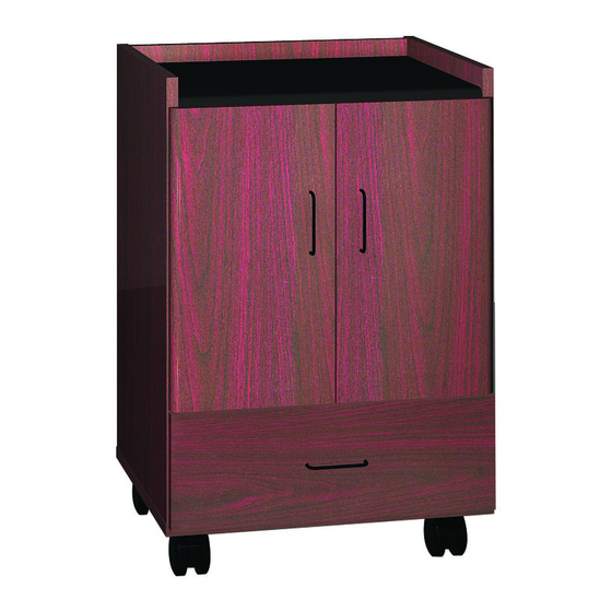
CB1
COFFEE BAR
I M P O R TA N T !
Assembly may require the assistance of
another person.
Before you begin assembly:
READ THE DIRECTIONS all the way through one
time. This will speed up the process and help you
understand the sequence of steps.
COUNT THE PARTS AND HARDWARE before
assembly. This ensures you have received all
necessary parts before you begin.
TOOLS: You may need a Phillips head screwdriver,
a medium slotted screwdriver or a plastic mallet. To
protect your new furniture from damage during
assembly, it is recommended to work on a
carpeted surface.
0512
In the event any parts are missing from
this package, send your name, address,
telephone number, and a description of
the missing part(s) to: PARTS, Box 1420,
Missoula, MT 59806 or call:
1-800-769-5693 or FAX 1-800-445-5281.
CAUTION: On assemblies requiring glue, make
sure the unit is assembled correctly before gluing.
Once this unit is assembled with glue, the
manufacturer will not be responsible for damaged
parts. Keep a damp cloth or sponge handy to wipe
off excess glue.
To care for this furniture, simply wipe with a cloth
dampened with glass cleaner containing ammonia-D.
Advertisement

Subscribe to Our Youtube Channel
Related Manuals for Ironwood CB1


Summary of Contents for Ironwood CB1
- Page 1 COFFEE BAR I M P O R TA N T ! In the event any parts are missing from Assembly may require the assistance of this package, send your name, address, another person. telephone number, and a description of Before you begin assembly: the missing part(s) to: PARTS, Box 1420, Missoula, MT 59806 or call: READ THE DIRECTIONS all the way through one...
-
Page 2: Parts Diagram
PARTS DIAGRAM Left Side 05850341 1 ea. Back 05850352 1 ea. Right Side 05850341 1 ea. Bottom 05850311 1 ea. 05850301 1 ea. Drawer Front 05850363 1 ea. Doors 05850373 2 ea. Shelf 05850311 1 ea. Drawer Sides 069270 2 ea. Drawer Bottom 191665 1 ea. - Page 3 HARDWARE Minifix Cam 909810 18 ea. Minifix Bolt 909834 18 ea. Wood Dowel 195000 16 ea. Hinge Plate 400201 4 ea. Plate Caster 402050 2 ea. Plate Caster 402051 2 ea. W/ Lock Lg. Panhead 988056 16 ea. Screws Hinge 400200 4 ea.
- Page 4 Washer Head 920200 2 ea. Confirmat 5x50 Screws 950100 8 ea. Screws Drawer/Door 200070 3 ea. Pulls 1-1/4” Panhead 4 ea. 901212 Screws 1-3/4” Quad 902215 2 ea. Washerhead Screws #6 x 3/4 Gold 8 ea. H2225 Flathead Screws Plastic Drawer 267100 2 ea.
- Page 5 Place the Back (D) on a clean, carpeted Place the Top (C) on a clean, carpeted surface as shown. Insert six Minifix Cams surface as shown. Insert four Minifix Cams (H1) into the Back where indicated with the (H1) into the Top where indicated with the arrows of the cams facing out.
- Page 6 Attach Hinge Plates (H4) to Left Side (A) and Right Side (B) using the attached screws into the pre-drilled holes as shown. IMPORTANT! The large hole and slots must be oriented to the rear edge of the Hinge Plates as shown. Screw plastic slides in place with four Flathead Screws (H17) each.
- Page 7 Position the Top (C) onto the Left Side (A) as shown. Turn the arrows of the two indicated Minifix Cams (H1) in the Top ROUNDED clockwise to secure in place. FRONT EDGE Position the Shelf (G) onto the unit as shown.
- Page 8 Insert Bolts and Dowels into Bottom (E) Position and secure. # 10 Attach four Plate casters (H5 and H6) to the Bottom Panel (E) using the Panhead Screws in the pre-drilled holes as shown. (H7) Using a Plastic Mallet, insert the Hinges (H9) into both Doors (I). # 11 Remove backings and press Square Black Bumpers (H10) onto the opposite corners of Doors where indicated.
- Page 9 Turn the unit upright. To attach the # 12 Doors (I) to the unit, slide the slots of the Hinges (H9) onto the Hinge Plates (H4) until the release buttons SLOT click into place. RELEASE BUTTON UP & # 13 Adjust Doors (I) to open and close easily by DOWN loosening hinge screws and repositioning...
- Page 10 # 15 Spread a thin layer of glue on both end edges and one side edge of Drawer Bottom (D5). Slide Drawer Bottom into the grooves of the Drawer End Panels (D2) until seated into the Drawer Side (D1) groove as shown. # 16 Apply glue to exposed edges of the Drawer Bottom (D5) and End Panels (D2).
- Page 11 # 17 Attach Drawer Front (J) to the Drawer unit using two Washer Head Screws (H13) in the outside holes as shown. # 18 With the drawer in place, check to insure that the Drawer Front (J) is aligned level and with equal spacing at the edges.
- Page 12 # 19 When adjusted, attach a Handle (H14) to Attach a Handle (H14) to each Door (I) using the Drawer Front (J) using two 1-3/4” two 1-1/4” Panhead Screws (H15) as shown. Washerhead Screws (H16) as shown. Your Coffee Bar is now fully assembled and ready for use.
Need help?
Do you have a question about the CB1 and is the answer not in the manual?
Questions and answers