Table of Contents
Advertisement
Quick Links
Advertisement
Table of Contents

Related Manuals for Ridder VitaLite-E


Summary of Contents for Ridder VitaLite-E
- Page 1 SV 8.0 24/03/2020 96000006 Installation and User Manual VitaLite-E and C...
- Page 2 B.V. This document may not be copied or made public by means of print, photocopy, digital copy or any other process, without the prior written permission of Ridder Growing Solutions B.V. Publication date: 24/03/2020 11:32 Manual version number: 030 Item code:...
-
Page 3: Table Of Contents
Contents 1 Introduction to this manual 1.1 Introduction 1.2 Aims 1.3 Target groups 1.4 Symbols and annotations 1.5 Documentation overview 2 Product information 2.1 Schematic representation of the unit 2.2 Basic configuration 2.3 Description of I/O modules 2.3.1 Replacing I/O modules 2.3.2 Removing I/O modules 2.4 Intended use 2.5 Other product characteristics... - Page 4 4.8.1 Display board of the control panel 4.8.2 Connecting Synopta 5 Commissioning 5.1 Control panel 5.1.1 Reading out and setting variables 5.1.2 Alarms 5.2 Commissioning 5.2.1 Log in at dealer level 5.2.2 Check settings 5.2.3 Set start conditions 5.3 Testing the unit 5.3.1 Manually start disinfection 5.3.2 Manually start cleaning quartz tubes 5.3.3 Manually start filter flushing...
- Page 5 8.6 Unit 8.6.1 Control mode 8.6.2 Safeguards 8.6.3 Unit characteristics 8.7 Drain group settings 8.7.1 Warming up UV lamps 8.7.2 Start conditions 8.7.3 Period 8.7.4 Control 8.7.5 Drain groups / Safeguards 8.7.6 Drain groups / Drain group characteristics 8.7.7 Drain groups / Control characteristics 8.8 Cleaning quartz tubes settings 8.8.1 Cleaning quartz tubes / Control 8.8.2 Cleaning quartz tubes / Safeguards...
-
Page 6: Introduction To This Manual
VitaLite-E and C the users of the VitaLite-E and C In general, installation will be carried out by the dealer of the VitaLite-E and C. This manual uses the term ‘dealer’ to mean both the dealer and the installer. -
Page 7: Documentation Overview
A window is indicated as follows: the Log On window. Documentation overview This manual is part of a set of manuals included with the unit that was purchased. Provided with every VitaLite-E and C model Manual (this manual) OEM manuals (original manuals of components such as pumps) -
Page 8: Product Information
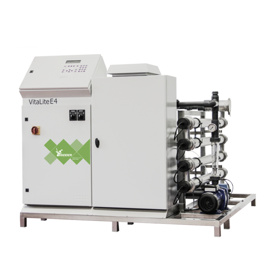
VitaLite Product information This section describes the components and the functioning of the VitaLite-E and C. Schematic representation of the unit Each unit is built according to the principles in the diagram below. There may be some minor differences depending on the unit that you are installing. -
Page 9: Basic Configuration
Sand filter with valves Description of I/O modules The VitaLite-E and C uses I/O modules from the Compactima series. A Compactima module is a network node suitable for connecting peripheral equipment. You mount the modules in the main cabinet or an expansion cabinet by simply clicking them into... -
Page 10: Replacing I/O Modules
VitaLite For a detailed technical description of the modules, please consult the insert provided. Figure 2-2: A Compactima I/O module General characteristics of the Compactima modules: Technical data of all types Width x height x depth 107.6 x 89.7 x 62.2 mm Weight 0.191 kg Mounting technique... -
Page 11: Removing I/O Modules
7 below. 6. Repeat this procedure for the other modules. 7. Next, shut down the VitaLite-E and C in the correct manner. To do this, press and hold down push button 2 on the display board for three seconds. Wait until LED 2 on the display board lights up orange. -
Page 12: Intended Use
7. Switch the controller back on. Intended use The Ridder Growing Solutions VitaLite-E and C series is designed to disinfect drain water with the aid of UV light in a horticultural environment. The Ridder Growing Solutions VitaLite-E and C series and all its components have been developed specifically for a horticultural environment. -
Page 13: Type Plate
The corresponding certificate can be found in the documentation included with the unit. A control cabinet that passes our quality inspection is provided with the label below on the inside of the cabinet. Please contact Ridder Growing Solutions if this label is missing. -
Page 14: Components, Stickers And Names
VitaLite Inspected by: 2 Name: xxxxxxxx 3 Date DD/MM/JJ 4 Sign xxxxxxxxx 1 Title and logo 3 Date inspected 2 Inspector name 4 Inspector signature 2.5.3 Components, stickers and names The main components of the unit are provided with an identification sticker. The table below describes the meaning of each sticker. - Page 15 VitaLite SDi1..4 Disinfected Disinfected Tanks for storing the disinfected water. water tanks storage 1,2,3,4 1,2,3,4 SDr1..4 Drain Drain Tanks for storing drain water. water tanks storage 1.2.3.4 1,2,3,4 Fresh Fresh Tanks for storing fresh water. water water tank storage Filters FSa1..3 Sand Sand Filter for removing suspended solids from the...
-
Page 16: Certificates And Declarations
2.5.4 Certificates and declarations The design and manufacture of the Ridder Growing Solutions VitaLite-E and C and components supplied with it corresponds with the following standards: CE directives 2014 / 30 / EU Electromagnetic Compatibility 2014 / 35 / EU Low Voltage Directive... -
Page 17: Packaging, Storage And Shipment
VitaLite Packaging, storage and shipment 2.6.1 Packaging The VitaLite-E and C is shipped in one or more large crates and includes a number of boxes containing separate components. 2.6.2 Transport To prevent damage during transport, certain components are shipped separately. - Page 18 VitaLite Dispose of the containers in accordance with the applicable regulations in your country. Consult the safety data sheets provided by the producers of the substances or equipment you are disposing of and follow the safety instructions specified. Also see the chapter "Safety precautions and requirements" on page 19.
-
Page 19: Safety Precautions And Requirements
VitaLite Safety precautions and requirements When installing, using or removing the unit, please observe the safety precautions and requirements listed below. See also: "Installation requirements" on page 22. General safety requirements This unit is subject to the following general safety and regulatory requirements. See also: "Installation requirements"... -
Page 20: Uv-C Radiation
After deactivation, the UV-C system and lamps will remain hot for a considerable time. Let the system cool down for at least 10 minutes. The stainless steel housing and the VitaLite-E and C's electronics must always be grounded (earthed). Wear suitable safety goggles or hood if you are working with an operating UV-C lamp to prevent damage to your retinas and skin. -
Page 21: Chemicals
In the event of an emergency: switch off the VitaLite immediately. The power switch is located on the VitaLite-E and C cabinet. Figure 3-1: The power switch Turn the power switch to the 0 (off) position to switch off the VitaLite-E and C. -
Page 22: Installation Procedure
The following requirements apply to installing the VitaLite-E and C on site: Make sure that the VitaLite-E and C is level. Install the VitaLite-E and C on a hard surface that is able to support its weight. Install the unit in a dry, dust-free location (1) Check the ambient temperature. - Page 23 VitaLite To prevent damage during transport, certain components are: not fastened tightly. If necessary, tighten the couplings. shipped separately. Make sure that these components are installed correctly. Figure 4-1: Illustrations showing installation requirements Location Check whether the unit has been positioned correctly, see "Installation requirements" on the previous page.
-
Page 24: Water Installation Requirements
VitaLite 4.1.3 Water installation requirements Please note the following installation requirements with regard to the water components: To prevent damage during transport, certain components are shipped separately. Make sure to install these components correctly. If an automatic filter is used, ensure that there is enough free space to open or remove the internal filter. -
Page 25: Installation Checklist
VitaLite When installing the sensors, please bear in mind the following: To ensure the best possible performance, the sensors should be placed in an open pipe slanted at the bottom. Secure the pipe to the water tank. Make sure that the pipe does not damage the tank lining. Place the sensors slightly above the bottom of the tank so sludge formation at the bottom will not affect their operation. - Page 26 VitaLite Done Step Section Check location and position "Location" on page 23. Connect the water components of the "Connecting water components unit (water installation)" on the facing page. Connect the electrical system "Connecting electrical components" on page 29. Connect the acid tank (partially filled "Connecting acid dosing with water) and then connect the acid components"...
-
Page 27: Connecting Water Components (Water Installation)
The unit is supplied with screw couplings. A dummy pipe is fastened to all connection points to protect the unit during transit. Remove this pipe before connecting the correct pipe. All units are built in metric sizes. Metric-to-imperial adapter sets are available from Ridder Growing Solutions. -
Page 28: Pre-Blending Control (Optional)
2. Remove the dummy pipes and connect the filters to the unit using the screw coupling. 3. Fill the filters with sand as directed. 4. Check the number of filters in the VitaLite-E and C software and adjust this number as necessary. 5. Connect the valves to the electrical connection (screw terminal). -
Page 29: Connecting Electrical Components
To connect the electrical components, complete the following steps: 1. Measure the supply voltage and make sure that it matches the design specifications of the unit. Contact Ridder Growing Solutions should this not be the case. 2. Connect the supply voltage according to the included electrical circuit diagram. - Page 30 Nitric acid is recommended as a cleaning agent because many greenhouse operations use it as a fertilizer. If you wish to use a different type of acid than nitric acid, please consult with Ridder Growing Solutions first to ensure that the acid is suitable for cleaning the unit.
-
Page 31: Ph Calibration
A pH sensor must not be allowed to dry out. The pH sensor is kept moist during transport and storage with a protective cap containing water. Remove this cap before use and place the sensor back into it if the VitaLite-E and C is not in use for an extended period. -
Page 32: Installing Quartz Tubes And Lamps
VitaLite 7. Place the EC sensor in calibration solution EC 5. Press E. 8. Wait until the display indicates that the measuring time of 60 seconds has elapsed. 9. Press E to save the calibration values, or ESC to abort the calibration process. 10. - Page 33 VitaLite Figure 4-7: Exploded view of UV reactors with 44-mm and 55-mm diameters Item no. Item no. Description Ø44 mm Ø55 mm 85041500 85041500 Connection cable for lamp UL / CSA Cable gland with strain relief 97910071 97910071 Reactor cap (black) for quartz tube 97910062 97910061 Reactor cap (black) for quartz tube 97910020 97910030 Black pressure bush for quartz tube 98294440 98295540 Viton O-ring 43x4 for quartz tube 44...
- Page 34 VitaLite The reactor plug and the plug must be tightened with a special tightening tool. The tightening tool consists of a torque wrench adjusted to 20 Nm, with a special plate. Figure 4-8: Tightening tool and torque wrench To install a quartz tube, complete the following steps: 1.
-
Page 35: Quartz Tube Breakages
VitaLite 11. Push the quartz tube further into the UV reactor until the rings are just inside the reactor. 12. Partially screw the reactor plug onto the UV reactor. 13. Make sure that the quartz tube is lying against the reactor plug. 14. -
Page 36: Pressurizing The Unit
VitaLite 4.7.3 Pressurizing the unit Before installing the UV-C lamps, make sure that the unit is not leaking. Figure 4-11: Pressurizing the unit Description Manual drain water return valve, adjust to capacity Motorized drain water return valve Air bleed valve Manual drain water disinfected valve. -
Page 37: Installing Uv-C Lamps
VitaLite bars). 7. Remedy any leaky couplings or other leaks. The unit will automatically vent air through the air bleed valve. It is normal for some water to run out of the tube attached to the air bleed valve. 4.7.4 Installing UV-C lamps Once you have made sure that the unit is not leaking, you can install the lamps. -
Page 38: Other Installation Work
Repeat this procedure for all UV-C lamps. Other installation work These sections describe how to install other equipment or software, for example how to connect the VitaLite-E and C to the Synopta user interface software (PC). 4.8.1 Display board of the control panel On the inside of the control panel door, you will find the display circuit board (or display board for short). - Page 39 New start: A 'new start' restarts the controller and erases all settings in the process. Press and hold down the push button 1 while the VitaLite-E and C is starting up to initiate a new start. Wait until LED 1 lights up green.
-
Page 40: Connecting Synopta
LED 4 Red: Software alarm Flash card Flash card for making backups Ethernet Ethernet port for connecting the VitaLite-E and C to the port Synopta Server 4.8.2 Connecting Synopta If the user will also be operating the unit with the Synopta PC software, connect the Ethernet cable to the Ethernet port on the circuit board. -
Page 41: Commissioning
The VitaLite-E and C is controlled by the process control software. The process control software consists of a series of setting and readout options that allow you to operate the unit. - Page 42 VitaLite Button Description Decimal point button This button allows you to enter decimal points. Back/Erase button Used for navigation and to erase a value Allows you to abort entering a value Allows you to return to the previous menu Enter button This button allows you to select and adjust settings.
-
Page 43: Reading Out And Setting Variables
To suppress an alarm message, press the Erase button. The alarm will only be cancelled once the VitaLite-E and C has stopped its current operation. After resolving the error situation, you will need to restart a... -
Page 44: Commissioning
VitaLite Commissioning This section describes the settings that need to be checked or configured in order to commission the unit. For a list of the all the VitaLite-E and C settings, see: "Appendix A: Control overview" on page 59. 5.2.1 Log in at dealer level To log in at dealer level, proceed as follows: On the display, set <M>... - Page 45 VitaLite Activate the VitaLite-E and C manually and check the VitaLite-E and C for the following points: Are all the valves working correctly during the warm-up phase, disinfection and post-flushing? Is the pump running? Is the flow rate sufficient? Have the lamps switched on? Is the measured radiation level sufficient? Check the pH value and, if present, the EC value.
-
Page 46: Manually Start Cleaning Quartz Tubes
Manually start cleaning quartz tubes M Settings / Cleaning quartz tubes / Control / Manual control Activate the VitaLite-E and C manually and check the following points: Are all the valves working correctly? Is the pump running? Is the flow rate sufficient? Check the pH value during cleaning and post-flushing. -
Page 47: Manually Start Filter Flushing
Manually start filter flushing M Settings / Filter flushing / Control / Manual control Each filter is flushed individually. Activate the VitaLite-E and C manually and check the VitaLite-E and C for the following points: Are all the valves working correctly? -
Page 48: Quality Control
The transmission value T10 in [%] is the quantity of UV-C radiation that can penetrate a column of 10 mm of water. If the measured T10 value is lower than the value for which the VitaLite-E and C was designed, it will affect the performance of the unit. - Page 49 VitaLite Make sure that the VitaLite-E and C disinfection process has been running for at least ten minutes before taking a sample. Sampling method Start with the upper sampling tap (disinfected water). Sterilize the sampling tap with alcohol or burn the tap clean with a burner.
-
Page 50: Operation
VitaLite Operation As soon as the dealer has prepared the VitaLite-E and C for use, you can operate the VitaLite-E and C. This section first explains how to operate the power switch, the system pump and the dosing pump. After that, you will find instructions on how to operate the VitaLite-E and C. -
Page 51: Disinfection
The disinfection process consists of several sub-processes: warming up, active and post-flushing. Each of these sub-processes is described separately. The VitaLite-E and C can control multiple supply and storage tanks. These are called 'drain water tanks' and 'disinfected water tanks' respectively, or 'drain tanks' and 'disinfected tanks' for short (due to the limited space on the unit's display). -
Page 52: Warming Up Uv Lamps
VitaLite Figure 6-2: Drain group consisting of drain tank A and disinfected tank 1 Drain groups are usually set once, see "Drain groups / Drain group characteristics" on page 80. More information on how to set the other start conditions and periods for each drain group can be found in section "Drain group settings"... -
Page 53: Disinfection Active
During the disinfection process, water is pumped through the filters and past the UV lamps, and is finally collected in the disinfected tank. If the VitaLite-E and C is fitted with a mixing valve, the blending ratio between drain water and clean water can be controlled during the disinfection process. -
Page 54: Filter Flushing
VitaLite Figure 6-5: Post-flushing See also: "Control" on page 76. Filter flushing Dirt that has settled in the filter is removed by back-flushing the filter. The back- flushing process can be started manually, either by activating a setting in the software or by pressing the start button on the control panel. See also: "Filter flushing / Control"... -
Page 55: Cleaning Quartz Tubes
VitaLite Flushing can be stopped manually, either by activating a setting in the software or by pressing the stop button on the control panel. Filter flushing will stop automatically once the preset flush time has elapsed or the preset number of litres have been flushed. -
Page 56: Post-Flushing After Cleaning Quartz Tubes
VitaLite 6.5.2 Post-flushing after cleaning quartz tubes Once the acid has been circulated sufficiently, it is flushed from the quartz tubes. Depending on the preselected setting, the quartz tubes are flushed with water either from the drain tank or from the fresh water tank. You can also select whether the flush water should either be discharged from the system (as wastewater) or fed back into the drain tank. -
Page 57: Maintenance And Quality Control
VitaLite Maintenance and quality control To ensure that the VitaLite-E and C continues to operate at peak efficiency, the VitaLite-E and C must be inspected and maintained on a regular basis. The following sections outline the necessary maintenance procedures for the VitaLite-E and C. -
Page 58: Yearly Maintenance
VitaLite Yearly maintenance Certain maintenance tasks should be performed on the VitaLite-E and C at least once a year to ensure that it continues to operate smoothly. That is why Ridder Growing Solutions recommends investing in a Ridder Growing Solutions maintenance contract. -
Page 59: Appendix A: Control Overview
VitaLite Appendix A: Control overview The following sections provide a complete overview of all the unit's settings. A description of the settings has been included where necessary. Due to the limited space on the unit's display, the names of certain settings have been abbreviated. -
Page 60: System Settings
VitaLite <M> Settings / General Response to restart Pause: When power returns after a power failure, the group that was active before the power failure will be paused. Also, the alarm message 'Paused after restart’ will be generated. Continue: When power returns after a power failure, the interrupted processes will continue. -
Page 61: System Configuration
Solutions. Activation code correct This indicates whether the entered activation code, obtained from Ridder Growing Solutions, is valid. Without valid activation codes, the system will continue to operate for 30 days. Once this period has elapsed, all control processes will be locked. -
Page 62: Identification
PIN code: The identification number issued by Ridder Growing Solutions. Level code: The access code issued by Ridder Growing Solutions. Depending on the code that was issued, a user can log in in Dealer or Configuration mode. 8.2.3 Protected settings <M>... - Page 63 VitaLite <M> Settings / General / System configuration / Protected settings Type of total flow sensor Here you select the type of flow sensor used: GF15: GF15 sensor with pulse signal (frequency) Arad: Arad meter with 4-20mA current signal. Type of drain flow sensor Here you select the type of flow sensor used: None: No sensor is present.
- Page 64 VitaLite <M> Settings / General / System configuration / Protected settings radiation sensor Yes: Activates a second radiation sensor for monitoring the radiation measurements of the control sensor. No: No second radiation sensor is present. T10 sensor Yes: Activates a T10 sensor. This sensor measures the UV transmission rate through a 10-mm layer of water.
-
Page 65: Communication
VitaLite <M> Settings / General / System configuration / Protected settings Type of ballast Contact: A ballast that is controlled with a contact. MB-ZED: A ballast that is controlled via modbus type ZED. MB-PBF: A ballast that is controlled via modbus type PBF. Communication <M>... -
Page 66: Network Settings
VitaLite <M> Settings / General / Communication / Synopta settings Reset config ID If the Synopta port is used by a different controller, then the port can be reset by switching this setting to Yes. 8.3.4 Network settings <M> Settings / General / Communication / Network Settings IP Address Subnet mask Update server active... -
Page 67: Control Outputs
VitaLite <M> Settings / General / I/O / Modules Remove module Firmware 0 Firmware 1 Firmware 2 8.4.2 Control outputs <M> Settings / General / I/O / Control outputs Name The name of the control output in question. Value Range Location Backup settings <M>... -
Page 68: Safeguards
VitaLite 8.6.2 Safeguards <M> Settings / Unit / Safeguards Ignore lamp group malfunction No: When the lamp group malfunction alarm contact is activated, then the following alarm will be generated: 'Lamp group malfunction'. Yes: As soon as this setting is set to Yes, a lamp group malfunction will be ignored for the duration of 60 hours. -
Page 69: Unit Characteristics
VitaLite <M> Settings / Unit / Safeguards Delay blending ratio alarm [hh:mm:ss] This sets the duration that the 'Measured blending ratio' must continuously remain below the 'Calculated blending ratio' minus the 'Blending ratio deviation', or above the 'Calculated blending ratio' plus the 'Blending ratio deviation', for an alarm message to be generated. - Page 70 VitaLite If using the red GF15 PVC pulse/litre counter, you can use the following table: K-factor 128,450 64,160 39,270 22,490 13,700 7,860 4,620 3,300 100 2,150 150 1,080 <M> Settings / Unit / Characteristics Number of drain groups in use Here you enter the number of drain groups that are in use.
- Page 71 VitaLite <M> Settings / Unit / Characteristics Max. radiation measurement [mW/cm2] Here you enter the radiation intensity that corresponds to a 20mA signal from the radiation sensor. Supply water transmission [%] Here you enter the transmission value of the supply water to be disinfected.
- Page 72 VitaLite <M> Settings / Unit / Characteristics Max. total flow [m3/h] Here you enter the flow rate at which the flow sensor will generate a 20mA signal. K-factor drain flow [p/l] See K-factor table at the start of this Here you enter the K-factor in pulses/litre as specified section.
-
Page 73: Drain Group Settings
VitaLite <M> Settings / Unit / Characteristics Node ID mon. radiation sensor Here you enter the node ID of this Modbus sensor. See the sensor housing for the node ID that you need to enter here. Drain group settings <M> Settings / Drain group Warming up UV lamps Start conditions Period... -
Page 74: Start Conditions
VitaLite 8.7.2 Start conditions <M> Settings / Drain groups / Start conditions Manual control (from Synopta) Start: Start disinfection for the selected drain group. If the unit is busy, then the start command will be queued. Pause: Pause disinfection for the drain group that is currently active. - Page 75 VitaLite <M> Settings / Drain groups / Start conditions Di tank vol. start disinf per. 1 - 4 [m3] disinfected In full: Drain tank volume for start disinfection in period 1 - tank must be 4. If the volume of water in the disinfected tank drops below sufficiently the value set here, then disinfection will start during the empty to...
-
Page 76: Period
VitaLite <M> Settings / Drain groups / Start conditions Drain tank vol. high priority [m3] If the water level in the drain tank rises above the volume of water set here, then the highest priority will apply for this drain group. As a result, this drain group will take precedence over all other available drain groups. -
Page 77: Drain Groups / Safeguards
VitaLite <M> Settings / Drain groups / Control Enable discharge No: The water flowing past the quartz tubes during the post- flush phase will be fed back to the drain tank. Yes: The water flowing past the quartz tubes during the post- flush phase will be discharged from the system as wastewater. - Page 78 VitaLite <M> Settings / Drain groups / Safeguards Minimum I min flow [l/min] If the calculated flow rate drops below the value set here, then the alarm message 'Calc. flow at I min too low' will be generated. This alarm will be generated once the time set for 'Delay I min flow alarm' has elapsed.
- Page 79 VitaLite <M> Settings / Drain groups / Safeguards Dose flow deviation [%] This sets the percentage by which the ‘Measured total flow’ may drop below the 'Calculated dose flow'. If the 'Measured total flow' drops any lower, then the alarm message 'Dose flow too low' will be generated.
-
Page 80: Drain Groups / Drain Group Characteristics
VitaLite 8.7.6 Drain groups / Drain group characteristics <M> Settings / Drain groups / Drain group characteristics Drain tank selection Select the desired drain Here you select the number of the drain tank which should tank for this supply the drain water of the drain group. group. - Page 81 VitaLite <M> Settings / Drain groups / Control characteristics Max. blending ratio increase [%] This sets the maximum percentage by which the 'Calculated blending ratio' may be raised as a result of EC control. EC P-factor The blending ratio can be influenced by the degree of difference between the measured EC and the EC setpoint.
-
Page 82: Cleaning Quartz Tubes Settings
VitaLite <M> Settings / Drain groups / Control characteristics Dose flow gain This sets the degree to which the disinfected (water) valve should open or close in order to achieve the calculated flow, should it differ from the measured flow. Control pulse = Calculated flow - Measured flow x Dose flow gain Max. -
Page 83: Cleaning Quartz Tubes / Control
VitaLite 8.8.1 Cleaning quartz tubes / Control <M> Settings / Cleaning quartz tubes / Control Manual control (from Synopta) Start: Start cleaning the quartz tubes. If the unit is busy, then the start command will be queued. Pause: Pause cleaning of the quartz tubes if currently in progress. - Page 84 VitaLite <M> Settings / Cleaning quartz tubes / Control Flush duration [hh:mm:ss] The value to be set here depends on the This sets the duration that the quartz tubes will be design capacity. flushed with drain water or fresh water once the Small volume: 3 cleaning process has been completed.
-
Page 85: Cleaning Quartz Tubes / Safeguards
VitaLite 8.8.2 Cleaning quartz tubes / Safeguards <M> Settings / Cleaning quartz tubes / Safeguards Minimum m for start cleaning [m This sets the amount of water (in cubic metres) that must have passed through the quartz tubes since the last time that the quartz tubes were cleaned, in order for the cleaning process to start. -
Page 86: Control Characteristics
VitaLite 8.8.3 Control characteristics <M> Settings / Clean quartz tubes / Control / Manual control pH non-adjustment zone This sets the non-adjustment zone above the 'Calculated pH’ value. If the 'Measured pH' remains within this zone during the cleaning of the quartz tubes, then the pH control value will not be adjusted. - Page 87 VitaLite <M> Settings / Filter flushing / Control Start time filter flushing [hh:mm:ss] 00:00:00 This allows you to set the time from which the filter may be flushed automatically. End time filter flushing [hh:mm:ss] 23:59:00 This allows you to set the time until which the filter may be flushed automatically.
-
Page 88: Filter Flushing / Safeguards
VitaLite 8.9.2 Filter flushing / Safeguards <M> Settings / Filter flushing / Safeguards Minimum m3 for start flushing [m3] This sets the amount of water (in cubic metres) that must pass through the filter in order for filter flushing to start. If the amount of water is lower than the value set here, then the alarm message 'Quantity disinfected too low' will be generated and the unit will be paused. -
Page 89: Drain Tanks
VitaLite Figure 8-1: Water tank schematic with corresponding measurements The following measurements are used for the water tanks: Size Description Height at maximum range of the sensor (20 mA). The sensor may have a higher range than the actual height of the tank. 100% Height of the tank. -
Page 90: Disinfected Tanks
VitaLite <M> Settings / Drain tank Height of maximum level [m] Here you enter the height of the water level (in metres) at which the maximum volume of water is measured in the drain tank. Maximum range of level sensor [m] 100% Here you enter the height of the water level (in metres) at which the maximum sensor level is measured in the drain... -
Page 91: Uv Lamps
VitaLite <M> Settings / Disinfected tank Maximum range of level sensor [m] 100% Here you enter the height of the water level (in metres) at which the maximum sensor level is measured in the disinfected tank. Level m = Minimum volume + (((Level percentage/100) * Maximum range of level sensor) –... -
Page 92: Appendix B: Notifications
Check the radiation sensors. Activation code invalid The activation code that you have entered is invalid. Please contact Ridder Growing Solutions. The system will continue to operate for no more than 30 days without a valid activation code. - Page 93 VitaLite Message The measured pH value is too high (disinfection) Check the relevant preset value and alarm threshold. Check whether the dosing pump is operating correctly. Check whether the pH sensor is dirty or needs replacing because it is too old. If necessary, recalibrate the sensor.
- Page 94 VitaLite Message Flow too low (disinfection) The following error has occurred during disinfection: Check the relevant preset value and alarm threshold. Check whether the pump is working. Check whether any of the pipes are clogged. Check whether the filter is clogged. Flow too low (cleaning quartz tubes) The following error has occurred while the quartz tubes were being cleaned: The measured flow rate is too high.
- Page 95 VitaLite Message Ballast error An error has occurred with one of the ballasts. Either the ballast is not functioning correctly or the lamp is faulty. Check the ballast. Check the error codes in the UV lamp readouts. External contact activated (disinfection) The following error has occurred during disinfection: The external contact is activated.
- Page 96 Module unreliable The module failed to initialize while the controller was starting up. Switch the controller off and back on. Please contact Ridder Growing Solutions An unknown error has occurred. Unknown alarm The cause of the generated alarm could not be determined.
- Page 97 VitaLite Message Quantity of water disinfected too low (filter flushing) The unit has failed to disinfect the required quantity of water due to a dirty (clogged) filter. Flush the filter. Paused after restart (disinfection) Either a power failure has occurred or a restart has been initiated within 30 minutes of another restart.
- Page 98 VitaLite Message Control pH too low (disinfection) Check the relevant preset value and alarm threshold. Check whether the dosing pump is operating correctly. Check whether the pH sensor is dirty or needs replacing because it is too old. If necessary, recalibrate the sensor. Control pH too low (cleaning quartz tubes) Check the relevant preset value and alarm threshold.
- Page 99 VitaLite Message Pump contact sensor alarm The system has either failed to receive measurement data from the sensor or the measurement value is outside of sensor range. Check the sensor and the sensor cable. Acid tank contact sensor alarm The system has either failed to receive measurement data from the sensor or the measurement value is outside of sensor range.
- Page 100 VitaLite Message Monitor pH sensor alarm The system has either failed to receive measurement data from the sensor or the measurement value is outside of sensor range. Check the sensor and the sensor cable. Control pH sensor alarm The system has either failed to receive measurement data from the sensor or the measurement value is outside of sensor range.
- Page 101 VitaLite Message I/O module fault A malfunction with one or more of the modules has occurred. Check the system. Radiation too low The measured radiation level is too low. Check the radiation sensors. Check whether the water is too dirty. Radiation dose too low The measured radiation dose, which is related to the flow rate, is too low (applicable if disinfection is based on the radiation dose rather than the calibration curve).
- Page 102 VitaLite Message Test mode active The computer is in test mode for maintenance purposes. Module type not correct The type of module found does not match the type of module that was expected. The module has overloaded. The electric current protection of the outputs has been activated. Reset the module.
-
Page 103: Appendix C: Wiring List
VitaLite Appendix C: Wiring list This appendix contains the wiring lists for the unit. 10.1 Output / pH module, Module ID: 1, Inputs & 4- 20mA output Abbrev. Interface Terminal in Terminology Description Cable (Old) relay cabinet Control pH sensor direct on sensor High transp. -
Page 104: Output / Ph Module, Module Id: 1, Outputs
VitaLite 10.2 Output / pH module, Module ID: 1, Outputs Abbrev. Interface Terminal Terminology Description Cable (Old) relay in cabinet Software alarm #182 MY2, 28, 29, 30 24Vdc Pre-blending valve #202a RP10#1 153, (173) Open (KM) transp. (09) Pre-blending valve #202a RP10#1 163, (173) -
Page 105: Output / Input Module, Module Id: 2, Outputs
VitaLite 10.3 Output / Input module, Module ID: 2, Outputs Abbrev. Interface Terminal in Terminology Description Cable (Old) relay cabinet Supply valve 1 VSu1 #212b RP11#1 91, 101, (111) (KD1) black (01) Drain valve 1 VDr1 #212b RP11#1 92, 102, (112) (AD1) blue (02) -
Page 106: Output / Input Module, Module Id: 2, Inputs
VitaLite 10.4 Output / Input module, Module ID: 2, Inputs Signal Terminal in Terminology Description Abbrev. Cable type cabinet Radiation sensor IN Low, VP23XL / through IN Hi 0-4mA VP23XL on module System pump T2, AP2 MY4, 39, 49 alarm alarm contact grey 24VAC /... -
Page 107: Output / Input Module 5Th - 8Th Drain Group, Module Id: 3, Outputs
VitaLite Signal Terminal in Terminology Description Abbrev. Cable type cabinet Disinfected level LDi4 #316 4-20mA 208, 218, 228 sensors 4..1 orange 10.5 Output / Input module 5th - 8th drain group, Module ID: 3, Outputs Signal Terminal in Terminals Description Abbrev. -
Page 108: Output / Input Module 5Th - 8Th Drain Group, Module Id: 3, Inputs
VitaLite Signal Terminal in Terminals Description Abbrev. Cable type cabinet Drain valve 8 VDr8 RP11#2 (08) Disinfected valve 8 VDi8 RP10#2 Open (07) Disinfected valve 8 RP10#2 Close (08) 10.6 Output / Input module 5th - 8th drain group, Module ID: 3, Inputs Signal Terminal in Terminals... -
Page 109: Ec Pre-Blending Module Id
VitaLite 10.7 EC Pre-Blending Module ID: 4 Signal Terminal in Terminals Description Abbrev. Cable cabinet type Control EC sensor sens direct on High brown(40) module Control EC sensor sens green direct on (41) module Control EC sensor sens PT1000 direct on Temp yellow(42) module...
Need help?
Do you have a question about the VitaLite-E and is the answer not in the manual?
Questions and answers