Table of Contents
Advertisement
Quick Links
Advertisement
Table of Contents

Related Manuals for Teac WX-7000


Summary of Contents for Teac WX-7000
- Page 1 D01190210J WX-7000 WIDE BAND DATA RECORDER Owner’s Manual...
-
Page 2: Table Of Contents
Index 1. Introduction ........................5 Control input and output ................. 25 Status input and output ................25 1-1. Disclaimers ....................... 5 Input and output circuit format ............... 25 1-2. Included accessories ..................5 Serial communication ................. 25 Connector ......................25 1-3. - Page 3 index 6-7-3. Monitored channel ................34 10-8. Synchronization status display .............. 45 6-8. Trigger indicators ....................35 11. AQ-VU synchronized recording ................ 46 6-9. Function buttons ..................... 35 11-1. Connections ...................... 46 When stopped ..................... 35 11-2. Turning the units on ..................46 Pressing SHIFT while stopped ..............
- Page 4 17. Options ..........................76 17-1. Remote control ....................76 17-2. Interface cards ....................76 18. Specifications ....................... 77 18-1. Recording unit (WX-7000) ..............77 Recording media ....................77 RDX ........................... 77 SDHC ........................77 Sampling frequencies and bands ............77 Number of channels that can be recorded simultaneously ..
-
Page 5: Introduction
1. Introduction Thank you for purchasing the WX-7000 WIDE BAND DATA RECORDER 1-2. Included accessories (“WX-7000”). Please read this document in its entirety before using the product to get the best performance and ensure safe and proper operation. If anything is missing or damaged, contact us. (For contact informa- tion, see the last page.) -
Page 6: Features
Gigabit Ethernet 1-5. System composition o WX Navi waveform display software included This system is composed of a WX-7000 recording unit and one or o TAFFmat data format used more AU-WXEPIO expansion units. o Easy-to-read 320x240 3.5-inch TFT color display... - Page 7 1. Introduction WX-7032 (32 input and output channels) WX-7128 (128 input and output channels) WX-7064 (64 input and output channels) o When multiple AU-WXEPIO expansion units are connected, chan- WX-7096 (96 input and output channels) nel numbering starts with channel 1 at the top left and ends with the last channel (32, 64, 96 or 128) at the bottom right.
-
Page 8: Recording Media
1. Introduction 1-6. Recording media 1-7. TAFFmat format Open the drive cover of the WX-7000 unit to access the RDX docking 1-7-1. Type of files station and SDHC card slot. The WX-7000 makes a binary-format data file and ASCII-format header file each time recording stops or pauses. -
Page 9: Directory Structure Of Media
Bbbbb001.hdr WXDAT 1/6000 This directory is made automatically when the medium is ch14 formatted. When the medium is inserted in an WX-7000, this ch15 directory is made automatically if it does not already exist. ch16 TEST0001 Name of the directory entered in DIRECTORY, which is in the dialog box displayed by choosing FILE and then RECORDING 1-7-5. -
Page 10: Header File
Example of header file DATASET TEST0001 VERSION 1 SERIES CH1_WX7K_PAAMP,CH2_WX7K_PAAMP,CH3_WX7K_PAAMP,CH4_WX7K_PAAMP,CH5_WX7K_PAAMP,CH6_WX7K_PAAMP,CH7_WX7K_ PAAMP,CH8_WX7K_PAAMP DATE 01-01-2013 TIME 12:00:00.00 RATE 192000 VERT_UNITS V,V,V,V,V,V,V,V HORZ_UNITS Sec COMMENT WX-7000 NUM_SERIES 8 STORAGE_MODE INTERLACED FILE_TYPE INTEGER SLOPE 8.000000e-005,8.000000e-005,8.000000e-005,8.000000e-005,8.000000e-005, 8.000000e-005,8.000000e-005,8.000000e-005 X_OFFSET -1.0 Y_OFFSET 0.000000e+000,0.000000e+000,0.000000e+000,0.000000e+000,0.000000e+000, 0.000000e+000,0.000000e+000,0.000000e+000 NUM_SAMPS 11904000 DATA DEVICE WX-7000... -
Page 11: Explanations Of Header File
Firmware version of the WX-7000 sub, Firmware version of the LCD, DSP and FPGA version of the WX-7000 amplifier o In media recording, the WX-7000 attaches the following information after DEVICE when the data are automatically divided into segments of maximum size(4GB). -
Page 12: Important Safety Precautions
DISCLAIMER TEAC disclaims all warranty, either expressed or implied, with respect to this product and the accompanying written materials. In no event shall TEAC be liable for any damages whatsoever (including, without limitation, damages for loss of business profits, business interruption, loss of... -
Page 13: Connections
Connect the included AC adaptor to the DC IN on the WX-7000. 3-1-3. WX-7064 Included AC adaptor Connection cable Connect one included AC adaptor to the DC IN on the WX-7000 and the second included AC adaptor to the DC IN on the third AU-WXEPIO unit from the top. -
Page 14: Wx-7096
Connection cable Connect one included AC adaptor to the DC IN on the WX-7000, the second adaptor to the DC IN on the 3rd AU-WXEPIO unit from the top, the third adaptor to the 5th unit and the fourth adaptor to the 7th unit. -
Page 15: Connecting An Uninteruptible Power Supply (Ups)
For complete protection against power outages, use an uninterrupt- ible power supply (UPS) for the external power source. Have the UPS send a power outage contact signal to the WX-7000 so that it will conduct recording completion procedures. Power the WX-7000 through its AC adaptor from a power output from the UPS. -
Page 16: Connecting With Computers And Oscilloscopes
A Transducer Electronic Data Sheet (TEDS) is a standard format defined in IEEE 1451.4 for recording information specific to a measurement sen- sor that is stored within the sensor itself. By connecting a TEDS sensor with a TEDS-compatible WX-7000, sensor calibration is made unnecessary, reducing the time required for measurement preparations. -
Page 17: Connecting Sensors
3. Connections 3-5. Connecting sensors Oscilloscope or other device Microphone Earphone Input setting: PA Input setting: AC Input setting: DC Example: Piezoelectric accelerometer Voltage output type with built-in preamp 724ZT triaxial TEDS-compliant ICP Ampli er for piezoelectric TEDS-compliant strain/DC ampli er accelerometers SA-570ST SA-611... -
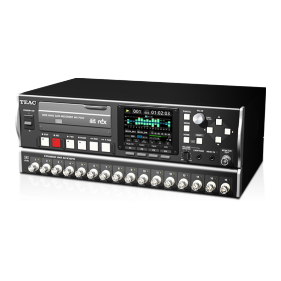
Page 18: Names And Functions Of Parts
4. Names and functions of parts 4-1. Front panels WX-7000 recording unit o Drive cover open AU-WXEPIO expansion unit... - Page 19 4. Names and functions of parts RDX indicator STANDBY/ON (¤) switch This shows the RDX status as follows. Press to turn the power on or put the unit into standby. Press the switch up to turn the power on. Press it down to put Indicator Meaning Explanation...
- Page 20 4. Names and functions of parts MONITOR OUT connector Input connectors This can be used to output a monitor signal, which can be the Use these to input measurement signals. input signal of any channel or the voice memos. SDHC card slot Insert SDHC cards here.
-
Page 21: Side Panels
AU-WXEPIO Joint bars Built-in speaker The WX-7000 and AU-WXEPIO units are physically connected by This outputs voice memos. four joint bars. The lengths of the joint bars differ for the WX-7016, o When an earphone is connected to the earphone jack, no WX-7032, WX-7064, WX-7096 and WX-7128 models. -
Page 22: Rear Panels
4. Names and functions of parts 4-3. Rear panels WX-7000 recording unit K L M AU-WXEPIO expansion unit OPTION-1 slot EXPANSION OUT connector This slot is for an option card with a height of 20.5 mm. Connect this to the EXPANSION IN connector of the AU-WXEPIO below it using a connection cable. - Page 23 EXPANSION OUT connector Connect this to the EXPANSION IN connector of the AU-WXEPIO below it using a connection cable. EXPANSION IN connector Connect this to the EXPANSION OUT connector of the WX-7000 or AU-WXEPIO unit above it using a connection cable.
-
Page 24: Connector Specifications
5. Connector specifications Pin assignments 5-1. DIGITAL CONTROL input connector Signal Function Ground RESERVED Reserved Function RESERVED Reserved Ground Use to control recording and playback with contact signals and to connect an optional remote control unit. RESERVED Reserved RESERVED Reserved Contact input Ground Ground... -
Page 25: Pin Assignments
5. Connector specifications Pin assignments 5-2. SYNC IN and SYNC OUT connectors Signal Function Function Power supply 0 V SYNCFS+ FS clock + Use these input and output connectors for synchronized recording SYNCFS- FS clock - with two systems. Do not connect anything when not conducting Power supply 0 V synchronized recording. -
Page 26: Aq-Vu Synchronized Recording Connector
5. Connector specifications 5-3. AQ-VU synchronized recording 5-4. EXT TRIGGER IN connector connector Function Function Use to input external trigger contact signals to start and stop recording. Use to control starting and stopping of AQ-VU recording, as well as to synchronize the time. Changing from H to L starts recording. -
Page 27: Dc In Power Connector
5. Connector specifications 5-5. DC IN power connector 5-6. UPS SIGNAL IN contact input connector Function Function Input a voltage between 11 V and 30 V. If a power outage occurs when using this system with a UPS power supply and a UPS power outage detection contact signal is input Connector here, recording closing procedures will be conducted to stop record- ing . -
Page 28: Basic Operation
When purchased new, RDX cartridges are NTFS formatted. Format cartridges with the WX-7000 before using them with this system. o When not using a cartridge store it in a protective case. o Do not stack RDX cartridges. -
Page 29: Protection Switch
6. Basic operation 6-1-2. Protection switch Ejecting RDX cartridges Press the EJECT button. After the RDX cartridge is ejected from the docking station, pull it out directly. protection switch If an RDX cartridge cannot be ejected If an RDX cartridge cannot be ejected, stop the power supply to the unit and confirm that the EJECT button indicator is unlit. -
Page 30: Sdhc Cards
Insert SDHC cards when the unit is in standby mode (power off ). Open the drive cover. Before turning the power off for the recording unit (WX-7000), eject the RDX cartridge and SDHC card. If the power is turned off while data is being written, data recorded on that medium might become Push the SDHC card all the way in. -
Page 31: Status Changes
6. Basic operation 6-5. Status changes 6-5-1. Explanation of status change diagram entry Entries appear on the status change diagram in the following manner. Stopped Status Waiting for button input or setting Possible operations [ 0 REC] Status change (by button or menu) 6-5-2. -
Page 32: Home Screen
6. Basic operation 6-6. Home Screen Recording unit status indicator Data display This icon shows the current status of the recording unit. These bar meters show the levels of the channels. The meanings of the icons are as follows. Press the F1 (Peak Clear) button to reset the peak hold display. Stopped Playback ready Playing back... - Page 33 Number of recording channels recording unit. When playing back or ready for playback, this shows the WX-7000 and AU-WXEPIO fans ON or OFF time the recording was made. At all other times, this shows the current setting of the MEMO unit.
-
Page 34: Data Display
6. Basic operation 6-7-2. Peak indicators 6-7. Data display Peak indicators are shown when ready to record, when recording and when playing back. When recording or ready to record, bar meters show the input level of each channel. Example Display channels Peak Peak Monitor channel... -
Page 35: Trigger Indicators
6. Basic operation 6-8. Trigger indicators 6-9. Function buttons The assignments of the Function (F1, F2, F3, F4) buttons are shown at the bottom of the screen. The assignments of the Function buttons change according to the status of the recording unit as follows. Stop trigger When stopped Start trigger... -
Page 36: Pressing Shift While Recording
6. Basic operation Pressing SHIFT while recording When playing back F1 button: (No indication) F1 button: Peak Clear No function. Resets the bar meter peak hold indicators. F2 button: Input Amp confirmation F2 button: (No indication) Check the settings on the INPUT SETTING screen. No function F3 button: Output Amp confirmation... -
Page 37: Recording Media Information
FILE screen. o RDX cartridges in NTFS format (immediately after purchase, for example) cannot be used as is with this system. Format them with the WX-7000 before use. o SDHC cards smaller than 2 GB are not supported. -
Page 38: Changing Settings From The Home Screen
7. Changing settings from the Home Screen You can change settings on the menu screens, but you can also Turn the VALUE knob to change the setting change settings that are used frequently on the Home Screen. value. 7-1. Screen operations You can also use the up and down (5, b) buttons to change the setting value. -
Page 39: Recording
8. Recording 8-1. Order of procedures 8-4. Setting triggers In addition to manually starting and stopping recording, you can Set the recording conditions also set the system to start and stop recording using triggers and intervals. For details about how to make settings, see page 67. Set the recording destination 8-4-1. -
Page 40: Interval Recording
Recording time Recording time Data recorded by WX-7000 series units uses the FAT32 file system for- mat. The maximum size of files recorded in this format is 4 GB. When recording for a long time, new files will be created automati- cally every 4 GB. -
Page 41: Playback
9. Playback 9-1. Order of procedures 9-5. Searching by event Set the playback conditions When ready for playback, select the event number (EVENT), and use the VALUE knob to search by event number. Then, press the VALUE Select the playback file knob to start playback from the position of that event number. -
Page 42: Searching By Time
10. Synchronization function 9. Playback 9-7. Searching by time 10-1. Connections When ready for playback, select the date and time (TIME), and search Master unit for the desired date and time. Then, press the VALUE knob to start playback from the position of that date and time. Synchronization cable Slave unit o Use a synchronization cable to connect the master unit SYNC OUT to... -
Page 43: Synchronized Recording Settings
10. Synchronization function 10-3. Synchronized recording settings 10-5. Confirming synchronization connections If you set the master unit SAMPLING FREQ, AD BIT and recording destination, they will also be set for the slave unit automatically. In the master unit SYSTEM menu, select SYNCHRO SETTING, and These cannot be changed from the slave unit. -
Page 44: Checking Connections
10. Synchronization function o The slave unit does not have a CONNECT CHECK option. 10-6. Checking connections Confirm that the master and slave units are connected correctly. Select CONNECT CHECK on the master unit and press the VALUE knob. Connection status Connection status If the connection check conducted on the master unit completes successfully, the connection status of the slave unit will be shown as... -
Page 45: Adjusting The Time
10. Synchronization function 10-7. Adjusting the time 10-8. Synchronization status display Select ADJUST TIME on the master unit, and press the VALUE knob. When synchronization connection is in use, the synchronization sta- tus is shown on the HOME screen. Synchronization status The time is shown on the master unit. -
Page 46: Aq-Vu Synchronized Recording
11. AQ-VU synchronized recording 11-1. Connections 11-3. Settings Set the AQ-VU for recording start and stop control, including the Main unit clocks of both units. o Synchronized playback of the main unit and the AQ-VU is not possible. o To synchronize the AQ-VU, set AQ-VU SYNCHRO to ON on the AQ-VU SETTING screen. -
Page 47: Aq-Vu Synchronized Connection Settings
11. AQ-VU synchronized recording 11-4. AQ-VU synchronized connec- 11-5. Setting the time tion settings Select ADJUST TIME and press the VALUE knob to show the time set- ting of the main unit. From the main unit SYSTEM menu, select AQ-VU SETTING and press o Before setting the time, set AQ-VU SYNCHRO to ON. -
Page 48: Settings
12. Settings You can change settings on the menu screens, but you can also Press the VALUE knob. change settings that are used frequently on the Home Screen. 12-1. Basic operation Follow these procedures to change settings using the menu screens. If you select an item that has its current value shown to its right, Press the MENU button on the front panel to a list of values opens and you can change the selected item’s... -
Page 49: Selecting Values From Setting Options
12. Settings After you finish making settings, press the 12-2. Selecting values from setting HOME button on the front panel to return to options the Home Screen. The current setting value of a menu item is shown to its right. To set a different value for a parameter such as the sampling fre- quency, press the VALUE knob to show a list of options to the right of the current setting value. -
Page 50: Inputting Numbers As Setting Values
12. Settings 12-3. Inputting numbers as setting 12-4. Inputting characters as setting values values To input a numerical value within a certain range for a param- To input characters as a setting value, such as a CHANNEL NAME, eter such as the OUTPUT SETTING, press the VALUE knob to enable press the VALUE knob to open the character input screen. -
Page 51: Opening Submenu Screens
12. Settings 12-5. Opening submenu screens 12-6. Menu screen item list HOME Sampling series (SERIES) The menu screen has a multilevel structure. Select a menu item Sampling frequency (SAMPLE) with an arrow (>) to its right and press the VALUE knob to open its Analog-digital conversion bit depth (AD) submenu screen. - Page 52 12. Settings SYSTEM Sampling series (SAMPLING SERIES) Sampling frequency (SAMPLING FREQ.) Number of active channels (ACTIVE CHANNEL) Analog-digital conversion bit depth (AD BIT) Voice memo activation (VOICE MEMO) Monitoring output channel (MONITOR CHANNEL) Monitoring output range (MONITOR RANGE) Input settings (INPUT SETTING) Input range (INPUT RANGE) Coupling (COUPLING) :...
- Page 53 12. Settings FILE Recording le (RECORDING FILE) Media selection (DEVICE) Directory name (DIRECTORY) File name (FILE) Comment (COMMENT) Playback le (FILE OPEN) Media selection Directory name File name File information Playback mode Delete les (FILE DELETE) Format the media (FORMAT) Trigger mode (MODE) No triggers (NONE) Trigger recording (TRIGGER)
- Page 54 12. Settings MISC Set data shown on Home Screen (DISPLAY DATA) Set number of channels shown with bar meters (DISPLAY CH) Setting saving, loading and initialization (PARAMETER) Speaker output setting (SPEAKER) Fan activation (FAN) Sampling notation setting (NOTATION) Language setting (LANGUAGE) Network settings (NETWORK) Date and time settings (TIMESET) Display adjustment (LCD)
-
Page 55: Setting Values List
UNIT 8qUNIT 8 DEVICE RDX, SD DIRECTORY (name) WX7K_DIR 8 ASCII characters maximum FILE (name) WX7K_ 5 ASCII characters maximum COMMENT WX-7000 64 ASCII characters maximum MODE (trigger) None None, trigger, interval DISPLAY DATA %, dB DISPLAY CHANNEL 16CH 16CH, 32CH... -
Page 56: System Menu
13. SYSTEM menu 13-1. INPUT SETTING From the SYSTEM menu, select the INPUT SETTING item and press the VALUE knob to open the INPUT SETTING screen. The first channel numbers are shown with their settings beneath them. Change the channel numbers shown with the F1 (PREV PAGE) and F4 (NEXT PAGE) buttons. -
Page 57: Individual Channel Settings
They do not affect the display, output signals or Press the F2 button to open a confirmation screen. recording data of the WX-7000. Selection Use the VALUE knob and the up, down, left and right (5, b, g, t) buttons to change the selection. -
Page 58: Sensor Voltage
13. SYSTEM menu 13-1-2. Sensor voltage 13-2. OUTPUT SETTING On the INPUT SETTING screen, press the F2 (Sens Volt) button to open the sensor voltage screen. In the SYSTEM menu, select OUTPUT SETTING and press the VALUE This screen shows the connected expansion unit numbers and their knob to open the OUTPUT SETTING screen. -
Page 59: Output Unit
13. SYSTEM menu 13-2-1. OUTPUT UNIT Setting example 1 When using a WX-7016 system to play back a 128-channel file On the OUTPUT SETTING screen, press the F2 (OutUnit Set) button recorded using a WX-7128 system, in order to play back data to open the OUTPUT UNIT screen. -
Page 60: Teds
13. SYSTEM menu 13-3-1. Loading TEDS data 13-3. TEDS If a TEDS sensor is connected after the power has already been turned on, the TEDS data will not appear on the screen automati- cally. Press the F3 button to reload TEDS data. The following screen appears while the TEDS data is being loaded. -
Page 61: Calibration
13. SYSTEM menu 13-4-2. Test signal output 13-4. Calibration Select TEST SIGNAL OUT, and push the VALUE knob. Current selection To change the test signal output, use the VALUE knob to select the Selection desired output. Use the VALUE knob and up and down (5, b) buttons to change the selection. -
Page 62: Synchronization Settings
14. FILE settings 13. SYSTEM menu 13-5. Synchronization settings See “10. Synchronization function” on page 42. 13-6. AQ-VU settings See “11. AQ-VU synchronized recording” on page 46. Current selection Media information Selection Use the VALUE knob and the up, down, left and right (5, b, g, t) buttons to change the selection. -
Page 63: Media Information
14. FILE settings 14-1. Media information 14-2. New file settings This screen shows information about the selected recording media. In the FILE menu, select RECORDING FILE and press the VALUE knob to open the RECORDING FILE screen. Current selected media Usage Current selection Selected media... -
Page 64: Directory
14. FILE settings 14-2-2. Directory 14-3. Opening files Select the directory where recording files are saved. In the FILE menu, select FILE OPEN and press the VALUE knob to open the FILE OPEN screen where you can play back files. Current selection Selection Select the media with the file that you want to open. -
Page 65: Selecting Directories
14. FILE settings 14-4. Selecting directories 14-5. Selecting files Total number of directories Total number of les Current directory Current directory Selected directory number Selected le number Current selection Current selection Select the directory with the file that you want to play back. On this screen, you can select a file for playback. -
Page 66: Deleting Files
14. FILE settings File Info. (F4 button) 14-7. Formatting media Show the following information for the selected file: Sampling frequency Analog–digital conversion bit depth You must use this unit to format SD cards and RDX media to use Channel number them with it. -
Page 67: Trg Settings
15. TRG settings 15-1-2. TRIGGER Current selection Current selection For details about the use of triggers for recording, see “8-4. Setting triggers” on page 39. Selection Use the VALUE knob and up and down (5, b) buttons to change Selection the selection. -
Page 68: Start Condition
15. TRG settings 15-1-2-1. START CONDITION 15-1-2-3. LEVEL Set the level trigger conditions for each channel. Current selection Selection Use the VALUE knob and up and down (5, b) buttons to change the selection. LOGIC Press the VALUE knob to change the setting of the selected This shows the current setting. -
Page 69: Interval
15. TRG settings 15-1-3. INTERVAL COUNT settings Press the F4 button to open the following screen where you can input numbers. REC TIME [sec] Sets the amount of time from when the recording starts until it For instructions about inputting numbers, see “12-4. Inputting char- stops. -
Page 70: Start Time
16. MISC settings 15. TRG settings 15-1-3-1. START TIME Current selection Current selection Selection Use the VALUE knob and the up, down, left and right (5, b, g, Selection t) buttons to change the selection. Use the VALUE knob and the left and right (g, t) buttons to Press the VALUE knob to change the setting of the selected change the selection. -
Page 71: Saving And Loading Setting Values
16. MISC settings Select the data you want to load. 16-1. Saving and loading setting values Select “OK” and press the VALUE knob. You can save the system’s settings and load saved setting values. 16-1-1. LOAD Use to load setting values. Select the media with the settings you want to load. -
Page 72: Save
16. MISC settings 16-1-2. SAVE To save a new file, press the F4 button to input the file name. Use to save the current settings of the system. Select the media where you want to save the settings. Press the F1 button to save the settings and reopen the PARAMETER screen. -
Page 73: Language
16. MISC settings 16-2. LANGUAGE 16-3. NETWORK You can set the unit to use Japanese or English. Follow the instruction of your LAN administrator when making net- Select LANGUAGE (言語) and press the VALUE knob to change the work settings. setting of the selected parameter. -
Page 74: Timeset
16. MISC settings 16-4. TIMESET 16-5. LCD Set the date and time of the internal clock. Set the amount of time until the backlight turns off and how bright it is. If no front panel controls are used for the BACKLIGHT OFF time, the backlight will turn off automatically. -
Page 75: Beep
16. MISC settings 16-6. BEEP 16-7. VERSION Turn the beeping (alarm) sounds on and off. Show the versions of the programs used within the WX-7000 record- ing unit and the AU-WXEPIO expansion units. Selection OK (F1 button) Use the VALUE knob and up and down (5, b) buttons to change the selection. -
Page 76: Options
17. Options 17-1. Remote control This is a simple remote control dedicated to the operation of the Pause (9PAUSE) button recording unit transport buttons from a distance. Press when stopped or playing back to make the system playback Connect the remote control to the DIGITAL CONTROL input connec- ready. -
Page 77: Specifications
18. Specifications 18-1. Recording unit (WX-7000) Recording media Built-in 3.5-inch RDX drive ....1 Compatible RDX cartridge types ..HDD and SSD Recording capacities . -
Page 78: Recording Times
18. Specifications Recording times The following tables show approximate recording times for different media capacities according to the combination of sampling frequency, recording bit depth and recording media. Approximate total 16-bit recording times for a 1TB RDX HDD (in days, hours:minutes:seconds) Band 8 channels 16 channels... - Page 79 18. Specifications Approximate total 16-bit recording times for a 32GB SDHC (in days, hours:minutes:seconds) Band 8 channels 16 channels 32 channels 64 channels 96 channels 128 channels (kHz) (kHz) 192.00 80.00 — — — — — — 96.00 40.00 5:44:51 —...
-
Page 80: Analog Monitoring Output
18. Specifications Analog monitoring output Internal clock Number of output channels ........1 Clock precision . -
Page 81: Input/Output Unit (Au-Wxepio)
18. Specifications 18-2. Input/output unit (AU-WXEPIO) Analog signal input channels Input amplifier switching Can be switched between DC input and PA input Input signal type DC input PA input Number of input channels Input connectors BNC (Z=50 Ω type) Input format Unbalanced Input impedance 1 MΩ... -
Page 82: Analog Signal Output Channels
18. Specifications DC/PA input amplifier signal to noise (SN) ratio Band (20 kHz or less) Band (40 kHz or less) Band (80 kHz or less) Input range 16-bit 24-bit 16-bit 24-bit 16-bit 24-bit Up to 1 V 85 dB 87 dB 84 dB 85 dB 82 dB... -
Page 83: General
WX-7000 ....... . . 340 x 82 x 220 mm/4.1... -
Page 84: Exterior Drawings
19. Exterior drawings WX-7016 WX-7032... - Page 85 19. Exterior drawings WX-7064 WX-7096...
- Page 86 19. Exterior drawings WX-7128...
-
Page 87: Troubleshooting
Is compatible media loaded in the WX-7000? appears Has the media been formatted by the WX-7000? If not, use the WX-7000 to format it. When formatting media for the first time, format it using the WX unit. Are you using media that has been confirmed to work with the WX-7000? - Page 88 TEAC CORPORATION 1-47 Ochiai, Tama-shi, Tokyo 206-8530 Japan Phone: +81-042-356-9154 TEAC AMERICA, INC. 1834 Gage Road, Montebello, California 90640 U.S.A. Phone: +1-323-726-0303 0915 . MA-1938J...
Need help?
Do you have a question about the WX-7000 and is the answer not in the manual?
Questions and answers