Table of Contents
Advertisement
Quick Links
Advertisement
Table of Contents

Related Manuals for Teac WX-7000


Summary of Contents for Teac WX-7000
- Page 1 D01190110H WX-7000 WIDE BAND DATA RECORDER Quick start guide...
-
Page 2: Table Of Contents
1. Introduction Index 1. Introduction ........................2 Thank you for purchasing the WX-7000 WIDE BAND DATA RECORDER (“WX-7000”). Please read this document in its entirety before using 1-1. Disclaimers ....................... 2 the product to get the best performance and ensure safe and proper operation. -
Page 3: Important Safety Instructions
DISCLAIMER CAUTION TEAC disclaims all warranty, either expressed or implied, with respect Changes or modifications not expressly approved by the party to this product and the accompanying written materials. In no event responsible for compliance could void the user’s authority to... -
Page 4: Connections
Connect the included AC adaptor to the DC IN on the WX-7000. 3-1-3. WX-7064 Included AC adaptor Connection cable Connect one included AC adaptor to the DC IN on the WX-7000 and the second included AC adaptor to the DC IN on the third AU-WXEPIO unit from the top. -
Page 5: Wx-7096
Connection cable Connect one included AC adaptor to the DC IN on the WX-7000, the second adaptor to the DC IN on the 3rd AU-WXEPIO unit from the top, the third adaptor to the 5th unit and the fourth adaptor to the 7th unit. -
Page 6: Connecting With Computers And Oscilloscopes
3. Connections 3-2. Connecting with computers and oscilloscopes Connection cable Hub/router Computer Oscilloscope, etc. o This unit's LAN connection supports 1000BASE-T Ethernet. Use a compatible hub or router and computer. o This unit's LAN connection is compatible with Auto MDI/MDI-X. You can use a straight cable even when connecting with a computer directly. -
Page 7: Connecting Sensors
3. Connections 3-3. Connecting sensors Oscilloscope or other device Microphone Earphone Input setting: PA Input setting: AC Input setting: DC Example: Piezoelectric accelerometer Voltage output type with built-in preamp 724ZT triaxial TEDS-compliant ICP Ampli er for piezoelectric TEDS-compliant strain/DC ampli er accelerometers SA-570ST SA-611... -
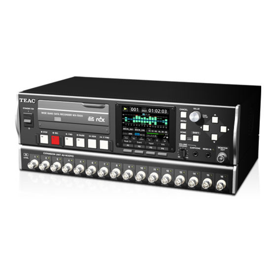
Page 8: Names And Functions Of Parts
4. Names and Functions of Parts 4-1. Front panels WX-7000 recording unit o Drive cover open AU-WXEPIO expansion unit... - Page 9 4.Names and Functions of Parts RDX indicator STANDBY/ON (¤) switch This shows the RDX status as follows. Press to turn the power on or put the unit into standby. Press the switch up to turn the power on. Press it down to put Indicator Meaning Explanation...
- Page 10 4. Names and Functions of Parts MONITOR OUT connector Input connectors This can be used to output a monitor signal, which can be the Use these to input measurement signals. input signal of any channel or the voice memos. SDHC card slot Insert SDHC cards here.
-
Page 11: Side Panels
AU-WXEPIO joint bars Built-in speaker The WX-7000 and AU-WXEPIO units are physically connected by This outputs voice memos. four joint bars. The lengths of the joint bars differ for the WX-7016, o When an earphone is connected to the earphone jack, no WX-7032, WX-7064, WX-7096 and WX-7128 models. -
Page 12: Rear Panels
4. Names and Functions of Parts 4-3. Rear panels WX-7000 recording unit K L M AU-WXEPIO expansion unit OPTION-1 slot EXPANSION OUT connector This slot is for an option card with a height of 20.5 mm. Connect this to the EXPANSION IN connector of the AU-WXEPIO below it using a connection cable. - Page 13 EXPANSION OUT connector Connect this to the EXPANSION IN connector of the AU-WXEPIO below it using a connection cable. EXPANSION IN connector Connect this to the EXPANSION OUT connector of the WX-7000 or AU-WXEPIO unit above it using a connection cable.
-
Page 14: Basic Operation
5-2. Stopping power to the system Check the connections between the recording unit (WX-7000) and Before turning the power off for the recording unit (WX-7000), eject the expansion units (AU-WXEPIO), as well as the AC adaptor connec- the RDX cartridge and SDHC card. If the power is turned off while tions and turn the STANDBY/ON switch to ON. -
Page 15: Status Changes
5. Basic operation 5-3. Status changes 5-3-1. Explanation of status change diagram entry Entries appear on the status change diagram in the following manner. Stopped Status Waiting for button input or setting Possible operations [ 0 REC] Status change (by button or menu) 5-3-2. -
Page 16: Recording
6. Recording 6-1. Order of procedures 6-4. Setting triggers In addition to manually starting and stopping recording, you can Set the recording conditions also set the system to start and stop recording using triggers and intervals. Set the recording destination o After recording with the fan stopped, wait at least 10 minutes before recording with the fan stopped again. -
Page 17: Recording Stopping Conditions
6. Recording Recording stopping conditions Start time Recording starts at the set time. Level trigger Recording time Use a level change for the set channel as a trigger. Recording continues for the set amount of time. External trigger When the input through the EXT TRIGGER IN connector becomes Interval time the H level (open or 2 V or more), recording stops. -
Page 18: Playback
7. Playback 7-1. Order of procedures 7-5. Searching by event Set the playback conditions When ready for playback, select the event number (EVENT), and use the VALUE knob to search by event number. Then, press the VALUE Select the playback file knob to start playback from the position of that event number. -
Page 19: Searching By Time
8. Settings 7. Playback 7-7. Searching by time 8-1. Menu screen item list When ready for playback, select the date and time (TIME), and search HOME Sampling series (SERIES) for the desired date and time. Then, press the VALUE knob to start Sampling frequency (SAMPLE) playback from the position of that date and time. - Page 20 8. Settings SYSTEM Sampling series (SAMPLING SERIES) Sampling frequency (SAMPLING FREQ.) Number of active channels (ACTIVE CHANNEL) Analog-digital conversion bit depth (AD BIT) Voice memo activation (VOICE MEMO) Monitoring output channel (MONITOR CHANNEL) Monitoring output range (MONITOR RANGE) Input settings (INPUT SETTING) Input range (INPUT RANGE) Coupling (COUPLING) :...
- Page 21 8. Settings FILE Recording le (RECORDING FILE) Media selection (DEVICE) Directory name (DIRECTORY) File name (FILE) Comment (COMMENT) Playback le (FILE OPEN) Media selection Directory name File name File information Playback mode Delete les (FILE DELETE) Format the media (FORMAT) Trigger mode (MODE) No triggers (NONE) Trigger recording (TRIGGER)
- Page 22 8. Settings MISC Set data shown on Home Screen (DISPLAY DATA) Set number of channels shown with bar meters (DISPLAY CH) Setting saving, loading and initialization (PARAMETER) Speaker output setting (SPEAKER) Fan activation (FAN) Sampling notation setting (NOTATION) Language setting (LANGUAGE) Network settings (NETWORK) Date and time settings (TIMESET) Display adjustment (LCD)
-
Page 23: Troubleshooting
Is compatible media loaded in the WX-7000? appears Has the media been formatted by the WX-7000? If not, use the WX-7000 to format it. When formatting media for the first time, format it using the WX unit. Are you using media that has been confirmed to work with the WX-7000? - Page 24 Phone: +1-323-726-0303 TEAC EUROPE GmbH. Bahnstrasse 12, 65205 Wiesbaden-Erbenheim, Germany Phone: +49-(0)611-7158-349 (EU Importer) TEAC SALES & TRADING Room 817, Xinian Center A, Tairan Nine Road West, Shennan Road, Phone: +86-755-88311561-2 (ShenZhen) CO., LTD. Futian District, Shenzhen, Guangdong Province 518040, China...
Need help?
Do you have a question about the WX-7000 and is the answer not in the manual?
Questions and answers