
Related Manuals for RACOM M!DGE3


Summary of Contents for RACOM M!DGE3
- Page 1 User manual M!DGE3 Cellular Router fw 2.0.13.0 2022-09-14 version 1.0 RACOM s.r.o. | Mirova 1283 | 592 31 Nove Mesto na Morave | Czech Republic www.racom.eu Tel.: +420 722 937 522 | E -mail: racom@racom.eu...
-
Page 3: Table Of Contents
7.1.2.3.6. DF1 ....................54 7.1.2.3.7. IEC101 ....................55 7.1.2.3.8. Mars-A ....................55 7.1.2.3.9. Modbus RTU ..................56 7.1.2.3.10. PR2000 .................... 57 7.1.2.3.11. Siemens 3964(R) ................58 7.1.2.3.12. SAIA S-bus ..................60 7.1.2.3.13. RDS ....................63 © RACOM s.r.o. – M!DGE3 Cellular Router... - Page 4 7.3.3.2. Destination NAT ..................106 7.3.3.3. Cooperation with other services ..............109 7.4. VPN ..........................109 7.4.1. IPsec ........................109 7.4.1.1. IPsec settings ..................... 111 7.4.1.2. IPsec associations ..................111 7.4.1.2.1. Traffic selector ................. 115 M!DGE3 Cellular Router – © RACOM s.r.o.
- Page 5 8.4.3. Ethernet statistics ....................158 8.4.4. Cellular statistics ....................159 8.4.4.1. Cellular interface statistics ................159 8.4.4.2. Cellular state statistics ................160 8.4.4.3. Cellular signal statistics ................160 8.5. Monitoring ......................... 160 8.5.1. Settings ........................161 © RACOM s.r.o. – M!DGE3 Cellular Router...
- Page 6 10.6.2. EU Declaration of Conformity RED ..............177 10.6.3. Simplified EU declaration of conformity ............... 177 10.7. Warranty ......................... 179 10.8. M!DGE3 maintenance ....................180 A. Abbreviations ..........................181 Revision History ..........................183 M!DGE3 Cellular Router – © RACOM s.r.o.
-
Page 7: Important Notice
© 2022 RACOM. All rights reserved. Sole owner of all rights to this User manual is the company RACOM s. r. o. (in this manual referred to under the abbreviated name RACOM). Drawing written, printed or reproduced copies of this manual or records on various media or translation of any part of this manual to foreign languages (without written consent of the rights owner) is prohibited. -
Page 8: Quick Guide
1. Quick guide M!DGE3 is a widely configurable and compact cellular router. All you have to do to put it into operation is to connect it to an antenna and a power supply and configure it using a PC (tablet, smartphone) and a web browser. - Page 9 ). The ETH/USB contains a built-in DHCP server, so if you have a DHCP client in your PC as most users, you do not need to set anything up. The default IP address of M!DGE3 unit, for access over the ETH/USB adapter, is 10.9.8.7.
-
Page 10: Product
IP devices, with Linux OS that have been designed with attention to detail, performance and quality. M!DGE3 is built into a rugged metal casing that allows for multiple installation possibilities, see Sec- tion 4.1, “Mounting”. M!DGE3 Cellular Router – © RACOM s.r.o. -
Page 11: Dimensions
Product 2.1. Dimensions Fig. 2.1: M!DGE3 dimensions © RACOM s.r.o. – M!DGE3 Cellular Router... - Page 12 Product Fig. 2.2: M!DGE3 Edge-bracket dimensions Fig. 2.3: M!DGE3 flat bracket dimensions For more information see Section 4.1.1, “DIN rail mounting” and Section 4.1.2, “Flat mounting”. M!DGE3 Cellular Router – © RACOM s.r.o.
-
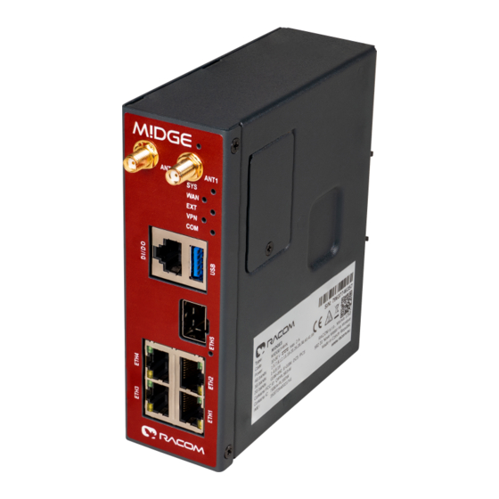
Page 13: Connectors
HW button is located on the front panel as well (close to the upper edge). Fig. 2.4: Connectors 2.2.1. Antenna An antenna can be connected to M!DGE3 via SMA female 50 Ω connect- M!DGE3 is equipped with two connect- ors. The ANT1 connector will be used for common transmitting and receiving single antenna installation. - Page 14 This rugged connector connects to a power supply and it contains control signals. A plug with screw- terminals and retaining screws for power and control connector is supplied with each M!DGE3. It is Tyco 7 pin terminal block plug, part No. 1776192-7, contact pitch 3.81 mm. The connector is designed for electric wires with a cross section of 0.5 to 1.5 mm...
- Page 15 The POWER pins labelled + and - serve to connect a power supply 10–50 VDC. The requirements for a power supply are defined in Section 4.6, “Power supply” and Chapter 9, Technical parameters. © RACOM s.r.o. – M!DGE3 Cellular Router...
- Page 16 The SFP modules listed in Accessories are thoroughly tested by RACOM and are guaranteed to function with M!DGE3 units. It is possible to use any other SFP module, but RACOM cannot guarantee they will be completely compatible with M!DGE3 units.
- Page 17 A In/Out M!DGE3 keeps pin 6 DSR at the level of 0 (state ON, approx. +6.2 V) by RS232 standard permanently. Expansion board 'C' (2 x RS232) The 2nd and 3rd COM ports are available when the Expansion board 'C' (2 x RS232) is installed. In such a case: The DI/DO connector is used as a connector for COM2 and COM3.
- Page 18 RxD COM3 TxD COM3 CTS COM2 RTS COM2 RxD COM2 TxD COM2 2.2.6. USB M!DGE3 uses USB 3.0, Host A interface. USB interface is wired as standard: Tab. 2.5: USB A Pinout Cable Assembly Signal Wire VBUS White Green Black...
- Page 19 • Pull below 1.1 VDC to activate (1.1 VDC / 1.9 VDC threshold hysteresis) • Max. 50 VDC 2.2.8. HW button Fig. 2.9: HW button HW button is placed on the right side of M!DGE3, next to the logo. © RACOM s.r.o. – M!DGE3 Cellular Router...
-
Page 20: Extension
• Press from 7 up to 20 seconds - Factory settings are performed on button release • Press more than 20 seconds - Nothing happens 2.2.9. SIM cards Two SIM card holders for Micro SIM (3FF) are available under the screwed cover on the M!DGE3 right side. Warning Disconnect M!DGE3 unit from a power supply before opening the cover and manipulating with SIM cards. -
Page 21: Gps
It is recommended to use both antennas (MIMO diversity) for the LTE connection. In case of using only one antenna, attach it to the ANT1 connector. 2.3.2. SIM card holders Two SIM card holders for Micro SIM (3FF) are available under the screwed cover on the M!DGE3 right side. 2.4. GPS M!DGE3 cellular router shall be equipped by the GPS receiver with time pulse output. - Page 22 Alarm of mPCIe connected equipment Permanently lit Pending Green Permanently lit Data receiving Yellow Permanently lit Data transmitting Alarm An Alarm is triggered by any event with severity Error or higher (see Section 8.3, “Events”). M!DGE3 Cellular Router – © RACOM s.r.o.
-
Page 23: Ordering Codes
S/N anytime later on. Possible values: Master – enables all functionalities of all possible SW feature keys; Part No.: M!DGE3-SW-MASTER Protocols – enables Dynamic routing (BABEL, OSPF, BGP); Part No.: M!DGE3-SW-PROTOCOLS © RACOM s.r.o. – M!DGE3 Cellular Router... - Page 24 Product Security – enables IPsec, GRE, RADIUS, Multiple users, Tamper detection; Part No.: M!DGE3- SW-SECURITY SFP – enables SFP interface; Part No.: M!DGE3-SW-SFP Type – specific product type Possible values: M!DGE3 Code – part of order code which is printed on Product label on the housing (SW keys are not HW dependent and can be ordered later on, so they are not printed on Product label).
-
Page 25: Accessories
Accessories 3. Accessories Whole accessory list is available on RACOM website. 1. Edge-bracket 2. Flat-bracket 3. USB adapters (ETH, WiFi) https://www.racom.eu/eng/products/radio-modem-ripex.html#accessories_ethusb 4. Demo case https://www.racom.eu/eng/products/radio-modem-ripex.html#accessories_democase https://www.racom.eu/eng/products/radio-modem-ripex.html#accessories © RACOM s.r.o. – M!DGE3 Cellular Router... -
Page 26: Installation
Installation 4. Installation Step-by-step checklist 1. Mount M!DGE3 into cabinet (Section 4.1, “Mounting”). 2. Install antenna (Section 4.2, “Antenna installation”). 3. Install feed line (Section 4.3, “Antenna feed line”). 4. Ensure proper grounding (Section 4.4, “Grounding”). 5. Run cables and plug-in all connectors except from the SCADA equipment (Section 2.2, “Connectors”). -
Page 27: Mounting
4.1. Mounting 4.1.1. DIN rail mounting M!DGE3 cellular modem is directly mounted to the DIN rail by a holder (which comes with the modem). Fig. 4.1: DIN rail Using this mounting M!DGE3 can be mounted in different angles (by 90° clockwise/counter clockwise). - Page 28 Installation For edged mounting to the DIN rail, Edge-bracket (optional accessory) is used. Use solely the M4×5 mm screws that are supplied. Fig. 4.2: Edged mounting to DIN rail M!DGE3 Cellular Router – © RACOM s.r.o.
- Page 29 4.1.2. Flat mounting For flat mounting directly to the support you must use the Flat bracket (an optional accessory). Use solely the M4×5 mm screws that are supplied. Fig. 4.3: Flat mounting using Flat bracket © RACOM s.r.o. – M!DGE3 Cellular Router...
-
Page 30: Antenna Installation
Use 50 Ω impedance cables only. The shorter the feed line, the better. If M!DGE3 is installed close to antenna, the data cable can be replaced by an Ethernet cable for other protocols utilizing the serial port, see Section 7.1.3, “Terminal servers”. -
Page 31: Connectors
M!DGE3 may be powered from any well-filtered 10 to 50 VDC power source. The supply must be capable of providing the required input for the projected RF output. To avoid radio channel interference, the power supply must meet all relevant EMC standards. -
Page 32: M!Dge3 In Detail
5.1.1. Detailed Description Generally, a Terminal server (also referred to as Serial server) enables connection of devices with a serial interface to a M!DGE3 over the local area network (LAN). It is a virtual substitute for the devices used as serial-to-TCP(UDP) converters. -
Page 33: Web Interface
(via LAN) or a high-speed WAN (e.g. Internet). The M!DGE3 which you are logged-in to in this way is called Local. Then you can manage any remote M!DGE3 in the network over-the-air in a throughput-saving way: all the static data (e.g. Web page graphic objects) is downloaded from the Local M!DGE3 and only information specific to the remote unit is transferred over the Radio channel. - Page 34 Note Web interface for M!DGE3 is identical to RipEX 2. The login page informs you about the Unit name and IP address of the M!DGE3 unit you are trying to log in. The login page allows changing of the language of the whole web interface (English language is default).
-
Page 35: Supported Web Browsers
6.2. Changes to commit M!DGE3 is capable of remembering changes, which were done in its configuration and collecting them in a Changes to commit "basket". All changes of configuration parameters are highlighted by different color. - Page 36 • Return to configuration - return to the last changed value. • Reset changes - all changes will be reset back to their previously set value (not default). • Send configuration - Apply (Save to radio unit) all the changes. M!DGE3 Cellular Router – © RACOM s.r.o.
-
Page 37: Notifications
Web interface 6.3. Notifications With M!DGE3 new way of showing important system events to the user is introduced. It is called Noti- fication Centre and is used consistently throughout the interface. Notification Centre is located on the top right corner of the interface. It exists in two forms: active notification display and full Notification Center. -
Page 38: User Menu
It is strongly recommended to change the default password. 6.5. Remote access M!DGE3 unit management is designed to work smoothly even when the unit under configuration is connected via relatively slow radio channel. In case of locally connected unit - direct configuration of the unit (accessing the unit IP address directly from the web browser) works fine. - Page 39 Remote access can be activated via click on the Remote access button. The connection to remote radio proceeds... The IP address of the actually connected M!DGE3 unit is displayed as part of the Remote access button. All the configuration settings are remotely available using standard web interface. Some of the Diagnostic features are available via local connection only.
-
Page 40: Refresh
This functionality is available on individual web pages of the graphical user interface by clicking of the purple box with the question mark on the right upper corner (or in the middle) of the screen (according to the width of the screen). M!DGE3 Cellular Router – © RACOM s.r.o. -
Page 41: Shortcuts
The content of the help is identical with the respective sub-chapter of the User manual. 6.8. Shortcuts Tab. 6.1: Table of shortcuts Shortcut Access to Ctrl+Alt+C Changes to commit Ctrl+Alt+N Notification center Ctrl+Alt+R Remote access © RACOM s.r.o. – M!DGE3 Cellular Router... -
Page 42: Settings
7.1. Interfaces 7.1.1. Ethernet M!DGE3 provides 5 physical Ethernet ports ETH1, ETH2, ETH3, ETH4 and ETH5. ETH1 - ETH4 ports are metallic. ETH5 port is a SFP port. There is a possibility to define an Ethernet bridge - a logical Network interface - by bridging (joining) together multiple physical Ethernet interfaces. - Page 43 Each Network interface can have attached one on more VLANs with one or more Subnets. Enable / Disable Enables / disables VLAN. VLAN ID Number {0 – 4094 }, default = 1 Specifies the VLAN ID according to IEEE 802.1Q © RACOM s.r.o. – M!DGE3 Cellular Router...
-
Page 44: Ports
Defines the speed and half / full duplex traffic. Note When several bridges are interconnected in the network, it is appropriate to switch-on Spanning Tree Protocol (ADVANCED-Interfaces-Ethernet-STP) to prevent bridge loops and build a loop- free logical topology. M!DGE3 Cellular Router – © RACOM s.r.o. -
Page 45: Com
Settings 7.1.2. COM Data incoming to the M!DGE3 unit from the COM port are received by the Protocol module. The Protocol module behavior depends on the Protocol selected. In case of Transparent protocol (available in Bridge mode only), it is transparently transmitted to the M!DGE3 network and send out through all COM ports with Transparent protocol selected. - Page 46 This parameter defines the maximum gap (in milliseconds) in the received data stream. If the gap exceeds the value set, the link is considered idle, the received frame is closed and forwarded to the network. MRU [B] Number {1 – 2047}, default = 1500 M!DGE3 Cellular Router – © RACOM s.r.o.
-
Page 47: Common Protocol Parameters
RTS/CTS (Request To Send / Clear To Send) hardware flow control (handshake) between the DTE (Data Terminal Equipment) and M!DGE3 (DCE - Data Communications Equipment) can be enabled in order to pause and resume the transmission of data. If RX buffer of M!DGE3 is full, the CTS goes down. - Page 48 UDP ports for COM or Terminal servers can be used or UDP port can be set manually. If the des- tination IP address belongs to a M!DGE3 and the UDP port is not assigned to COM or to a Terminal server or to any other special SW module running in the destination M!DGE3, the packet is discarded.
- Page 49 The Address translation is defined in a table. There are no limitations such as when the "Mask" translation is used. If there are more SCADA units connected via the RS485 interface, their multiple "Protocol addresses" are translated to the same IP address and UDP port pair. © RACOM s.r.o. – M!DGE3 Cellular Router...
-
Page 50: Individual Protocol Parameters
The None protocol switches the COM port off. All incoming data will be thrown away, No data will be send into the COM interface. 7.1.2.3.2. Transparent protocol Operates in Bridge mode only. All the traffic is bridged transparently to M!DGE3 network (see ??? for details). 7.1.2.3.3. Async link Async link creates an asynchronous link between two COM ports on different M!DGE3 units. -
Page 51: Comli
Note The COMLI protocol in the M!DGE3 is not fully compatible on COM port with M!DGE3 and MR modems. M!DGE3 implementation is not supporting “Intercharacter tx delay”. © RACOM s.r.o. – M!DGE3 Cellular Router... - Page 52 Timeout for checking of the duplicity of two following frames. Used when the very same frame is incoming via COM port within the timeout measured from the moment of dispatch of the previous frame. M!DGE3 Cellular Router – © RACOM s.r.o.
-
Page 53: Dnp3
Each frame in the DNP3 protocol contains the source and destination addresses in its header, so there is no difference between Master and Slave in terms of the M!DGE3 configuration. The DNP3 allows both Master-Slave polling as well as spontaneous communication from the remote units. -
Page 54: Df1
Settings 7.1.2.3.6. DF1 Each frame in the Allen-Bradley DF1 protocol contains the source and destination addresses in its header, so there is no difference between Master and Slave in the Full duplex mode in terms of M!DGE3 configuration. Duplex mode List box {Full duplex;... -
Page 55: Iec101
MARS-A was widely used by legacy RACOM radio modems in the MORSE system from the year 1999. The new implementation of this protocol in M!DGE3 is limited to the parts of the complex protocol which can be used together with modern packet type of radio routers: USER DATA (0x09) from router to the serial interface (e.g. -
Page 56: Modbus Rtu
7.1.2.3.9. Modbus RTU Modbus RTU is a serial polling-type communication protocol used by Master-Slave application. When M!DGE3 radio network run in Router mode, more Modbus Masters can be used within one Radio network and one Slave can be polled by more Masters. -
Page 57: Pr2000
Response timeout is active. Response timeout = 0 disables this feature. 7.1.2.3.10. PR2000 PR2000 is an abbreviation for the PROTEUS 2000 SCADA protocol. This protocol is used in Master- Slave applications. © RACOM s.r.o. – M!DGE3 Cellular Router... -
Page 58: Siemens 3964(R)
“SCADA address” as in UNI protocol. There is a handshake STX(0x02) – DLE(Ox10) on the start of communication and DLE+ETX – DLE on the end. This handshake is performed by M!DGE3 locally, it is not transferred over the M!DGE3 network. - Page 59 Address mode List box {Binary (1 B); Binary (2B LSB first); Binary (2B MSB first)}, default = "Binary (1 B)" M!DGE3 reads the Protocol address in the format and length set (in Bytes). Address position Specify the sequence number of the byte, where the Protocol address starts.
-
Page 60: Saia S-Bus
M!DGE3 checks (calculates itself) this byte while receiving a packet on COM. M!DGE3 transmits DLE (accepts the frame) only when the check result is OK. BCC byte is not transferred over the M!DGE3 network, it is calculated locally in the end M!DGE3 and appended to the received data. - Page 61 Break mode is available only with COM port, it is not implemented on TS (the break signal is not available there). The Break signal is controlled is very rough (with step of 100 ms) due to Linux kernel limitations. © RACOM s.r.o. – M!DGE3 Cellular Router...
- Page 62 0x85 0xC500 0xC5 0xC501 Note See details of the RACOM’s implementation on https://www.racom.eu/eng/sup- port/prot/sbus/index.html Mode of Connected device: MASTER Transmission control timeout [ms] Number {0 – 65535}, default = 11500 Master timeout. This timeout is reseted after receiving of an answer from Slave or a frame in- coming from the connected master.
-
Page 63: Rds
Number {0 – 31}, default = 3 Number of frame re-transmissions. Local response address Number {0 – 255}, default = 0 This address is used only with status query (0x51). Response of M!DGE3 is "0x54 <Local response address> 0x00". © RACOM s.r.o. – M!DGE3 Cellular Router... -
Page 64: Uni
Settings 7.1.2.3.14. UNI UNI is the 'Universal' protocol utility designed for M!DGE3. It is supposed to be used when the required application protocol is not available in M!DGE3 and the network communication is using addressed mode (which is a typical scenario). The key prerequisite is: messages generated by the Master applic- ation device must always contain the respective Slave address and the address position, relative to the beginning of the message (packet, frame), is always the same (Address position). -
Page 65: Terminal Servers
TCP messages and processed like it comes from a COM port. When data reaches the destination M!DGE3, it can be transferred to the RTU either via a serial interface or via TCP (UDP), using the Terminal server again. -
Page 66: Cellular
Up to 5 independent Terminal servers can be set up. Each one can be either TCP or UDP Type, TCP Inactivity is the timeout in seconds for which the TCP socket in M!DGE3 is kept active after the last data reception or transmission. As source IP address of a Terminal server will be used the IP address of the M!DGE3 ETH interface (Local preferred source address if exists see Section 7.2.1, “... -
Page 67: Main/Ext
Settings M!DGE3 optionally provides cellular WWAN interface using embedded cellular module. Two SIM cards are available, only one can be active at a time. APN must always be set up, all other parameters can keep their default values. 7.1.4.1. MAIN/EXT Enable / Disable cellular MAIN/EXT: Enables / Disables the cellular MAIN/EXT. -
Page 68: Parameters
List box {On; Off}, default = "Off" Enables / Disables automatic Profile switching. 7.1.4.1.2. Cellular profiles Set of defined profiles (at least one profile is required), which are setting parameters of requested service of the network (e.g APN). M!DGE3 Cellular Router – © RACOM s.r.o. - Page 69 4G (LTE) first; 4G (LTE) only; 3G/4G (UMTS/LTE) only}, default = "4G (LTE) first" Sets preferences and/or permission of the individual cellular network services. Header compression List box {On; Off}, default = "Off" © RACOM s.r.o. – M!DGE3 Cellular Router...
-
Page 70: Link Testing
(Link testing). Tests are in form of sending ICMP ping to defined ad- dress(es) and waiting for response. This section occurs only, if parameter Link testing is set to "On". M!DGE3 Cellular Router – © RACOM s.r.o. - Page 71 Repeat period [s] Number {3 – 3600}, default = 10 If the test results as failed, the connection is tested again after defined time period. Retries [No] Number {1 – 20}, default = 3 © RACOM s.r.o. – M!DGE3 Cellular Router...
-
Page 72: Profile Switching
After defined time period, the module will try to reconnect via the first profile again (independently on the profile queue). This section occurs only, if parameter Profile switching is set to "On". Fig. 7.2: Link testing scheme M!DGE3 Cellular Router – © RACOM s.r.o. -
Page 73: Sim1 And Sim2
The PIN is used only when PIN protection is On and the module requires the PIN. 7.1.4.3. Cooperation with other services Interface AUX was renamed to EXT. AUX might still be seen in some sections (e.g parameters Input / Output interface). © RACOM s.r.o. – M!DGE3 Cellular Router... -
Page 74: Status
Parameters Input interface and Output interface can filter the traffic either coming from WWAN or leaving to WWAN (List box WWAN or AUX). Only traffic coming through M!DGE3 (FORWARD) is filtered. • SNAT - parameter Output interface can filter the traffic (List box WWAN or AUX). -
Page 75: Routing
BABEL, OSPF and BGP standard routing protocols are available in M!DGE3 networks. 7.2.1. Static M!DGE3 works as a standard IP router with multiple independent interfaces: Radio interface, Network interfaces (bridging physical Ethernet interfaces), COM ports, Terminal servers, optional Cellular interface etc. -
Page 76: Loopback Addresses
Local preferred source address Local IP address used as a source address for packets originating in the local M!DGE3 unit being routed by this routing rule. It might be for example packets originating from the COM port or from the Terminal Server. -
Page 77: Babel
OSPF protocol description) with the following differences: • Works within one autonomous system • BABEL provides both wired and wireless type of network interface BABEL protocol is typically used in the networks containing radio hops. https://datatracker.ietf.org/doc/html/rfc6126.html#section-1.1 © RACOM s.r.o. – M!DGE3 Cellular Router... -
Page 78: Description
If configured limit of lost packets is exceeded, the line is considered down. • Wireless: assumes a variable connection quality. The price of the interface increases gradually witch each lost Hello packet until the line is declared down. Routing decision: https://www.racom.eu/download/hw/ripex/free/eng/1_application/ripex2-app-bab-en.pdf M!DGE3 Cellular Router – © RACOM s.r.o. -
Page 79: Common - Common Settings
Router ID IP address, default = 0.0.0.0 M!DGE3 unit acts in the BABEL network as a dynamic router. Every router is identified by an ID having the format of IP address. This IP address does not have to be ‘real’. -
Page 80: Network - Interfaces
Hot standby – “hstdby” GRE L3 – “gre_tunX” where ‘X’ is the tunnel number, starting from zero Cellular – “aux” Interface MTU must be 1280 Bytes or bigger in order to operate BABEL protocol correctly. M!DGE3 Cellular Router – © RACOM s.r.o. -
Page 81: Static Rules
Note Informational note. 7.2.2.4. Static rules Pre-defined static routing rules to be exported over the BABEL protocol. Maximum number of rules is 256. Active List box {On; Off}, default = "On" © RACOM s.r.o. – M!DGE3 Cellular Router... -
Page 82: Import Filter
Number {0 – 32}, default = 0 Mask to Number {0 – 32}, default = 32 Definition of the enabled range of the mask length of the processed routing rule. Examples: Rule 0.0.0.0/0{0,32} captures all IP ranges M!DGE3 Cellular Router – © RACOM s.r.o. -
Page 83: Export Filter
Active List box {On; Off}, default = "On" Enables / disables the filter rule. Filter network List box {Off; Match; Not match}, default = "Off" Method of the routing rule target range comparison. © RACOM s.r.o. – M!DGE3 Cellular Router... - Page 84 MED value filled in, the static Metric value is used. OSPF metric 1: Metric of OSPF type 1. If the rule does not have a metric value filled in, the static Metric value is used. M!DGE3 Cellular Router – © RACOM s.r.o.
-
Page 85: Ospf
(AS). OSPF Version 2 defined in RFC 2328 (1998) for IPv4 is im- plemented in the M!DGE3 router. OSPF provides Layer 2 dynamic routing. In the context of M!DGE3 networks it is typically used for the backhaul network routing. -
Page 86: Common - Common Settings
• It is possible to define exported routing rules aggregation or specific routing rule hiding. • It is possible to control the routing rules which are imported into the M!DGE3 unit from the OSPF protocol and those that are exported into the OSPF protocol from the unit by using ‘filters’. -
Page 87: Network - Areas And Interfaces - Interfaces
‘Type 1’. Hello interval Number {1 – 3600}, default = 10 Interval (in seconds) of sending Hello packets. The interval must be the same for the all participants of the given interface. © RACOM s.r.o. – M!DGE3 Cellular Router... -
Page 88: Network - Areas And Interfaces - Neighbors
List box {list of existing OSPF interfaces} OSPF interface the neighbor belongs to. The interface – Note value is used when defined. The in- terface – Interface value is used otherwise. IP address of the neighbor. M!DGE3 Cellular Router – © RACOM s.r.o. -
Page 89: Network - Areas And Interfaces - Networks
Metric type of the routing rule. Metric 1 is added to the path cost. Metric 2 stays apart and compared to metric 1 is always bigger. Metric Number {1 – 65535}, default = 1000 Routing rule metric value. © RACOM s.r.o. – M!DGE3 Cellular Router... -
Page 90: Import Filter
• Internal – internally generated rule, for example interface range • Inter-area – rule generated on the area border Filter OSPF tag List box {Off; Match; Not match}, default = "Off" Method of the OSPF routing rule OSPF tag comparison M!DGE3 Cellular Router – © RACOM s.r.o. -
Page 91: Export Filter
Mask to Number {0 – 32}, default = 32 Definition of the enabled range of the mask length of the processed routing rule. Filter protocol List box {Off; Match; Not match}, default = "Off" © RACOM s.r.o. – M!DGE3 Cellular Router... -
Page 92: Bgp
It is possible to prescribe routing rules toward this router which will be spread across the network (Static rules). It is possible to control the routing rules which are imported into the M!DGE3 unit from the BGP protocol and those that are exported into the BGP protocol from the unit by using ‘filters’. -
Page 93: Common - Common Settings
IP address, default = 0.0.0.0 M!DGE3 unit acts in the BGP network as a dynamic router. Every router is identified by an ID having the format of an IP address. This IP address does not have to be ‘real’. Router ID is shared with the OSPF protocol. -
Page 94: Neighbors
This is typical for eBGP routers. "Multihop" means connection over the multiple routers. This is typical for iBGP routers. MD5 authentication List box {On; Off}, default = "Off" Enables BGP packets authentication using TCP MD5 Signature extension. Password String {up to 128 char} M!DGE3 Cellular Router – © RACOM s.r.o. -
Page 95: Static Rules
"Internal" overwrites only the rules from the local AS. "External" overwrites only the rules from the other AS. 7.2.4.4. Static rules Pre-defined static routing rules to be exported over the BGP protocol. Maximum number of rules is 256. © RACOM s.r.o. – M!DGE3 Cellular Router... -
Page 96: Import Igp Filter
Filtering based on the BGP Path (routing rule path over different AS). "Is empty" – defines an empty path (routing rule from the local AS). "Contain" – defines paths containing specific AS. Path position List box {Any; Neighbor; Source}, default = "Any" M!DGE3 Cellular Router – © RACOM s.r.o. -
Page 97: Export Igp Filter
IP address, default = 0.0.0.0/0 IP address and mask defines the network prefix to be compared Mask from Number {0 – 32}, default = 0 Mask to Number {0 – 32}, default = 32 © RACOM s.r.o. – M!DGE3 Cellular Router... -
Page 98: Import Out Rules
Limit of the accepted routing rules from the neighbor. The limit applies before this Import OUT filter. Excess rules are dropped. Active List box {On; Off}, default = "On" Enables / disables the filter rule. Note Informational note. M!DGE3 Cellular Router – © RACOM s.r.o. -
Page 99: Export Out Filter
Defines what action is taken on the routing rules which were not captured (i.e. fallback) in the Export OUT filter. Active List box {On; Off}, default = "On" Enables / disables the filter rule. Note Informational note. © RACOM s.r.o. – M!DGE3 Cellular Router... - Page 100 -1}, default = 65000 The number of the AS searched for. Action List box {Accept; Reject; Pass}, default = "Accept" Defines what action is taken on the routing rule. "Pass" continues in processing. M!DGE3 Cellular Router – © RACOM s.r.o.
-
Page 101: Firewall
The traffic to/from other MAC addresses is blocked. Active List box {Off; On}, default = "On" If "On", Layer 2 Linux firewall is activated. Interface List box {All; ETH1..ETH5}, default = "All" IPv4 MAC address © RACOM s.r.o. – M!DGE3 Cellular Router... -
Page 102: Firewall L3
List box {Deny; Allow}, default = "Deny" Destination IP / Mask Destination port (from) / Destination port (to) Interval of destination ports Output interface List box {All; Radio; All ETH; Other}, default = "All" M!DGE3 Cellular Router – © RACOM s.r.o. -
Page 103: Nat - Network Address Translation
L3 Firewall settings do not impact packets received and redirected from/to Radio channel. The problem described in NOTE 2 will not happen, if the affected M!DGE3 router is a radio repeater, i.e. when it uses solely the radio channel for input and output. - Page 104 If only one port is required, set both parameters to the same number. These parameters occur only, if parameter “Procotol” is set to “UDP” or “TCP”. Destination IP / Mask IP address, default = 0.0.0.0/0 M!DGE3 Cellular Router – © RACOM s.r.o.
- Page 105 Rewrite source port Number {0 – 65535}, default = 0 Defines a new source port (rewriting multiple defined ports into one). Value 0 means, that the source port is not changed. Note Informational note. © RACOM s.r.o. – M!DGE3 Cellular Router...
-
Page 106: Destination Nat
Protocol number Number {0 – 255}, default = 1 This parameter occurs only, if parameter “Protocol” is set to “Other”. Source IP / Mask IP address, default = 0.0.0.0/0 Defines the source IP subnet. M!DGE3 Cellular Router – © RACOM s.r.o. - Page 107 • Port to IP address (PORTMAP): Range mapping of destination ports (parameters “Destination port from”, “Destination port to”). New range mapping of destination ports origins in parameter “Rewrite destination IP”. It can be additionally overwritten to parameter “Rewrite destination port”. © RACOM s.r.o. – M!DGE3 Cellular Router...
- Page 108 Defines a new destination address. Value 0.0.0.0/0 means, that the destination address is not changed. Rewrite destination port Number {0 – 65535}, default = 0 Defines a new destination port (rewriting multiple defined ports into one). Value 0 means, that the destination port is not changed. M!DGE3 Cellular Router – © RACOM s.r.o.
-
Page 109: Cooperation With Other Services
Although there are 2 modes of operation, M!DGE3 only offers a Tunnel mode. In Tunnel mode, the entire IP packet is encrypted and authenticated. It is then encapsulated into a new IP packet (ESP –... - Page 110 NAT-T (NAT Traversal) or MOBIKE (MOBile IKE) are active, the UDP port 4500 is used instead. Note NAT-T is automatically recognized by IPsec implementation in M!DGE3. The IPsec tunnel is provided by Security Association (SA). There are 2 types of SA: •...
-
Page 111: Ipsec Settings
(corresponding actions are initialized). In the case when Detection is not enabled, a connection loss is discovered when regular key exchange process is initiated. © RACOM s.r.o. – M!DGE3 Cellular Router... - Page 112 This parameter is valid if IKEv2 is used. It determines the next action after IKE SA has expired. When enabled: the new IKE SA is negotiated including new peer authentication. When disabled: only the new keys are exchanged. M!DGE3 Cellular Router – © RACOM s.r.o.
- Page 113 Unfortunately, the more frequent the key exchange, the higher the network and CPU load. Note The M!DGE3 unit load is seriously affected when key exchange is in process. Phase 2 – IPsec Certain parameters are shared by all subordinate CHILD SA. IPsec Security Association provides...
- Page 114 Note The M!DGE3 unit load is seriously affected when key exchange is in process. PSK (Pre-shared key) authentication is used for IKE SA authentication. The relevant peer is identified using it's "Peer ID". The key must be the same for both local and peer side of the IPsec.
-
Page 115: Traffic Selector
Remote network address / Mask Destination IP address and mask of the packets to be captured and forwarded to the encrypted tunnel. 7.4.1.3. Advanced menu Several additional parameters are available in menu: ADVANCED / VPN / IPsec © RACOM s.r.o. – M!DGE3 Cellular Router... - Page 116 Settings M!DGE3 Cellular Router – © RACOM s.r.o.
-
Page 117: Gre L2
Ethernet frames of the bridge and sends them to the other end of the tunnel. It enables to build bridge via the complex network and combine the local partial networks to one network. GRE L2 tunnel can be used to tunnel the IPv6 traffic over the M!DGE3 IPv4 network. © RACOM s.r.o. – M!DGE3 Cellular Router... -
Page 118: Gre L3
GRE L3 tunnel works as an additional unit’s interface with its own IP address (and mask). The routing rules are used for sending packets to this interface. It bridges part of the network, so it seems to be one hop for the user traffic. M!DGE3 Cellular Router – © RACOM s.r.o. -
Page 119: Security
(Path MTU discovery). 7.5. Security User authentication is required to access M!DGE3 unit management. There are two types of user au- thentication which differ in the user account location: Local authentication – user accounts are stored directly in the M!DGE3 unit Remote authentication –... - Page 120 Read-only Write Write Write Firmware Non-visible Write Write Write Monitoring Non-visible Write Write Write DIAGNOSTICS Tools Read-only Write Write Write At least one Administrator type of account must be defined in the unit. M!DGE3 Cellular Router – © RACOM s.r.o.
-
Page 121: User Access
Note When changing settings of HTTP or HTTPS, linux service LigHTTPd restarts. Because of that, the waiting time period for update in the web ends a returns Error: Connection to device timed out. © RACOM s.r.o. – M!DGE3 Cellular Router... -
Page 122: Local Authentication
+ Add user account button invokes new user account creation dialog: Username String {1–128 char}, default = <empty> New Username. Every username in the unit must be unique. Password String {5–128 char}, default = <empty> M!DGE3 Cellular Router – © RACOM s.r.o. -
Page 123: Settings
The minimum number of lowercase letters (English letters) which are required in the user password Min. UPPERCASE letters [No] Number {0 – 5}, default = 0 The minimum number of uppercase letters (English letters) which are required in the user password © RACOM s.r.o. – M!DGE3 Cellular Router... -
Page 124: Remote Authentication
RADIUS accounts can be mapped to one of the four user roles. This is either managed by the server itself or by local M!DGE3 settings. Local accounts are checked first and if the account does not exist, RADIUS accounts will be used. If the RADIUS server is not accessible, users may use the local username/password to “fall back”... -
Page 125: Tamper Reset
Management-Privilege-Level the static account level option (for all users) has to be used. 7.5.4. Tamper reset Tamper is a detection service, which is triggered, when the M!DGE3 chassis is physically opened. There are 2 contacts (securing top and bottom casing) and the event is triggered even if the unit is without power. - Page 126 For Tamper reset see SETTINGS/Security/Tamper reset and click the "Reset tamper" button. Note The unit must be re-assembled before Tamper reset, otherwise it returns an error. Whole process can take a while and ends by rebooting the unit. M!DGE3 Cellular Router – © RACOM s.r.o.
-
Page 127: Device
The USB service interface primary purpose is to provide unit service and management access. Ethernet or WiFi connection can be established using an external ETH/USB or WiFi adapter. Please note that only adapters listed in https://www.racom.eu/eng/products/radio-modem-ripex.html#accessories_ethusb can be used. © RACOM s.r.o. – M!DGE3 Cellular Router... - Page 128 DHCP server assigns IP addresses to connected clients in the range defined by DHCP pool start and DHCP pool end (inclusive). WiFi WiFi AP parameters can be customized. SSID automatically List box {On; Off}, default = "On" M!DGE3 Cellular Router – © RACOM s.r.o.
-
Page 129: Time
If the unit is synchronized to a time source and the unit (synchronized) time differs from the unit RTC time (by more than 8 seconds), the RTC time is updated. Note Each unit can serve as NTP server for further IP equipment, this functionality is always on. © RACOM s.r.o. – M!DGE3 Cellular Router... - Page 130 NTP server minimum polling time Minimal period of the NTP server queries. NTP client is allowed to prolong this time in case of poor quality of the server or connection to the server. M!DGE3 Cellular Router – © RACOM s.r.o.
-
Page 131: Configuration
The full configuration backup can only be issued by a user with the Administrator (role_admin) access privileges. The same user access limit applies when the configuration is restored (i.e. the full configuration Restore can only be issued by a user with the Administrator (role_admin) access privileges). © RACOM s.r.o. – M!DGE3 Cellular Router... - Page 132 Restores all configuration parameters to default setup (including monitoring settings) Deletes user database (only default user "admin" with default password will remain). Logout from station will apply. Deletes all diagnostic logs and statistics M!DGE3 Cellular Router – © RACOM s.r.o.
- Page 133 Note Basic data such as Code, Region, SW keys will always remain in the unit. Warning This action can take up to two minutes - do not power off the unit until finished. © RACOM s.r.o. – M!DGE3 Cellular Router...
- Page 134 Settings Tab. 7.3: Configuration versions CNF version FW version 2.0.13.0 M!DGE3 Cellular Router – © RACOM s.r.o.
-
Page 135: Events
Events can also generate an SMS notifications, which are being sent to a defined phone number (see Section 7.6.5, “SMS”). 7.6.4. SNMP SNMP (Simple Network Management Protocol) implementation in M!DGE3 provides three SNMP ver- sions: v1, v2c and v3. © RACOM s.r.o. – M!DGE3 Cellular Router... - Page 136 String {1–32 char}, default = <empty>Username for SNMPv3. When v3 protocol is selected, this parameter is mandatory. Security level List box {NoAuthNoPriv; AuthNoPriv; AuthPriv}, default = "NoAuthNoPriv" The v3 protocol security level. Switches on/off Authentication (Auth) and the SNMP data encryption (Priv). M!DGE3 Cellular Router – © RACOM s.r.o.
- Page 137 List box {Default; User defined}, default = "Default" Engine Id serves for unique identification of the SNMP instance (i.e. the M!DGE3 unit) according to RFC3411. When the "Default" Engine ID mode is selected the MAC address of the Eth1 interface is used for the unique part of the Engine Id (the whole Engine ID example: 800083130302a92006ef).
-
Page 138: Sms
Number {1 – 65535}, default = 162 Notification packets destination port. 7.6.5. SMS M!DGE3, fully connected into the cellular network (status CONNECTED), is capable of receiving and sending SMS. • Receiving and sending SMS is provided by a linux service. -
Page 139: Parameters
Allows to accept commands from defined phone number. Note This parameter will work only if parameter SMS commands EXT is enabled. Send notifications {On; Off}, default = "On" Allows to send notifications to defined phone number. © RACOM s.r.o. – M!DGE3 Cellular Router... -
Page 140: Sms Commands
This command does not generate an automatic reply. 7.6.6. SW keys Certain M!DGE3 features needs to be activated by a SW key to be available. When the respective SW key is not present, the feature cannot be configured. If the feature is enabled in a configuration backup file and the file is loaded to a unit which is not equipped with the respective key, the configuration is refused (no changes are made in the unit). - Page 141 SW key is unique for the specific unit (specific serial number). Use Choose File dialog to select the file and Install key button to install the key(s) to unit. Differences with the previous generation of M!DGE3: - SW keys are always installed as a file (there is not a clipboard option)
-
Page 142: Firmware
Unit firmware defines the unit functionality. There are several principles for managing the firmware in the running network: • Maintain the same version of firmware in the network (recommended). M!DGE3 units are able to cooperate with different versions of firmware running, but using the same firmware version in all units is the best way to keep the network maintenance simple. - Page 143 4. Click the Upload firmware button to transfer the firmware file into the unit. The upload can take a long time – depending on the connection speed between the management PC and the M!DGE3 unit. In case of slow connection and file transfer longer than 120 s, the web browser will shut down the connection and the action will not finish successfully.
-
Page 144: Advanced
M!DGE3. Please note, that M!DGE3 is a very powerful device and it really shows all parameters in the Advanced section. When you visit the page for the first time, you will see a search field and below a tree of configuration pages. - Page 145 Settings Be careful when adjusting settings in Advanced section and review the “Changes” page in detail before sending changes to the device. © RACOM s.r.o. – M!DGE3 Cellular Router...
-
Page 146: Diagnostics
Diagnostics 8. Diagnostics 8.1. Overview The Overview section serves to give general information about the M!DGE3. 8.1.1. Measurements Section Overview - Measurements contains current data measurement (obtained from sensors). • Card Temperature - provides data about temperature (on CPU, modem and radio). -
Page 147: Statistics
Provides a complete information extract about all active interfaces (addresses, details and statistics included). All interfaces used by the linux router (including all internal interfaces like npi, loop, ag, ip6tnl, etc.) are displayed in this section. © RACOM s.r.o. – M!DGE3 Cellular Router... - Page 148 Diagnostics Intefaces used in M!DGE3 units are in general either Bridged ports (BP-L2) or Routed interfaces (RI- L3). All interfaces used by the linux router (internal interfaces excluded) are displayed in the following list. if_<LanIface_Name> LAN bridge interface RI-L3 type (SETTINGS>Interfaces>Ethernet>Network interfaces)
-
Page 149: Routing
• BGP - data extract of status of all BGP protocol instances. Displays data called by following linux commands: "birdcl show protocol '"bgp*"'", "birdcl show protocol all '"bgp*"'", "birdcl show route all table bgp_ipv4". © RACOM s.r.o. – M!DGE3 Cellular Router... -
Page 150: Firewall
Displays data called by following linux commands “iptables -nvL --line-numbers”. 8.2.3.3. NAT Displays data called by following linux commands: "iptables" - displays user routing rules "iptables -t nat -nvL postrouting_user" – data about SNAT M!DGE3 Cellular Router – © RACOM s.r.o. -
Page 151: Quality Of Service
• Status and statistics of front disciplines - displays data called by linux command “tc qdisc show”. • Status and statistics of classes - displays data called by linux command “tc class show”. • Status and statistics of filter - displays data called by linux command “tc filter show”. © RACOM s.r.o. – M!DGE3 Cellular Router... -
Page 152: Device
Provides general information about the unit (device). 8.2.5.1. System information Basic unit information is provided. • Product code - Identifies the unit hardware. • Serial number - Unique unit identification number • FW version - Currently installed unit firmware M!DGE3 Cellular Router – © RACOM s.r.o. -
Page 153: Advanced Information
This menu serves for collecting data, either from local or remote station and storing them into a package (file). Diagnostic package serves primarily as a help tool, for RACOM’s technical support in case of any potential unit issues. Minimum size of a package is 5kB. Maximum size depends on the amount of radio links contained in the statistics. -
Page 154: Events
Older events should be displayed using Load more button click, the events which occur during the viewing of this window can be loaded by using Load newer button. Alarms are displayed in red color, warnings in orange, notices in black and debugs in gray. M!DGE3 Cellular Router – © RACOM s.r.o. -
Page 155: Statistics
Debug 8.4. Statistics M!DGE3 unit permanently monitors various system 'channels'. There are several types of those channels: Physical interfaces (Ethernet ports, serial ports, radio interface, additional module interface (e.g. LTE module) when installed), virtual interfaces (e.g. VLAN interfaces) and HW sensors (CPU temperature, supply voltage, ...). -
Page 156: Parameters
“More options” fast presets (from several minutes to several days). Button “Set Current Time” sets current time to both From and To fields to ease current unit status diagnostics. There are following sets of statistical data available in the unit: • M!DGE3 Cellular Router – © RACOM s.r.o. -
Page 157: Serial Protocol Statistics
'Correct' and 'Drop' Bytes provides the total amount of Bytes on the physical interface. Rx direction: from the connected (at the COM or ETH port) external device to the M!DGE3 unit (i.e. from the COM port module or Terminal server module to the Router module). Tx direction: from the M!DGE3 unit to the external device. -
Page 158: Ethernet Statistics
Only correctly received frames are handled. The counters correspond to the specific IP protocol types. Rx direction: from the physical Ethernet port to the M!DGE3 unit (i.e. to the Router module). Tx direction: from the M!DGE3 unit to the physical Ethernet port. -
Page 159: Cellular Statistics
Layer 2 Ethernet frame (i.e. all IP headers are counted). IPv4 other - Packets not handled by the previous counters (e.g. VLAN, services, GRE, IPsec (ESP), ...). IPv6 - IPv6 packets are handled separately. © RACOM s.r.o. – M!DGE3 Cellular Router... -
Page 160: Cellular State Statistics
– average / standard deviation / minimum / maximum value. 8.5. Monitoring Monitoring is an advanced on-line diagnostic tool, which enables a detailed analysis of communication over any of the M!DGE3 router interfaces. In addition to all the physical interfaces (RADIO, ETHs, M!DGE3 Cellular Router – © RACOM s.r.o. -
Page 161: Settings
On the monitoring is still running in the background. The monitoring screen accordingly has two main parts - Setting and Output 8.5.1. Settings Save button - saves the new settings of the monitoring parameters. © RACOM s.r.o. – M!DGE3 Cellular Router... -
Page 162: Overview
List box {LOW; NORMAL; HIGH; UNLIMITED}, default = "NORMAL" Monitoring bandwidth limit to prevent overload of management link between client PC and the M!DGE3 unit. LOW (up to ~300 kb/s), NORMAL (up to ~800 kb/s), HIGH (up to ~2 Mb/s), UNLIMITED (up to ~8 Mb/s) - Page 163 List box {On; Off}, default = "Off" Displays (enable) / omits (disable) L2 headers in the monitoring output Include reverse List box {On; Off}, default = "Off" Enable/disable reverse traffic (e.g. TCP reply to a request) monitoring. © RACOM s.r.o. – M!DGE3 Cellular Router...
-
Page 164: General
Download button – downloads file to a connected computer. The default name contains of the Unit name, date and time of the begin and day and time of the end of the monitoring. Before downloading you have to stop recording. M!DGE3 Cellular Router – © RACOM s.r.o. -
Page 165: Console Output
BABEL, OSPF and BGP shows all rules set for individual dynamic protocols. 8.7. Tools Set of diagnostic tools 8.7.1. ICMP ping All parameters used by standard ICMp ping are available. Start / Stop button starts / stops pinging. © RACOM s.r.o. – M!DGE3 Cellular Router... -
Page 166: Routing
• Next hop (gateway) address (example: via 192.168.141.254) • Next hop interface (example: dev if_bridge) • Outgoing packet Source address (example: src 192.18.141.210) 8.7.3. System Reboot button Performs unit cold restart (power cycle equivalent). M!DGE3 Cellular Router – © RACOM s.r.o. -
Page 167: Syslog
Only the events with set severity (and higher) will be send to the Syslog server. Severities for indi- vidual Events can be set in menu ADVANCED/Device/Events/Events Login attempt List box {On; Off}, default = "Off" Switches whether login attempts (both successful and unsuccessful) will be sent to the SYSLOG server. © RACOM s.r.o. – M!DGE3 Cellular Router... -
Page 168: Technical Parameters
4G LTE Frequency bands for expansion board Band 1 (2100 MHz), Band 2 (1900 MHz), Band 3 (1800 MHz), 'W' Cellular Band 4 (2100 MHz), Band 5 (850 MHz), Band 7 (2600 MHz), M!DGE3 Cellular Router – © RACOM s.r.o. - Page 169 IP40, for indoor use only MTBF (Mean Time Between Failure) > 900 000 hours (> 100 years) Service life of system >= 15 years Operating temperature −40 to +70 °C ( −40 to +158 °F) © RACOM s.r.o. – M!DGE3 Cellular Router...
- Page 170 Trap / Inform alarms generation as per settings Client / Server Monitoring Real time analysis of all interfaces (ETH 1-5 , COM 1-3, TS 1-5) and internal interfaces between software modules, see details M!DGE3 Cellular Router – © RACOM s.r.o.
- Page 171 As needed, typically up to 100 m STP CAT 5e Optical Ethernet As needed, typically up to 2 km Optical fibre Max. 2 m USB3 DI / DO As needed STP CAT 5e © RACOM s.r.o. – M!DGE3 Cellular Router...
- Page 172 +0.12 W @ 100BaseT +Ethernet +0.5 W @ 1000BaseT per Eth interface with connected equipment +1st COM +0.2 W +GNSS +0.15 W +0.1 W Rx +0.3, Tx +3.0 W +SFP module typ. +1.0 W M!DGE3 Cellular Router – © RACOM s.r.o.
-
Page 173: Safety, Regulations, Warranty
The M!DGE3 cellular routers must not be opened. Only the replacement of the SIM card is permitted. Voltage at all connectors of the communication module is limited to SELV (Safety Extra Low Voltage) and must not be exceeded. -
Page 174: High Temperature
Safety, regulations, warranty 10.2. High temperature If the M!DGE3 is operated in an environment where the ambient temperature exceeds 55 °C, the M!DGE3 must be installed within a restricted access location to prevent human contact with the enclosure heatsink. 10.3. Battery disposal Battery Disposal - This product may contain a battery (e.g. - Page 175 (typically the files COPYING or LICENSE). You can obtain applicable machine-readable copies of source code of this software under GPL or LGPL li- censes on contacts listed on https://www.racom.eu. This product also includes software developed by the University of California, Berkeley and its contributors.
-
Page 176: Eu Compliance
Safety, regulations, warranty 10.6. EU Compliance 10.6.1. RoHS, WEEE and WFD Fig. 10.1: EU Declaration of Conformity RoHS, WEEE M!DGE3 Cellular Router – © RACOM s.r.o. -
Page 177: Eu Declaration Of Conformity Red
С настоящото RACOM s.r.o. декларира, че този тип радиосъоръжение M!DGE3 е в съответствие с Директива 2014/53/ЕС. Por la presente, RACOM s.r.o. declara que el tipo de equipo radioeléctrico M!DGE3 es conforme con la Directiva 2014/53/UE. © RACOM s.r.o. – M!DGE3 Cellular Router... - Page 178 Safety, regulations, warranty Tímto RACOM s.r.o. prohlašuje, že typ rádiového zařízení M!DGE3 je v souladu se směrnicí 2014/53/EU. Hermed erklærer RACOM s.r.o., at radioudstyrstypen M!DGE3 er i overensstemmelse med direktiv 2014/53/EU. Hiermit erklärt RACOM s.r.o., dass der Funkanlagentyp M!DGE3 der Richtlinie 2014/53/EU entspricht.
-
Page 179: Warranty
The serviced equipment shall be returned by RACOM to the customer by prepaid freight. If circumstances do not permit the equipment to be returned to RACOM, then the customer is liable and agrees to reim- burse RACOM for expenses incurred by RACOM during servicing the equipment on site. When equipment does not qualify for servicing under warranty, RACOM shall charge the customer and be reimbursed for costs incurred for parts and labour at prevailing rates. -
Page 180: M!Dge3 Maintenance
Check if internal temperature alarm has been triggered Monthly Check that firmware is latest stable version – upgrading FW As required recommended when new features required If you are unsure on any of the above, please contact RACOM technical support. M!DGE3 Cellular Router – © RACOM s.r.o. -
Page 181: Abbreviations
Request To Send https Hypertext Transfer Protocol Secure Remote Terminal Unit Internet Protocol Receiver Local Area Network SCADA Supervisory control and data acquisition Line-of-sight Software Defined Radio Media Access Control SNMP Simple Network Management Protocol © RACOM s.r.o. – M!DGE3 Cellular Router... - Page 182 Abbreviations Transmission Control Protocol Terminal server 5 Transmitter User Datagram Protocol VSWR Voltage Standing Wave Ratio WEEE Waste Electrical and Electronic Equipment M!DGE3 Cellular Router – © RACOM s.r.o.
-
Page 183: Revision History
While every reasonable effort has been made to ensure the accuracy of this publication, product improvements may also result in minor differences between the manual and the product shipped to you. Revision 1.0 2022-09-12 First issue © RACOM s.r.o. – M!DGE3 Cellular Router...
Need help?
Do you have a question about the M!DGE3 and is the answer not in the manual?
Questions and answers