Advertisement
Quick Links
Installation and operation instructions
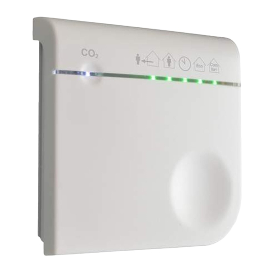
VMS-47C55 – RF-CO
A: Status LED
1. How to use this manual
This manual is intended as a reference book by which qualified
installers can install the VMS-47C55 (henceforth called "device") and
users can use the device for its intended purpose. Make sure you
have read and understood the manual before you install and/or use
the
device.
1.1 Intended use
The device is designed for following purposes:
1.
To set the level of ventilation through the fan speed, based on
user input or measured CO
2.
To set parameters for the ventilation control.
Every other or further use is not in conformance with the intended
use.
1.2 Working principle
The device communicates with the ventilation system using wireless
communications, to control the ventilation. Via the button and LEDs,
you can read and set the mode of control that the ventilation system
currently is in. When in Eco mode or Comfort mode, the device
requests the level of ventilation based on the amount of CO
1.3.1 Ventilation speeds and modes
The ventilation system runs in one of the following modes. In each of
these modes, the control device sets the ventilation system to a
configured level of
ventilation.
Mode
Away
Home
Timer
Auto
Auto Eco
Auto
Comfort
The device drives the fan based on the highest of values sent by the
bound wireless sensor(s).
When you start the timer mode from this device, the ventilation will be
active for 30 minutes.
1.3.2 CO
Setpoint
2
The device continuously measures the level of CO
compares the measured value to a configured setpoint. The device
controls the ventilation accordingly to keep the measured CO
below the requested level. When in Comfort mode, the requested
level is equal to the configured value. In Eco mode, the requested
level is 250 ppm above the configured value.
The device stores the configured fan speed values in the
ventilation system
and requests them from there.
The device stores the CO
communicate this with any other device.
sensor
2
B: Mode LED
C: Touch button
level.
2
Fan speed
Low fan speed
Medium fan speed
High fan speed, for a restricted duration
(ECONOMIC mode) Between Low fan
speed and high fan speed based on
measured values
Between Low fan speed and high fan
speed based on measured values
in the air and
2
setpoint itself and does not
2
1.4 Admonitions
'Warning' identifies a hazard that could lead to personal
injury, including death.
'Note' is used to highlight additional information.
2. Content delivery
• RF-Sensor (VMS-47C55)
• Battery
• Mounting screws
• Mounting plugs
• Manual
3. Safety
The device meets the following EC
•
EMC directive:
•
Low voltage directive:
•
RTTE directive:
•
RoHS directive:
•
WEEE directive:
4. Signs on the device
Caution. Check the instructions for use for important
cautionary.
Danger: risk of electric
IEC 61140 protection Class II (double insulated)
CE marking of
Dispose according to European Community
Directive 2012/19/EU
General safety instructions
This device was designed and manufactured to ensure
maximum safety during installation, operation and service.
Always read these safety instructions before installing,
in the
air.
2
maintaining, or servicing the product, and strictly comply with
these instructions. Parts of the device carry mains power, which
is a potential lethal voltage. Disconnect power at supply line,
circuit breaker or fuse before installing, servicing, or removing
the device. The device is designed for indoor use only. Do not
expose the device to rain or moisture, to avoid short circuit.
Short circuit may cause fire or electric shock hazard. Operate
the device between 0°C and 40°C.
For cleaning of the device use a soft damp cloth only. Never use
any abrasive or chemical cleaner. Do not paint the device.
4.Visual signals
Start up
System status
Mode selection
level
2
Start up
Mode selection
Away
Home
Timer
Auto Eco
Auto
Comfort
directives:
2014/30/EC
2014/35/EU
2014/53/EU
2011/65/EU
2012/19/EU
shock.
conformity.
(WEEE).
Status LED
White
Continuous
Green
Continuous
Yellow
Continuous
Red
Continuous
1 flash
3 flashes
4 flashes
Off
Mode LED
On
On
On
*
*
*
1
1
2
2
1
.
<800 ppm
800-1900 ppm
>1900 ppm
Comm. Error
Fan error
CO
sensor error
2
Auto
Auto
Eco
Comfort
On
On
*
*
Advertisement

Subscribe to Our Youtube Channel
Related Manuals for inventum VMS-47C55


Summary of Contents for inventum VMS-47C55
- Page 1 WEEE directive: 2012/19/EU This manual is intended as a reference book by which qualified installers can install the VMS-47C55 (henceforth called “device”) and 4. Signs on the device users can use the device for its intended purpose. Make sure you Caution.
- Page 2 Status LED and Mode LEDs show the status of the system. 230VAC +-10%, Mains Power Source 50Hz You are not allowed to use the device outside Max. power consumption of Europe 0.25 to 2.5 mm 2 Wire diameter: Inventum Technologies BV – VMS-47C55-EN-V1...
Need help?
Do you have a question about the VMS-47C55 and is the answer not in the manual?
Questions and answers