
Related Manuals for technoswitch TEC247


Summary of Contents for technoswitch TEC247
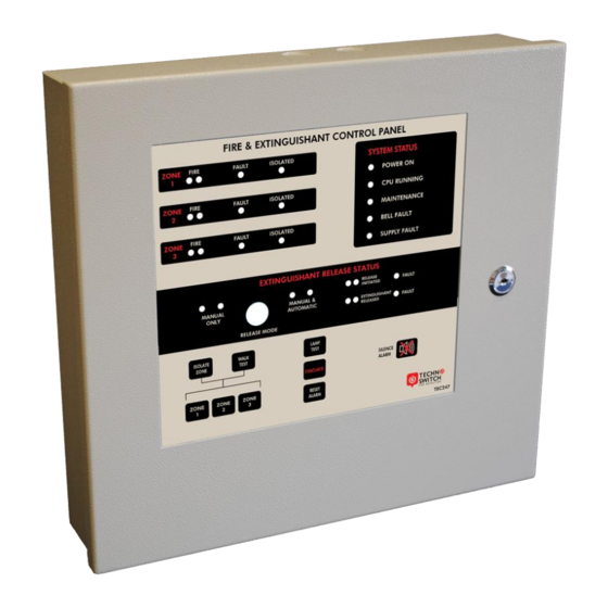
- Page 1 TEC247 Technoswitch Conventional Fire & Extinguishing Control Panel Rev 04.11 DOC NO. PRMAN-0003 TEC247 Rev 04.12 191209.docx Revised: 2019-12...
-
Page 2: Table Of Contents
TEC247 Fire & Extinguishant Control Panel – INSTALLATION & OPERATION MANUAL Contents SYSTEM DESCRIPTION ____________________________________________________ 2 SYSTEM COMPONENTS ___________________________________________________ 2 CONNECTION DIAGRAMS __________________________________________________ 3 POWER SUPPLY _________________________________________________________ 4 AC Mains Wiring _____________________________________________________________ 5 Battery Wiring _______________________________________________________________ 5 27.5 V DC Wiring ____________________________________________________________ 6... -
Page 3: System Description
TEC247 Fire & Extinguishant Control Panel – INSTALLATION & OPERATION MANUAL 1. SYSTEM DESCRIPTION A number of fire detection devices are wired into zones. The fire control panel monitors the circuits of these detection zones and will react on detecting either a Fire or a Fault condition within a zone. -
Page 4: Connection Diagrams
TEC247 Fire & Extinguishant Control Panel – INSTALLATION & OPERATION MANUAL 3. CONNECTION DIAGRAMS FIGURE 1 TEC247 – CONNECTION DIAGRAM DOC NO. PRMAN-0003 TEC247 Rev 04.12 191209.docx - 3 - E. &O.E. -
Page 5: Power Supply
TEC247 Fire & Extinguishant Control Panel – INSTALLATION & OPERATION MANUAL 4. POWER SUPPLY The internal power supply is a high efficiency switch-mode power supply with an input AC voltage range of 100-250 V AC. The power supply provides the following: ▪... -
Page 6: Ac Mains Wiring
TEC247 Fire & Extinguishant Control Panel – INSTALLATION & OPERATION MANUAL AC MAINS WIRING The high voltage AC mains wiring should be routed into the enclosure via a suitable knockout and kept away from any circuit boards and all other wiring. -
Page 7: Dc Wiring
TEC247 Fire & Extinguishant Control Panel – INSTALLATION & OPERATION MANUAL 27.5 V DC WIRING The motherboard of the control panel is supplied with 27.5 V DC from the power supply. In addition, the operating status of the power supply is communicated to the control panel via a communications lead. -
Page 8: Fault Relays/Outputs
TEC247 Fire & Extinguishant Control Panel – INSTALLATION & OPERATION MANUAL The Charger Fault LED will be solid on to indicate the charger is still off due to the additional current drawn on the output. The 24 V DC output remains active. -
Page 9: Hard And Soft Reset Function
TEC247 Fire & Extinguishant Control Panel – INSTALLATION & OPERATION MANUAL HARD AND SOFT RESET FUNCTION FIGURE 8 HARD AND SOFT RESET FUNCTION ▪ Hard Reset When a hardware reset power cycle is performed, the CPU as well as the 27.5 V DC output is shut down and restarted. -
Page 10: Manual Call Points
TEC247 Fire & Extinguishant Control Panel – INSTALLATION & OPERATION MANUAL MANUAL CALL POINTS Manual Call Points may be wired together with conventional detectors in a fire zone. The control panel requires an alarm resistance of 680 Ohms to be switched across the detection circuit to trip the fire zone into Alarm condition. -
Page 11: Extinguishant Release Detonator/Solenoid
TEC247 Fire & Extinguishant Control Panel – INSTALLATION & OPERATION MANUAL EXTINGUISHANT RELEASE DETONATOR/SOLENOID The discharge output provides 24 V DC 1 Amp output to activate solenoids and detonators. The duration of this output being active can be set on P12, 5 seconds or 5 minutes. -
Page 12: Door Switch
TEC247 Fire & Extinguishant Control Panel – INSTALLATION & OPERATION MANUAL 2. Only if the extinguishant control panel is switched to automatic release would these signals trigger the “Initiate” stage i.e. visual and audible warning and after the time delay (30 or 60 seconds), the extinguishant release stage i.e. - Page 13 TEC247 Fire & Extinguishant Control Panel – INSTALLATION & OPERATION MANUAL 20 minutes when the battery test automatically runs. Additional fault information is also available on the PSU PC Board that has individual LEDs for the following conditions MAINS FAIL, OVERLOAD, BATTERY FAULT, BATTERY LOAD FAIL, CHARGER FAIL and AC INPUT HIGH/LOW.
-
Page 14: Troubleshooting
TEC247 Fire & Extinguishant Control Panel – INSTALLATION & OPERATION MANUAL 7. TROUBLESHOOTING PROBLEM SOLUTION ▪ Remove zone wiring and replace the 3k3 in the affected zone and reset the panel. ▪ If the panel returns to normal operation there is a fault on the zone causing this condition and you should then proceed as follows: Measure the line resistance (should be ±3k3). -
Page 15: Techno Tip
TEC247 Fire & Extinguishant Control Panel – INSTALLATION & OPERATION MANUAL 8. TECHNO TIP All fire control panels have some outputs that must be monitored for open or short circuit fault. These outputs would typically operate devices like bells, sirens, beacons, detonators, solenoids or relay contacts. All these installations... -
Page 16: Technical Specifications
Sales Office for further information. 11. DISCLAIMER Although the contents of our product literature have been prepared with the greatest care, Technoswitch can accept no liability whatsoever for any direct or indirect damages of any kind that may arise due to either errors or omissions in them, or amendments to products or other specifications following publication. - Page 17 TEC247 Fire & Extinguishant Control Panel – INSTALLATION & OPERATION MANUAL NOTES DOC NO. PRMAN-0003 TEC247 Rev 04.12 191209.docx - 16 - E. &O.E.
- Page 18 TEC247 Fire & Extinguishant Control Panel – INSTALLATION & OPERATION MANUAL NOTES DOC NO. PRMAN-0003 TEC247 Rev 04.12 191209.docx - 17 - E. &O.E.
- Page 19 TEC247 Fire & Extinguishant Control Panel – INSTALLATION & OPERATION MANUAL NOTES DOC NO. PRMAN-0003 TEC247 Rev 04.12 191209.docx - 18 - E. &O.E.
- Page 20 TEC247 Fire & Extinguishant Control Panel – INSTALLATION & OPERATION MANUAL HEAD OFFICE — JOHANNESBURG +27 (0)11 794 9144 info@technoswitch.co.za Cussonia Park, 3 Ridge Road, Laser Park, Johannesburg PO Box 1752, Randpark Ridge, South Africa, 2156 CAPE TOWN +27 (0)21 948 4575 Tyger Terraces II, Block 2B, DJ Wood Street, Bellville Business Park Cnr Mike Pienaar Blvd &...
Need help?
Do you have a question about the TEC247 and is the answer not in the manual?
Questions and answers
Please can you help me with a wiring diagram for combination fire and extinguisher panel tech 247w