
Related Manuals for technoswitch TEC601


Summary of Contents for technoswitch TEC601
- Page 1 TEC601 3 Zone 19-inch Rack Extinguishing Control Panel Rev 04.01 DOC NO. PRMAN-0025 TEC601 Rev 04.01 210203.docx E&OE...
-
Page 2: Table Of Contents
TEC601 3 Zone 19” Rack Extinguishing Control Panel – INSTALLATION & OPERATION MANUAL TABLE OF CONTENTS SYSTEM DESCRIPTION _______________________________________________________________ 1 SUMMARY OF FEATURES _____________________________________________________________ 1 RECOMMENDED STAT-X UNIT PER SERVER CABINET SIZE ________________________________ 1 GENERAL ASSEMBLY ________________________________________________________________ 2 INDICATIONS & CONTROLS ___________________________________________________________ 3... -
Page 3: System Description
A power output for the equipment rack Air Handling Unit (AHU) is also provided to allow the TEC601 to shut down the air-handling unit just before the release of the extinguishant. -
Page 4: General Assembly
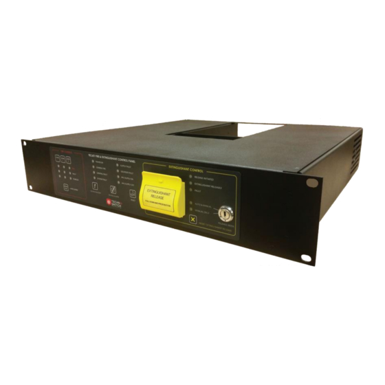
TEC601 3 Zone 19” Rack Extinguishing Control Panel – INSTALLATION & OPERATION MANUAL GENERAL ASSEMBLY FIGURE 1 TEC601 GENERAL ASSEMBLY FIGURE 2 TEC601 ENCLOSURE BACK VIEW FIGURE 3 ACCESS TO SMOKE DETECTORS FROM BOTTOM HATCHES PRMAN-0025 TEC601 Rev 04.01 210203.docx E&OE... -
Page 5: Indications & Controls
TEC601 3 Zone 19” Rack Extinguishing Control Panel – INSTALLATION & OPERATION MANUAL FIGURE 4 MINIMUM RECOMMENDED CLEARANCES INDICATIONS & CONTROLS Refer to FIGURE 1 and Table 1 & Table 2 for the location and description of panel indications and controls. -
Page 6: Indications
TEC601 3 Zone 19” Rack Extinguishing Control Panel – INSTALLATION & OPERATION MANUAL INDICATIONS Label Description Colour FIRE Indicates a fire per zone FAULT There is a fault on a zone Amber DISABLED The zone is disabled Amber POWER ON... -
Page 7: Quickstart / Installation
QUICKSTART / INSTALLATION Step 1 Unpack the TEC601 that includes: 1x TEC601 Extinguishing Panel, 1x Mains Cable, and 1x Key. Step 2 The unit is already connected to the internal battery and therefore it is not necessary to wire the internal batteries. -
Page 8: Operation In Auto & Manual Mode
During a discharge, the “EXTINGUISHANT RELEASED” LED will flash twice per second. After a discharge has taken place, the “EXTINGUISHANT RELEASED” LED will remain on. A manual reset on the TEC601 is required before the panel will be able to reset to Normal. OPERATION IN MANUAL ONLY MODE Manual release of the extinguishant is achieved by lifting the protector flap and pushing the “RELEASE... -
Page 9: Event Logging
TEC601 3 Zone 19” Rack Extinguishing Control Panel – INSTALLATION & OPERATION MANUAL Please check the EOL resistors on the sounder output and Zone 3 before finalising the commissioning. FIGURE 7 SOUNDER & 3 ZONE USING LINEAR HEAT CABLE EVENT LOGGING The events and conditions as listed in Table 3 below are logged and time stamped, provided that the RTC battery is maintained throughout the lifespan of the product. -
Page 10: Procedure For Extracting Logs
Plug the TEC601 into your computer. Make sure both the TEC601 and the computer are turned on before connecting them. During the driver installation, select “Have Disk” and browse to the “Technoswitch USB Driver.inf” file to complete the driver installation process. -
Page 11: Procedure For Setting The Date And Time
Plug the TEC601 into your computer. Make sure the TEC601 and the computer are turned on before connecting them. During the driver installation, select “Have Disk” and browse to the “Technoswitch USB Driver.inf”... -
Page 12: Service And Maintenance
TEC601 3 Zone 19” Rack Extinguishing Control Panel – INSTALLATION & OPERATION MANUAL 12. SERVICE AND MAINTENANCE 12.1 MAINTENANCE SCHEDULE This equipment should be maintained in accordance with the regulations and codes appropriate to the country and location of installation. The following is recommended if no other regulations apply. -
Page 13: Replacement Of Components
Connect the new Stat-X to the terminal plug. Push the wire back into the hole of the Stat-X mounting screw and tighten the new Stat-X firmly. Power on the TEC601 and ensure that there are no Fault conditions present. Ensure the panel is firmly mounted to the server cabinet and that the rear of the cabinet is closed. -
Page 14: Tec601 Technical Specifications
TEC601 3 Zone 19” Rack Extinguishing Control Panel – INSTALLATION & OPERATION MANUAL 13. TEC601 TECHNICAL SPECIFICATIONS Normal Operating Voltage 220 to 240 V AC Quiescent Current 50 mA AC Input Voltage Fuse 1.0 A DC Input Fuse Maximum Discharge Current Output Battery Backup 2x 1.2 Ah for 4 hour backup... -
Page 15: Generator Housing Clearance
Alternatively, please contact your local Sales Office for further information. 18. DISCLAIMER Although the contents of our product literature have been prepared with the greatest care, Technoswitch can accept no liability whatsoever for any direct or indirect damages of any kind that may arise due to either errors or omissions in them, or amendments to products or other specifications following publication. - Page 16 Tyger Terraces II, Block 2B, DJ Wood Street, Bellville Business Park Cnr Mike Pienaar Blvd & Voortrekker Road, Bellville, 7530 DURBAN +27 (0)31 266 8843 Colchester Building, Essex Gardens 1 Nelson Road, Westville 3629 www.technoswitch.co.za PRMAN-0025 TEC601 Rev 04.01 210203.docx E&OE...
Need help?
Do you have a question about the TEC601 and is the answer not in the manual?
Questions and answers