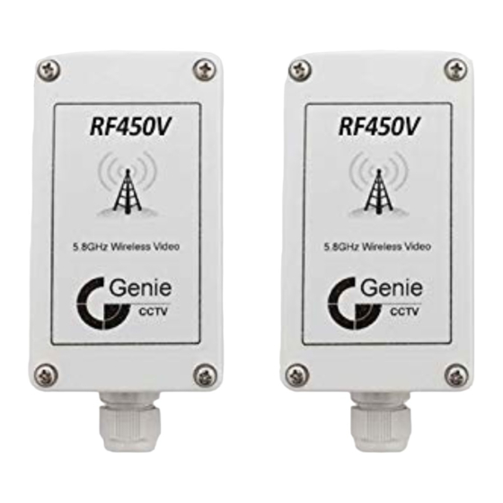
Summary of Contents for Genie RF450V
- Page 1 IP65 450m Analogue Wireless Video & Audio Link Pair RF450V User Manual Please read these instructions carefully before operating the unit and keep for further reference.
-
Page 2: Table Of Contents
Contents 1.0 Introduction ......................3 1.1 Product Features ...................4 1.2 Specification ....................4 2.0 Hardware ......................5 2.1 Transmitter and Receiver Hardware Layout ..........5 3.0 Programming .......................6 3.1 Transmitter Programming ................6 3.2 Receiver Programming ................6 4.0 Input and Tamper Connections ................8 4.1 Receiver ......................8 4.2 Transmitter ....................9 5.0 Receiver Signal / Status LED’s ................10... -
Page 3: Introduction
The Genie RF450V is a high quality 7 channel 5.8GHz audio / video wireless interface. Designed for the CCTV industry the RF450V is enclosed in a small IP65 rated enclosure, has a built in signal strength meter, status indicator, directional patch antennas and two digital inputs for an external input and a tamper circuit. -
Page 4: Product Features
User Manual IP65 450m Analogue Wireless Video & Audio Link Pair 1.1 Product Features • 5.8GHz • IP65 rated • 7 RF channels • 12 volt operation • High quality audio & video • 450m range (Line of site) • 7 LED signal strength meter (RSSI) •... -
Page 5: Hardware
2.0 Hardware 2.1 Transmitter and Receiver Hardware Layout Transmitter Receiever... -
Page 6: Programming
5. To save the current channel hold down the program switch for 3 seconds. If the two green LED’s flash twice a valid RF450V transmitter has been saved and paired, but if the two RED LED’s flash twice only the RF channel has been saved (no transmitter found). - Page 7 User Manual IP65 450m Analogue Wireless Video & Audio Link Pair 6. If “Program Timer” has been selected, the input LED flashes and the status LED’s indicate the selected option. To change the timer option briefly press the program key. The timer options are as follows: To save the new timer setting, hold down the program switch for 3 seconds.
-
Page 8: Input And Tamper Connections
4.0 Input and Tamper Connections 4.1 Receiver When the tamper circuit is healthy the output contacts are normally closed but under a fault condition the tamper contacts become open circuit. The tamper LED flashes when the receiver tamper switch is activated but if a tamper fault is detected with the transmitter, the tamper LED stays 100% illuminated. -
Page 9: Transmitter
User Manual IP65 450m Analogue Wireless Video & Audio Link Pair 4.2 Transmitter The tamper circuit is a normally closed circuit and is activated by a break. Typical wiring diagrams are shown below: The external input is a normally open circuit. To activate the input short circuit the input. Typical wiring diagrams are shown below:... -
Page 10: Receiver Signal / Status Led's
RF channel. To change the RF channel refer to the programming section. Briefly pressing the program switch again returns back the signal strength mode. If options 2 or 3 are left selected for more then 1 minute then the RF450V will default back to the signal strength mode. - Page 11 Sales +44(0)1707 330541 Enquiries sales@genieproducts.co.uk Website www.genieproducts.co.uk...


Need help?
Do you have a question about the RF450V and is the answer not in the manual?
Questions and answers