Carrier Alarko 6 Instruction Manual
Hide thumbs
Also See for Alarko 6:
- User's information manual (12 pages) ,
- Controls, start-up, operation, service, and troubleshooting (140 pages)

Related Manuals for Carrier Alarko 6


Summary of Contents for Carrier Alarko 6
- Page 1 DALGIÇ POMPALAR ve MOTORLARI 4”, 6”, 8”, 10”, 14” SUBMERSIBLE PUMPS and MOTORS Kullaným Kýlavuzu 6”, 7”, 8”, 10”, 14” INSTRUCTION MANUAL...
- Page 2 Booklet Revision Date: 261113 Booklet Printing Date: 261113 Revision No: D.1.1.8i...
- Page 3 DALGIÇ POMPALAR ve SUBMERSIBLE PUMPS MOTORLARI and MOTORS 4”, 6”, 8”, 10”, 14” 6”, 7”, 8”, 10”, 14” Kullaným Kýlavuzu INSTRUCTION MANUAL...
-
Page 5: Table Of Contents
CONTENTS Introduction ..................7 General Warnings ................8 Guarantee and Service..............9 Safety Precautions .................10 Model Code System ...............12 Main Parts ..................13 Main Parts - 6”, 7”, 8”, 10”, 14” Submersible Pumps....13 Technical Specifications .............15 Technical Specifications Table ............16 Dimensions .................17 Rotation Directions ..............17 Electrical Specifications, Dimensions, Weights ......18 Flow Rate- Manometric Height Curves........25 Standard Electric Control Panel............26... - Page 6 Submerssion Pump Into Well .............36 Electrical Circuit Installation ............38 Start-up Number .................38 Voltage Instability ................38 Commissioning ................39 First Checks ................39 Final Checks ................40 Maintenance ..................40 Long Term Non-Use ..............40 Checking the Electrical Values ...........41 Checking the Electrical Hardware ..........41 Malfunctions, Possible Reasons And Solutions ......42 EU Compatibility ................45...
-
Page 7: Introduction
You can seek further information on your submersible pump in product booklets or at ALARKO CARRIER’s authorized dealers. Keep this booklet for future reference. Following the commissioning, our authorized dealers and service agents will provide you with information on the use and maintenance of the pump. -
Page 8: General Warnings
GENERAL WARNINGS Do not touch any part or setting of your pump for reasons of running, adjusting or maintaining, except for the operations stated in this manual. The damages caused by the type of power cord you use with your pump and the nonconformities in the outage are evaluated outside the scope of the warranty. -
Page 9: Guarantee And Service
ALARKO CARRIER Cus- tomers Service Management. Keep your copy of this certificate in a safe place to produce it during any service work within the framework of the guarantee. -
Page 10: Safety Precautions
SAFETY PRECAUTIONS • A submersible pump group consists of a motor and a pump. A multi-step, vertical, and centrifugal pump is mechanically attached to an electric mo- tor operating in water. • In 6”, 7”, 8”, 10”, and 14” submersible pumps, pump rod has slide bea- rings. - Page 11 • Do not use the control panel to supply electricity to any other unit or ambience. • If the pump needs any repair and is to be sent to Alarko Carrier Authori- zed Service Agency, the control panel is to be sent as well.
-
Page 12: Model Code System
Seek advise from Alarko Carrier Authorized Dealers for all sorts of electric or mechanic problems and for the maintenance and repair of pump. The services undertake three functions in three steps: - First Step: Instalment of pump into well. - Second Step: Instalment of pump into well + Repair and maintenance of pump. -
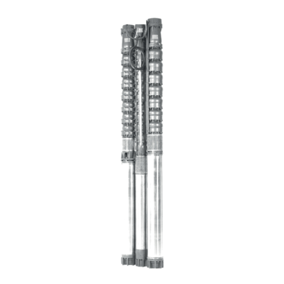
Page 13: Main Parts
MAIN PARTS 6”, 7”, 8”, 10”, 14” STANDART SUBMERSIBLE PUMPS 6”, 8” STAINLESI SUBMERSIBLE PUMPS... - Page 14 MAIN PARTS - 6”, 8”, 10” SUBMERSIBLE PUMP MOTORS TECHNICAL DATA - 6”, 8”, 10”, 14” Submersible Pump Motors Technical Specifications Three types of submersible motors are available to operate 6", 8", 10", 14" submersible pumps: AL6, AL8, and AL10. All water lubricated submersible pump motors with a capacity range of 4-180 HP are three-phase, asynchronous, and squirrel cage.
-
Page 15: Technical Specifications
TECHNICAL DATA - 6”, 8”, 10” SUBMERSIBLE PUMP MOTORS Technical Specifications Three types of submersible motors are available to operate 6”, 8”, 10” submersible pumps: AL6, AL8, and AL10. All water lubricated submer- sible pump motors with a capacity range of 4-180 HP are three-phase, asynchronous, and squirrel cage. -
Page 16: Technical Specifications Table
6011/5+A L4-3 1053 26,5 6011/6+A L6-4 1118 6011/10+AL6-6 11,5 1297 6011/12+AL6-7,5 13,2 1403 Pipe Thread 6011/16+AL6-10 17,8 1588 ISO 228-G2 AL6” ECO Technical Specifications Table 6011/24+AL6-15 26,4 1968 6011/30+AL6-20 34,6 2308 Axial Motor Motor Motor Weight 6011/36+AL6-25 42,7 2653 MOTOR Load Length Rate... -
Page 17: Dimensions
TECHNICAL DATA - 6”, 8”, 10”, 14” Submersible Pump Motors Dimensions Dimensions TECHNICAL DATA - 6”, 8”, 10”, 14” Submersible Pump Motors AL10 Dimensions AL10 A Cross-Section A Cross-Section A Cross-Section A Cross-Section A Cross-Section A Cross-Section MOTOR ROTATION DIRECTION MOTOR ROTATION DIRECTION Normal Rotation Counter Rotation... -
Page 18: Electrical Specifications, Dimensions, Weights
TECHNICAL DATA - 6”, 7”, 8” SUBMERSIBLE PUMPS Electrical Specifications, Dimensions and Weights TECNICAL DATA - 6”, 8”, 10”, 14” Submersible Pumps Flow Rate - Manometric Height Curves Rated Rated Outher Pump+Motor TYPE Weight Discharge Diameter of Power Current Length (mm) Pump+Motor (kg) Diameter... - Page 19 values has to remain between toleration limits of -10% and 6%. If these limits are exceeded or higher voltages or longer cables are needed, do not use the following tables. INSTALLATION ELEMENTS Electrical Specifications, Dimensions and Weights For mono-phase 220 V motors: Electric Cable Cross-Section and Length Nom inal Motor Rate...
- Page 20 1. Check the well water temperature and grit content of water in a laboratory. 2. Pipe and pipe rings have to be strong enough to carry the pump group, water in the vertical pipe, and its own weight. Check the resistance of pipes. 3.
- Page 21 TECHNICAL DATA - 6”, 7”, 8” SUBMERSIBLE PUMPS Electrical Specifications, Dimensions and Weights INSTALLATION OF PUMP INTO A WELL TYPE Pump+Motor General Principles 1. Check the well water temperature and grit content of water in a laboratory. 2. Pipe and pipe rings have to be strong enough to carry the pump group, water in Pipe Thread the vertical pipe, and its own weight.
- Page 22 Rated Rated Pump+Motor Outher TYPE Weight Diameter of Power Current Length (mm) Pump+Motor Pomp Body (HP) (mm) Pipe Thread Rated Pump+Motor Outher Rated Current TYPE Discharge Diameter of Power Length Weight Pump+Motor Pomp Body Diameter (HP) (mm) (mm) Pipe Thread Rated Rated Discharge...
- Page 23 TECHNICAL DATA - 10”, 14” SUBMERSIBLE PUMPS Electrical Specifications, Dimensions and Weights TYPE Rated Rated Discharge Pump+Motor Outher Weight Diameter of Length INSTALLATION OF PUMP INTO A WELL Power Current Diameter Pump+Motor Pomp Body (mm) (HP) (mm) Installation into an average well Pipe Thread Manometer Manometer...
- Page 24 TECNICAL DATA - 6”, 8” STAINLESS STEEL SUBMERSIBLE PUMPS Flow Rate - Manometric Height Curves Rated Discharge Rated TYPE Power Pump+Motor Outher Weight Diameter of Current Diameter Length Pump+Motor Pomp Body (mm) (mm)
-
Page 25: Flow Rate- Manometric Height Curves
Flow Rate - Manometric Height Curves... -
Page 26: Standard Electric Control Panel
STANDART ELEKTRIC CONTROL PANEL Standard Electric control panel has the following elements: 1. Electric Control LED: Displays electricity supply and failure of supply. 2. Main Switch: Opens and shuts electric supply to the panel. 3. Control Switch: Starts up motor. 4. -
Page 27: Installation Elements
INSTALLATION ELEMENTS Hydrolic Circuit Elements • Check-valve: There is a check-valve in the vent body which is in the upper part of the pump. (See. Diagrams for the installation of pump into well on page …). • Valve: There must be a valve on the discharge pipe to adjust flow rate. Continuous operation of pump when the valve is open or without any valve, or operation of pump for more than five minutes when the valve is closed reduces the life of pump and/or motor (See. -
Page 28: Electric Cable Cross-Section And Length
Never use wires. Well water level Ensure the level of might have been water is high fallen. Check. Is it enough for the law? pump to start. There may be a mechanical problem in pump. Please call Alarko Carrier Authorized Service. -
Page 29: Installation Of Pump Into A Well
INSTALLATION OF PUMP INTO A WELL General Principles 1. Check the well water temperature and grit content of water in a labo- ratory. INSTALLATION OF PUMP INTO A WELL 2. Pipe and pipe rings have to be strong enough to carry the pump group, water in the vertical pipe, and its own weight. -
Page 30: Installation Into A Wide Well 1
GENERAL SELECTION NOMOGRAM – 6”, 7”, 8”, 10”, 14” INSTALLATION OF PUMP INTO A WELL SUBMERSIBLE PUMPS Flow Rate – Manometric Height Curves Installation into a Wide Well 1 Installation into a Wide Well 1 Manometer Manometre There may be a resistance of 2Ω... -
Page 31: Installation Into A Wide Well 2
INSTALLATION OF PUMP INTO A WELL Installation into a Wide Well 2 Installation into a Wide Well 2 Ventillation Inlet cap Cap plate Manometer connection Valve Carrier profiles Clamp Discharge pipe Energy cable of Immersion type Cable clamp Check-valve Pump... -
Page 32: Installation Into An Average Well
Installation into an average well Check Valve: There is a check valve on the vent body which is in the upper part of the pump. It is recommended that an external check valve is used on the pumping pipe next to the well, between the pump and the valve, and repeat this every 200 meters in long pumping lines. -
Page 33: Mounting Information And Instructions
1. Check the electric supply cable to ensure that it is intact without any damages. If it is damaged, it has to be replaced by Alarko Carrier Aut- horized Dealers. -
Page 34: Charging Water Into Motor
network in terms of voltage, number of phase, current, and frequency. If the values do not match, wait until the proper energy values are supplied before starting the motor. 5. Note: It is recommended that an external check valve is used on the pumping pipe next to the well, between the pump and the valve. - Page 35 If you need to add anti-freeze and water mixture into motor: 1. Charge motor with the mixture with a water filler (Figure 3). The content of the mixture is explained below. 2. Wait for 30 minutes before taking the water filler out. By this time any air bubbles will be dispelled.
-
Page 36: Submerssion Pump Into Well
For further information on installation, refer to “Drawings of Installation in the Well”. 1- Secure a carrier bracket below the coupling at the upper part of the 0.5-meter short riser. 2- Secure the riser to the forcing port of the pump with a screw. - Page 37 5- In water charged star-delta start-up motors, measure the insulation of each duct by making one end of the Meger Unit touch each of the multi- duct two electricity cables and the other end touch the pump casing. - The duct with an insulation value of 0 mega ohm is the frame conductor.
-
Page 38: Electrical Circuit Installation
12. Lift the pump group a bit with the help of the second clamp and tigh- ten the first clamp. Descend the pump group into the well so that the second clamp is suspended in the well opening. 13. Continue the same operation until the pump is in desired depth. 14. -
Page 39: Commissioning
5%. COMMISSIONING First Checks ! Alarko Carrier authorized Services are authorized for conducting the commissioning operations. 1- Measure the grid voltage. -The deviation of the measured value for all three phases must remain inside -10%, +6% tolerances. -
Page 40: Final Checks
- If this value is not below 2 megaohms, pump operation can continue safely. - If the measured value is below 2 megaohms, Alarko Carrier Authorized Service must be informed. - Isolation check must be performed each month. -
Page 41: Checking The Electrical Values
Checking the Electrical Values When the pump is commissioned, the current, voltage and pressure valu- es at the running point must be recorded and it should be observed if there is any change in these values in time. Checking the Electrical Hardware - Electrical hardware (including the panel) must be checked every six months. -
Page 42: Malfunctions, Possible Reasons And Solutions
Check the fuses. Replace the fuses, Are they blown? never use a wire. Maket he well water level rise enough tol et the pump run. There might be a mecha- nical malfunction on the pump Please call Alarko Carrier Authorized Service... - Page 43 For direct startup mo- tors, set the thermal settigs to the ampere Please call Alarko value on the motor Carrier Authorized label. Service. For star / delta startup motors, set the thermal setting to motor label ampere value x 0,58 =...
- Page 44 Is it low? pump deeper as long as the well conditions are suitable. Decrease the flow rate throttling down the valve. Do the movements on ammeter continue? Do not run the pump. Please call Alarko Carrier Authorized Service.
- Page 46 (0322) 457 62 23 - Fax: (0322) 453 05 84 ANTALYA : Metin Kasapoğlu Cad. Küçükkaya Sitesi A Blok No: 1 D. 4, ANTALYA web: www.alarko-carrier.com.tr Tel: (0242) 322 00 29 - Fax: (0242) 322 87 66 e-posta: info@alarko-carrier.com.tr : 444 0 128...
Need help?
Do you have a question about the Alarko 6 and is the answer not in the manual?
Questions and answers