Table of Contents
Advertisement
Available languages
Available languages
Quick Links
ENG | Instruction Manual
LK 950 P Valve Actuator
TECHNICAL DATA
Power supply
Control signal/Position signal
Dimensioning
Power consumption
Connection
Direction of operation
Manual override
Torque
Angle of rotation
Running time*
Sound level
Position indication
Mounting position
Accessories*
Protection type
Protection class
Ambient temperature
Storage temperature
Safety
* = Depending on model
FUNCTIONAL DESCRIPTION
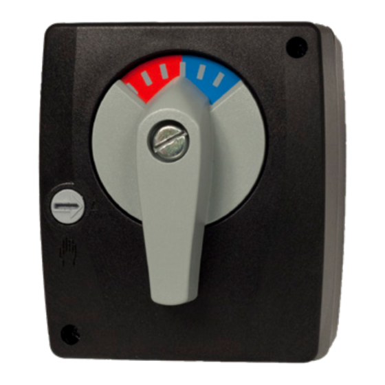
LK 950 is a series of compact actuators designed to motorize rotary
mixing valves. The actuator is controlled by means of a modulating
signal 2 (0)-10 VDC. LK 950 fits most rotary valves. Alternative moun-
ting kits can be supplied as option.
OPERATION
The actuator can be mounted in any position except below the
valve. Thanks to its small size and compact form the LK 950 fits
most installations.
The actuator is mounted directly onto the valve spindle with a screw. An
anti-rotation bolt is screwed
onto the valve. The angle of rotation is limited to 90°. When the actuator
reaches either end position the voltage supply is interrupted by limit
switches. The actuator can be put into manual mode by turning the but-
ton on the housing cover which will disengage the gears. The actuator
can now be put in any position by turning the handle on the front and
this position is indicated by means of a reversible scale.
MOUNTING INSTRUCTION
1.
Turn the spindle of the valve A counter clockwise to the end posi-
tion (OPEN or CLOSED). Remove the handle supplied with the valve
body from the valve spindle.
2.
Screw the anti-rotation stop B in a convenient hole on the valve (if
necessary remove an existing screw).
3.
Slide the linkage C over the valve spindle.
4.
Place the actuator D onto the linkage C and if necessary rotate it
slightly clockwise until the antirotation stop B engages in the slot of
the actuator (the actuator is supplied in the anti-clockwise position).
5.
Turn the scale E into the position relevant to the
1
24 VDC/VAC 50/60 Hz
2 (0) - 10 VDC, max 0,5 mA
3 VA
1.5 W
Terminal block
Selectable
Disengagement of gears
5 Nm
90°, electrically limited
35 / 70 s
Max. 35 dB(A)
Reversible scale
Selectable except below the valve
Alternative mounting kits
IP 40
III (SELV)
0 ... 50 °C
-10 °C ... 80 °C
CE (see Declaration of Conformity)
quested function (OPEN/ CLOSED) and place it onto the actuator.
6.
Place the handle F onto the actuator ensuring that
the arrow points to the left end position of the scale.Tighten the
whole unit by means of the screw G.
7.
Using a screwdriver (No. 3) turn the disengaging button on the
housing cover from «A» to «Hand Symbol» position and rotate the
valve by means of the handle F from one end position to the other.
It is important that the actuator can be moved from one end stop
to the other (90°).
8.
Connect the actuator to the power supply.
9.
Turn the disengaging button back to the«A» position and the
actuator will turn in the required position.
WIRING DIAGRAM
24 VAC
24 VDC
-
1 2
LK 950 Proportional
LK 950 proportionell
re-
A
B
www.lkarmatur.com
Control signal
Styrsignal från regulator
Position feedback
Utsignal för lägesindikering
GND
GND
~
Y
U
+
All applicable legal or institutional
3
5
installation regulations must be
complied with.
Brytare 1
Gångriktning
Moturs *)
Medurs
Brytare 1
Brytare 2
Arbetsområde
2 - 10 VDC *)
0 - 10 VDC
Brytare 1
Gångriktning
Brytare 2
Moturs *)
*) Fabriksinställning
Medurs
Brytare 1
Brytare 2
Switch 1 Direction of rotation
Arbetsområde
2 - 10 VDC *)
Counterclockwise *)
0 - 10 VDC
Brytare 2
*) Fabriksinställning
Switch 1
Direction of rotation
Clockwise
Brytare 1
Gångriktning
Counter-clockwise *)
Moturs *)
Clockwise
Medurs
Switch 2 Operating range
Switch 1
Brytare 1
Switch 2
Operating range
Brytare 2
Arbetsområde
2-10 VDC *)
2 - 10 VDC *)
Switch 2
0 - 10 VDC
Brytare 2
0-10 VDC
*) Fabriksinställning
Factory setting
*) Factory setting
C
D
E
]
0-10 VDC
2-10 VDC
F
G
Advertisement
Table of Contents

Related Manuals for LK Armatur LK 950 P


Summary of Contents for LK Armatur LK 950 P
- Page 1 ENG | Instruction Manual LK 950 P Valve Actuator TECHNICAL DATA Power supply 24 VDC/VAC 50/60 Hz Control signal/Position signal 2 (0) - 10 VDC, max 0,5 mA quested function (OPEN/ CLOSED) and place it onto the actuator. Dimensioning 3 VA...
- Page 2 DE | Bedienungsanleitung Schraube G festziehen. TECHNISCHE DATEN Mit Schraubendreher (Nr. 3) den Handverstellknopf am Antrieb von Speisespannung 24 VDC/VAC 50/60 Hz «A» auf «» stellen und mittels Handgriff F den Mischer von einer End- Stellsignal/Stellungs- 2 (0) - 10 VDC, max 0,5 mA stellung in die andere drehen.
- Page 3 FR | Manuel d’instruction graduation sur le cadran. Ensuite, fixer l’ensemble au moyen de la DONNÉS TECHNIQUES vis G Tension d’alimentation 24 VDC/VAC 50/60 Hz A l’aide d’un tourne-vis (No. 3) tourner le bouton de débrayage sur le Commande régulateur/ 2 (0) - 10 VDC, max 0,5 mA servomoteur de la position «A»...
- Page 4 IT | Manuale di istruzioni desiderata (valvola APERTA / CHIUSA). DATI TECNICI Inserire la manopola F assicurandosi che la freccia sia ruotata Tensione nominale 24 VDC/VAC 50/60 Hz verso sinistra (direzione antioraria). Fissare la manopola con la vite G. Segnale in ingresso / 2 (0) - 10 VDC, max 0,5 mA Con un cacciavite ruotare il pulsante di disinnesto del motore Segnale in uscita...
- Page 5 FI | Asennus- ja käyttöohje tuspainiketta asennosta «A » käsikäyttö asentoon. Kääntä- TEKNISET TIEDOT mällä toimilaitetta kahvasta F varmistat, että venttiili kääntyy Nimellisjännite 24 VDC/VAC 50/60 Hz 90 ast. Ohjaus-/Takaisin- 2 (0) - 10 VDC, max 0,5 mA Kytke toimilaite virtapiiriin. kytkentäviesti Käännä...
- Page 6 SE | Instruktionsmanual till det andra. Det är viktigt att motoraxeln kan vridas hela TEKNISKA DATA vägen mellan ändlägena. Matningsspänning 24 VDC/VAC 50/60 Hz Anslut matningsspänningen. Styrsignal / Utsignal 2 (0) - 10 VDC, max 0,5 mA Vrid tillbaka frikopplingsskruven till läge ”A”. Dimensionering 3 VA Motorn kan nu vrida ventilen till önskat läge.
- Page 7 ENG | DE | FR | IT | FI | SE SPARE PARTS | ERSATZTEILE | PIÈCES DE RECHANGE | RICAMBI | VARAOSAT | RESERVDELAR Part No. | Teil Nr. | Pièce No | Art. no. | Art. Nr. | No de réf. | Article | Artikel | Article | Articolo | Nimike | Artikel Ogetto No | Osa nr.
- Page 8 LK ARMATUR AB www.lkarmatur.com LK ARMATUR DEUTSCHLAND GMBH www.lkarmatur.de...
Need help?
Do you have a question about the LK 950 P and is the answer not in the manual?
Questions and answers