Table of Contents
Advertisement
Advertisement
Table of Contents

Subscribe to Our Youtube Channel
Related Manuals for Logiquip Dri-Stor


Summary of Contents for Logiquip Dri-Stor
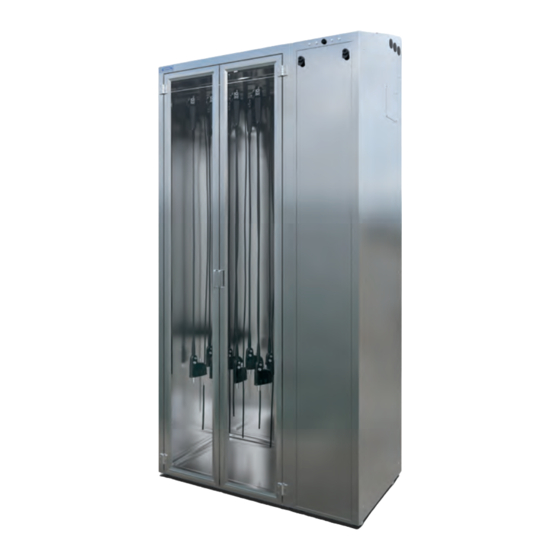
- Page 1 INSTALLATION & USER GUIDE Dri-Stor INSTALLATION GUIDE Read and understand all of the instructions and safety CAUTION information in this document before operating this product. SAVE THESE INSTRUCTIONS (800) 665-3760 www.logiquip.com customersupport@logiquip.net...
-
Page 2: Table Of Contents
Uncrating Instructions ........12 Transporting Dri-Stor Cabinets ....... . 13 Confirm Receipt Of Order Contents . - Page 3 Remove All Users & Scopes ....... . 33-34 TROUBLESHOOTING 35-38 WARRANTY www.logiquip.com...
-
Page 4: Introduction
INTENDED USE LogiQuip Dri-Stor Cabinets are designed to ensure a clean storage location for disinfected Endoscopes and Probes while protecting them from damage while in storage. Configurations within the product family may also provide added functionality such as moisture control, scope tracking, and other security features. -
Page 5: Safety Precautions
2. Use the troubleshooting information on pages 35-38 to determine what is causing the issue. 3. If it is not possible to identify or eliminate the cause using this document, switch the device off and call LogiQuip Customer Support at (800) 665-3760. www.logiquip.com... - Page 6 Do not replace or use Mains cords with inadequately rated supply. Use only cables labeled for applicable voltage or voltage range, frequency or frequency range, and/or power or current RATING when stated on the label by LogiQuip, and install in the order of the instructions shown.
-
Page 7: Product Specifications
Models of product may be able to be functionally upgraded to a different standard of configuration. (Ex. to add tracking functionality or scope capacity. ) Contact LogiQuip for information on applicability. Where configuration and installed features may have been tailored alongside customer input, contact LogiQuip Customer Service with questions unique to a specific unit. -
Page 8: Optional Features & Accessories
OPTIONAL FEATURES & ACCESSORIES OPTIONAL FEATURES & ACCESSORIES KEYPAD SECURITY LOCK This security feature allows restricted access to personnel that have a unique 4-digit code, for up to a maximum of 50 unique codes. The Keypad is configurable to add/remove codes as required by the user. -
Page 9: Ultrasound Probe Holders
The transducer connector fits into the custom holder, while the transducer cable wraps around the strain relief hanger. The probe hangs from the top hook, through the slotted acrylic cylinder, and through the bottom hook with an acrylic cylinder to protect the distal end of the probe. www.logiquip.com... -
Page 10: Pre-Installation Instructions
PRE-INSTALLATION INSTRUCTIONS SITE PREPARATION Prior to order confirmation, please discuss requirements for installation with your LogiQuip Sales Representative. Discuss all pre-installation information with your Sales Representative. Follow Local Guidelines & Codes. The height of the GFCI outlet should follow any local code requirements as well as facility guidelines. -
Page 11: Tools Required
Avoid injury from falling crate panel when removing screws. Two people are required for uncrating the unit. One person must secure the crate panel while the second person is removing the screws. WARNING: POSSIBLE EQUIPMENT DAMAGE Avoid damage to the unit. Secure the center support. Do not allow the center support to fall on the unit. www.logiquip.com... -
Page 12: Uncrating Instructions & Transportation
UNCRATING INSTRUCTIONS UNCRATING INSTRUCTIONS The Endoscope Cabinet will typically be shipped in a wooden crate. If so, follow all instructions below to remove the wooden crating material, otherwise skip to Step 6: Remove Packaging. 1. Using a fork lift or pallet jack, transport the unit to a level floor near the installation site (Fig.1). 2. -
Page 13: Transporting Dri-Stor Cabinets
UNCRATING INSTRUCTIONS TRANSPORTING DRI-STOR CABINET(S) WARNING: PERSONAL INJURY It is recommended to use a furniture dolly (or similar) to easily transport the Cabinet(s) to their destination. 1. Once the doors are secured, place both dollies next to the crate, one (1) dolly on each end of the cabinet. Slide the Cabinet over to the Dollies from the crate. -
Page 14: Confirm Receipt Of Order Contents
UNCRATING INSTRUCTIONS CONFIRM RECEIPT OF ORDER CONTENTS Prior to installation, ensure that you have the following standard packaging contents for your model, in addition to any acces- sories or expected options which are indicated by your ordering details. MODEL CONTENTS •... -
Page 15: Initial Set-Up
¾ screw, lock washer, and washer into the six (6) side panel holes loosely, these will be secured firmly in a following step (Fig. 6). Fig. 6 5. Connect the power cord to the upper rear of the component Cabinet. www.logiquip.com... -
Page 16: Placing & Preparing Top-Load Cabinets
INITIAL SET-UP INITIAL SET-UP (CONTINUED) PLACING & PREPARING TOP-LOAD CABINET(S) This section applies to all Top Load models. 1. Using a Phillips head screwdriver, remove the locking top panel of the component compartment for access to the serviceable area. Set aside panel in a location which does not create a hazard. 2. -
Page 17: Installation
Fig. 11 Fig. 13 Fig. 14 Light Bar installation for Tracking (V1) Cabinets is completed within instruction for Electrical Plate and CPU Installation. Light Bar installation for Tracking (V2) Cabinets is completed within instruction for Major Control Box Installation. www.logiquip.com... -
Page 18: Control System Components
Do not replace or use Mains cords with inadequately rated supply. Use only cables labeled for applicable voltage or voltage range, frequency or frequency range, and/or power or current RATING when stated on the label by LogiQuip, and install in the order of the instructions shown. -
Page 19: Channel Purge Pumps
Pumps (Fig. 17), and then connect the Tubing to the Connect in-Line HEPA filter. Secure the connection using a butterfly clip (Fig. 18). Barb Tee Connector 9. Repeat Steps for each Channel Purge Pump included in your ordered configuration. Butterfly Clips ¼” Tubing www.logiquip.com Labels Fig. 19... -
Page 20: Electrical Plate & Cpu
INSTALLATION INSTALLATION OF CONTROL SYSTEM COMPONENTS (CONTINUED) INSTALL ELECTRICAL PLATE & CPU 1. Plug three-prong 120V power supply from control manifold into power strip (Fig. 20) located in component compartment. 2. Connect door lock cable (L1) to control manifold (L1). If Add-On storage Cabinet is present, connect door lock cable (L2) to control manifold (L2). -
Page 21: Connecting Channel Purge & Endotrack
1. Plug pump power cord into Pump 1 outlet on control manifold (Fig 21). Repeat steps 2 to 4 for channel Channel Purge pumps (if applicable). 2. Please see Dri-Stor Tubing Set for more information. CONNECT ENDOTRACK TOUCHSCREEN TO ELECTRICAL Fig. -
Page 22: Apc Battery Back-Up Set-Up
INSTALLATION APC BATTERY BACK-UP SET UP The APC Battery Back-Up will be referred to as a UPS (Uninterruptible Power Supply) 1. Open the battery compartment by pressing the tab and sliding the cover out (Fig. 23). 2. Remove the yellow instructions tape attached and pull out the battery halfway from the UPS to access the battery terminal connections (Fig. -
Page 23: Major Control Box
8. Connect the USB cables (labeled GPIO32 and Relay8) to the USB ports on the front of the control box. 9. If present, connect the Add-On Cabinet sensor cables labeled: L2, F2, and D2 to the respective ports as well. Fig. 28 Fig. 29 www.logiquip.com... -
Page 24: Connecting Channel Purge, Cpu & Touchscreen
INSTALLATION MAJOR CONTROL BOX INSTALLATION (CONTINUED) CONNECT CHANNEL PURGE PUMP(S) TO MAJOR CONTROL BOX 1. Plug pump power cord(s) respective to the Main Cabinet into PL1 (and PL2 if applicable) outlet(s) on the Major control box. Where an Add-On Cabinet is present, plug pump power cord(s) into PR1 (and PR2 if applicable) as well. CONNECTING CPU &... -
Page 25: Hepa Channel Purge Control Box
4. Plug Cabinet power into prepared electrical outlet. Fig. 39 Fig. 36 Fig. 37 Fig. 38 Your Cabinet is now ready to be turned on. Next you must perform a Test of Component Functions, to ensure all components are operational. www.logiquip.com... -
Page 26: Test Component Functions
INSTALLATION TEST OF COMPONENT FUNCTIONS COMPONENT AND LEVELING TEST 1. Check door operation by opening and closing doors completely, verifying smooth operation. 2. Verify door hinges are secure and are not hindering door operation. 3. Verify Cabinet sits level and Cabinet doors sit flush with Cabinet. 4. -
Page 27: Endotrack Set-Up
1. From the Main Screen, press the Logo located on the Top Left of the screen. 2. Enter the Access Code to access the Supervisor page (Fig. 40). 3. Adjust the Date and Time as required (Fig. 41) on the Settings Tab. 4. Press Save. Fig. 40 Fig. 41 www.logiquip.com... -
Page 28: Cabinet Configuration
ENDOTRACK SET-UP CONFIGURE ENDOTRACK TRACKING SOFTWARE SETTINGS (CONTINUED) CABINET CONFIGURATION SETTINGS Set up Cabinet to Required Configuration (Fig. 42) 1. Press the Logo Icon located on the Top Right of the screen, and then enter the Service Page access code. 2. -
Page 29: Set/Reset Hepa & Pre-Filter Timers
5. Enter the users name under “Name” by using the keypad on the screen and then press Enter (Fig. 46). 6. The newly added User will appear on the list. Fig. 44 Repeat steps 1-5 to add more users. Fig. 45 Fig. 46 www.logiquip.com... -
Page 30: Manually Add A New Scope
ENDOTRACK SET-UP CONFIGURE ENDOTRACK TRACKING SOFTWARE SETTINGS (CONTINUED) MANUALLY ADD NEW SCOPE 1. To add new scopes, press the Scopes Tab to begin (Fig. 47). 2. Press the “Add New” button on the right side of the screen. 3. Enter Scope ID under “ID” by using the keypad on the screen (Fig. -
Page 31: Import User & Scope List
4. Enter each Scope ID and Scope Model on a new line using the following format “ScopeModel,ScopeID”. Ensure that there are no spaces after the comma. 5. Exit the text editor and save any changes made. Fig. 54 Fig. 53 www.logiquip.com... -
Page 32: Create User File
ENDOTRACK SET-UP CONFIGURE ENDOTRACK TRACKING SOFTWARE SETTINGS (CONTINUED) CREATING A USER LIST FILE FROM SCRATCH 1. Create a new text file using a text editor such as Notepad (Windows) or TextEdit (Mac) (Fig. 55). 2. Save the file as “Scope.csv” (without quotations) (Fig. 56). 3. -
Page 33: Remove All Users & Scopes
1. From the Main Screen, press the Logo Icon located on the Top Left of the screen. 2. Enter the Access Code to access the Supervisor page. 3. Press the Scopes Tab and then press the ‘Remove All’ button (Fig. 63). 4. Press Remove All to remove all scopes (Fig. 64). Fig. 64 Fig. 63 www.logiquip.com... - Page 34 A confirmation box will appear if the “Remove All” button has been pressed accidentally. Fig. 65 Fig. 66 WARNING: Prior to Using Your Drying Cabinet you MUST CLEAN AND SANITIZE. Please refer to the Dri-Stor Use & Care Guide pages14-18 for detailed cleaning instructions. (800) 665-3760...
-
Page 35: Troubleshooting
Entire Cabinet is leaning forward or backward Leveling tool shows Cabinet is leaning forward or backward • Move doors apart by adjusting one or more door hinges. Doors are rubbing against each other when opening or closing the door Start with middle hinge first. www.logiquip.com... - Page 36 (CONTINUED) TROUBLESHOOTING HEPA CABINET LED LIGHT NOTIFICATIONS Users/supervisors may use the following information and steps within the scope of approved/operating instructions only. Contact LogiQuip Customer Support prior to action outside the scope of operating instruction in all cases. INTENDED NOTIFICATION...
- Page 37 TROUBLESHOOTING HEPA CABINET LED LIGHT NOTIFICATIONS (CONTINUED) Users/supervisors may use the following information and steps within the scope of approved/operating instructions only. Contact LogiQuip Customer Support prior to action outside the scope of operating instruction in all cases. INTENDED NOTIFICATION...
- Page 38 TROUBLESHOOTING HEPA CABINET LED LIGHT NOTIFICATIONS (CONTINUED) Users/supervisors may use the following information and steps within the scope of approved/operating instructions only. Contact LogiQuip Customer Support prior to action outside the scope of operating instruction in all cases. INTENDED NOTIFICATION...
-
Page 39: Warranty
Electronic components, Cart Covers, Custom Products, LogiCell Tambour Doors, Label Holders, and Casters. During this period, LogiQuip will, in its sole discretion, repair defects in materials or workmanship that existed when the product was received or replace the product. Visit LogiQuip com/Warranty for more details.
Need help?
Do you have a question about the Dri-Stor and is the answer not in the manual?
Questions and answers