Table of Contents
Advertisement
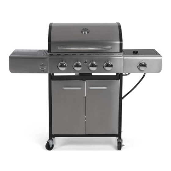
Enjoy Your
USE AND CARE GUIDE
E02GR001
This appliance is for Household use only.
This is not a commercial appliance.
Questions, problems, missing parts? Before returning to the store,
please contact our Customer Service
service@alphamarts.com
THANK YOU
inually create
quality products designed to enhance your home. Visit us online to see our full line of products available for your home improvement needs.
Thank you for choosing Captiva Desings!
Advertisement
Table of Contents

Subscribe to Our Youtube Channel
Related Manuals for Captiva Designs E02GR001


Summary of Contents for Captiva Designs E02GR001
- Page 1 Enjoy Your USE AND CARE GUIDE E02GR001 This appliance is for Household use only. This is not a commercial appliance. Questions, problems, missing parts? Before returning to the store, please contact our Customer Service service@alphamarts.com THANK YOU inually create quality products designed to enhance your home. Visit us online to see our full line of products available for your home improvement needs.
-
Page 2: Table Of Contents
Table of Contents Warnings LP Gas Cylinders 18-19 Troubleshooting Components & Hardware Lists First-Time Operation 21-22 Preparation Care and Maintenance 23-24 Assembly Instructions 9-16 Gas Leaks Warranty Safety Information Assembler/Installer This instruction manual contains important information necessary for the proper assembly and safe use of this appliance. - Page 3 Built from lasting materials and designed to withstand unreasonably harsh testing, this powerful grill outperforms its weight class. For our customers, our clients, our friends, our lifelong partners becoming true cookout champions on a Captiva Designs gas grill means proudly joining the family. There’s always room around our table for one more.
-
Page 4: Warnings
IMPORTANT SAFETY Please read this manual carefully and before installing or using your Captiva Designs gas grill to ensure proper operation, installation, and servicing, and to reduce the risk of re, burn hazard, and/or other injury. This manual should be retained for your information. - Page 5 Never use charcoal or any other solid fuel in the grill. PROPER USE This Captiva Designs grill in NOT intended for commercial use. Do not operate the grill in a building, garage, or any other enclosed areas. This could result in carbon monoxide buildup, which may cause injury or death.
- Page 6 Warnings For proper operation, burners must be aligned with the valve ori ce and seated in the bracket slot. This is accomplished by rst placing the burner tube’s shutter hole securely over the valve ori ce, and ensuring the male post on the rear of the burner rests in the opening in the grill chassis. Failure to do so could result in a re and/or injury.
- Page 7 Warnings GENERAL WARNINGS All gas grills get hot during use. Use extreme caution when operating. Do not touch hot surfaces. Always use the lid handle to open or close the grill. Use cooking utensils with wood handles and insulated oven mitts when operating the grill. Never lean over the cooking surface when lighting or operating the grill.
-
Page 8: Components & Hardware Lists
Package Contents Quantity Quantity Part Number Description Part Number Description E02GR009 E02GR001 E02GR009 E02GR001 Lid & Body assembly Warming rack Left side table Cooking grills Left front panel Flame tamer Door Handle Side burner rack Left Door Side burner table... -
Page 9: Preparation
Preparation Before beginning assembly of product, make sure all parts are present. Compare parts with package contents list on previous page and hardware contents above. If any part is missing or damaged, do not attempt to assemble the product. Contact customer service for replacement parts. Estimated Assembly Time: 50 minutes with 2 people. - Page 10 Assembly Instructions Assemble the back panel (9) to the left cart assembly(6) and right cart assembly (11) using M6x12mm bolts (AA). First assemble the Door post (CC) to the Bottom plate. Then assemble magnet base (13) to the bottom plate using M5x10mm bolts (BB).
- Page 11 Assembly Instructions First assemble the Handle (4) and match holder (26) to the right door (15) using M4x5mm bolts (EE) and washer (FF). Then assemble the right door to the Bottom plate (10) and cart frame (8) using door axle (DD). Install the left door as above.
- Page 12 Assembly Instructions First Assemble the M6x12mm to the body, reserve distance of 5mm. Then x the left side table to the body using M6x12mm bolts (AA). First Assemble the Bottle opener (7) to the left front panel (3) using M4x10mm bolts(JJ). Assemble the M6x12mm to the the left front panel, reserve a distance of 5mm.
- Page 13 Assembly Instructions First, assemble the M6x12mm bolts (AA) to the body, reserve a distance of 5mm. Then x the side burner table (20) to the body using M6x12mm bolts (AA). First, assemble the M6x12mm bolt (AA) to the right front panel (21), keep a distance of 5mm. Then assemble the right front panel (21) to the control panel and side burner table using M5x10mm bolts (BB).
- Page 14 Assembly Instructions Assemble the side valve and knob base (22) to the right front panel using M4x8mm bolts (GG). First, align to the side valve and side burner (24) then assemble it to the side burner table using M4x8mm bolt (GG). Correct Incorrect Correct...
- Page 15 Assembly Instructions Assemble the knob (23) to the side valve Assemble the ignition pin to the side burner table using M4x8mm bolts (GG). Remove the ignitor cap,insert AA battery(1.5V) into the ignitor body with the positive “+” end facing out ,replace ignitor cap.
- Page 16 Assembly Instructions Attach the grease box (25) to the grease tray Complete Installing...
-
Page 17: Gas Leaks
Operation Instructions CHECKING FOR LEAKS After all connection are made, check all connections and ttings on the LP gas tank valve, gas hose gas hose and regulator for leaks with a water and soap solution. To prevent re or explosion while testing for a leak: •... -
Page 18: Lp Gas Cylinders
Operation Instructions CONNECTING GAS CYLINDER The propane gas supply cylinder to be used must be constructed and marked in accordance with the speci cations for LP gas Cylinders of the U.S. Department of Transportation(D.O.T) or the National Standard of Canada, CAN/CSA-B339, Cylinders, Spheres and Tubes for Transportation of Dangerous Goods;... - Page 19 Operation Instructions Other cylinders may be acceptable for use with this appliance if they are compatible NOTE: with the appliance nesting hole and retention means. Refer to Page 16 of the Assembly Instructions for correct cylinder to cylinder holder connection. WARNING: ALL INSTRUCTIONS AND SAFEGUARDS ON THIS PAGE MUST BE FOLLOWED TO PREVENT FIRE, DAMAGE AND/OR INJURY.
-
Page 20: Troubleshooting
Troubleshooting Problem Solution Possible Cause 1. Carefully follow the lighting procedures outlined on Pages 21-22. Remember, all gas grill valves must be in the OFF position when the tank valve Low heat or low ame 1. For propane: improper is turned on. Slowly turn the tank on to allow when valve is turned lighting procedure. -
Page 21: First-Time Operation
Use caution by standing as far away from the burners as possible. Do not put your hands, arms, head, or any other body parts close to the grill when lighting. 3. When match-lighting the grill, use the lighting wand provided with your Captiva Designs grill (see below). - Page 22 First-time Operation 4. Push in and turn the control knob to Max. 5. If the burner does not light after 5 seconds, turn the control knobs to the OFF position. 6. Wait 5 minutes until the gas clears before attempting to light again. 7.
-
Page 23: Care And Maintenance
Care and Maintenance Cooking Grates The best time to ‘burn-off’ the cooking grates is after every use (approx. 15 minutes). The grill is already hot from cooking thus requiring less fuel to obtain necessary temperature for ‘burn-off’. To ‘burn off’ or heat clean your grill, turn the burners to highest position and run for 15 minutes with the lid closed. - Page 24 Care and Maintenance Burner Assembly Removing The Burner Assembly 1. Make sure all control knobs are in the OFF position, the LP gas supply valve has been closed, and the gas hose is disconnected from the gas supply. 2. Open lid and remove warming rack, cooking grates, heat tents, clip for burner, ignition chain and main burners.
-
Page 25: Warranty
Installation, repair, and maintenance work should be performed by an authorized service technician. Work by unquali ed persons could be dangerous and will void the warranty. All Captiva Designs gas grills must have a quali ed installer complete the installation for the warranty to be in effect. Incorrect installation of the grill will void the warranty.
Need help?
Do you have a question about the E02GR001 and is the answer not in the manual?
Questions and answers
Side burner installation and the skinny little metal thing with a chain on it??? Please help!
To install the side burner for the Captiva Designs E02GR001:
1. Assemble the knob (23) to the side valve.
2. Attach the side valve and side burner (24) to the side burner table using M4x8mm bolts (GG).
3. Assemble the ignition pin to the side burner table using M4x8mm bolts (GG).
4. Remove the ignitor cap, insert an AA battery (1.5V) into the ignitor body with the positive “+” end facing out, then replace the ignitor cap.
5. Assemble the side burner rack (19) to the side burner table.
6. Place the warming rack (16), cooking grills (17), and flame tamer (18) into the body.
7. Ensure that each burner is fully engaged with the adjacent valve orifice before completing assembly to prevent fire or explosion.
The purpose of the metal piece with a chain is not specified in the provided information.
This answer is automatically generated