GRASS VALLEY K2 Dyno Service Manual
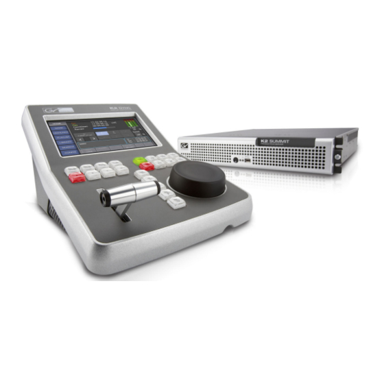
Replay controller
Hide thumbs
Also See for K2 Dyno:
- Datasheet (8 pages) ,
- Quick start manual (36 pages) ,
- Quick start manual (34 pages)
Table of Contents
Advertisement
Quick Links
Advertisement
Table of Contents

Related Manuals for GRASS VALLEY K2 Dyno


Summary of Contents for GRASS VALLEY K2 Dyno
- Page 1 K2 Dyno Replay Controller Service Manual 071-8702-02 February 2012...
- Page 2 Affiliate with the N.V. KEMA in The Netherlands CERTIFICATE CERTIFICATE Certificate Number: 510040.001 The Quality System of: Certificate Number: 510040.001 Thomson Inc, and its wor dwide Grass Valley division affiliates DBA GRASS VALLEY The Quality System of: Headquarters 15655 SW Greystone Ct. 10 Presidential Way...
- Page 3 K2 Dyno Replay Controller Service Manual 071-8702-02 February 2012...
- Page 4 Benelux/Belgium: +32 (0) 2 334 90 30 Benelux/Netherlands: +31 (0) 35 62 38 42 1 N. Europe: +45 45 96 88 70 Germany, Austria, Eastern Europe: +49 6150 104 444 UK, Ireland, Israel: +44 118 923 0499 Copyright © Grass Valley USA, LLC. All rights reserved. This product may be covered by one or more U.S. and foreign patents.
-
Page 5: Table Of Contents
BIOS startup information ..................51 Shutdown/restart problems ..................51 Checking external equipment .................. 52 VGA display problems ..................52 Keyboard and mouse problems................52 BIOS startup......................52 BIOS POST error messages ................... 52 02 February 2012 K2 Dyno Replay Controller Service Manual... - Page 6 Cabling diagram with Type II control panel UI board ..........82 USB board removal....................83 Power supply removal ..................... 84 Appendix A Trademarks and Agreements Trademarks ......................86 Index ........................87 K2 Dyno Replay Controller Service Manual 02 February 2012...
-
Page 7: Safety Summaries
Safety Summaries Read the following sections for important safety information. • Safety Summary • Sicherheit – Überblick • Consignes desécurité • Certifications and compliances • ESD Protection 02 February 2012 K2 Dyno Replay Controller Service Manual... - Page 8 This is a prompt to note fuse rating when replacing fuse(s). The fuse referenced in the text must be replaced with one having the ratings indicated. K2 Dyno Replay Controller Service Manual 02 February 2012...
- Page 9 Double pole neutral fusing — Do not use door latches to lift or move equipment. Use proper lift points — Allow all rotating devices to come to a stop before Avoid mechanical hazards servicing. 02 February 2012 K2 Dyno Replay Controller Service Manual...
- Page 10 (ASICS). As a result, circuit board repair at the component level is very difficult in the field, if not impossible. For warranty compliance, do not troubleshoot systems beyond the board level. K2 Dyno Replay Controller Service Manual 02 February 2012...
- Page 11 Ausrüstungskomponenten. Symbole am Produkt Die folgenden Symbole können sich am Produkt befinden: Weist auf eine gefährliche Hochspannung im Gerätegehäuse hin, die stark genug sein kann, um eine Stromschlaggefahr darzustellen. 02 February 2012 K2 Dyno Replay Controller Service Manual...
- Page 12 – Betreiben Sie das Gerät nicht in nassen Gerät nur in trockener Umgebung verwenden oder feuchten Umgebungen. – Verwenden Sie dieses Gerät nur verwenden, wenn keine Explosionsgefahr besteht Produkt nur in Umgebungen, in denen keinerlei Explosionsgefahr besteht. K2 Dyno Replay Controller Service Manual 02 February 2012...
- Page 13 Explosionsgefahr zu verringern, prüfen Sie die Polarität und tauschen die Batterie nur gegen eine Batterie desselben Typs oder eines gleichwertigen, vom Hersteller empfohlenen Typs aus. Entsorgen Sie gebrauchte Batterien entsprechend den Anweisungen des Batterieherstellers. 02 February 2012 K2 Dyno Replay Controller Service Manual...
- Page 14 Safety Summaries Das Gerät enthält keine Teile, die vom Benutzer gewartet werden können. Wenden Sie sich bei Problemen bitte an den nächsten Händler. K2 Dyno Replay Controller Service Manual 02 February 2012...
- Page 15 Les symboles suivants peut être apposés sur le produit : Signale la présence d’une tension élevée et dangereuse dans le boîtier de l’équipement ; cette tension peut être suffisante pour constituer un risque de décharge électrique. 02 February 2012 K2 Dyno Replay Controller Service Manual...
- Page 16 Utilisez ce produit exclusivement dans un environnement sec produit dans un environnement humide. — N’utilisez Utilisez ce produit exclusivement dans un environnement non explosible pas ce produit dans un environnement dont l’atmosphère est explosible. K2 Dyno Replay Controller Service Manual 02 February 2012...
- Page 17 L’utilisation de cet équipement à des tensions dépassant les 130 V en c.a. requiert des cordons d’alimentation qui satisfont aux exigences des configurations NEMA. Les cordons internationaux, s’ils sont fournis, ont reçu l’approbation du pays dans lequel l’équipement est utilisé. 02 February 2012 K2 Dyno Replay Controller Service Manual...
- Page 18 Mettez les piles usagées au rebut conformément aux instructions du fabricant des piles. Cette unité ne contient aucune partie qui peut faire l’objet d’un entretien par l’utilisateur. Si un problème survient, veuillez contacter votre distributeur local. K2 Dyno Replay Controller Service Manual 02 February 2012...
- Page 19 Operation of this equipment in a residential area is likely to cause harmful interference in which case the user will be required to correct the interference at his own expense. Changes or modifications not expressly approved by Grass Valley can affect emission compliance and could void the user’s authority to operate this equipment.
- Page 20 (Second edition, 2005). CAN/CSA C22.2 No. Safety of Information Technology Equipment, 60950-1 including Electrical Business Equipment (Second edition 2007). BS EN 60950-1 Safety of Information Technology Equipment, including Electrical Business Equipment 2006. K2 Dyno Replay Controller Service Manual 02 February 2012...
- Page 21 Damage to equipment can occur by ESD fields that are smaller than you can feel. Implementing the information in this section will help you protect the investment that you have made in purchasing Grass Valley equipment. This section contains Grass Valley’s recommended ESD guidelines that should be followed when handling electrostatic discharge sensitive (ESDS) items.
- Page 22 Wrist Strap System* ESD TR53 Wrist Strap Section < 3.5 x 10 Flooring / Footwear System – ESD TR53 Flooring Section and < 3.5 x 10 Method 1 ESD TR53 Footwear Section K2 Dyno Replay Controller Service Manual 02 February 2012...
- Page 23 * For situations where an ESD garment is used as part of the wrist strap grounding path, the total system resistance, including the person, garment, and grounding cord, must be less than 3.5 x 10 ohm. 02 February 2012 K2 Dyno Replay Controller Service Manual...
- Page 24 Safety Summaries K2 Dyno Replay Controller Service Manual 02 February 2012...
-
Page 25: Finding Information
— The release notes contain the latest information about the software Release Notes shipped on your system. There are K2 Release Notes and K2 Dyno Replay Controller Release Notes. The information in release notes includes software upgrade instructions, software specifications and requirements, feature changes from the previous releases, and any known problems. - Page 26 Finding Information • — Contains information on servicing and K2 Dyno Replay Controller Service Manual maintenance. • — The Quick Start Guide provides K2 Summit Production Client Quick Start Guide step-by-step installation instructions for basic installation and operation of K2 systems, including recording and playing clips.
-
Page 27: Product Description
•“Overview description” on page 28 •“Dyno controller orientation” on page 29 •“FRU functional descriptions” on page 30 •“Status indicators” on page 34 •“General specifications” on page 35 •“Counter top installation” on page 36 02 February 2012 K2 Dyno Replay Controller Service Manual... -
Page 28: Overview Description
Interface tools include thumbnail icons, status indicators, specialized windows, and drag-and-drop operations for speedy and easy use. Refer to the K2 Dyno Replay Controller User Manual for descriptions of features, controls, applications, and subsystems. K2 Dyno Replay Controller Service Manual... -
Page 29: Dyno Controller Orientation
UI board is in a similar position. With the Type II control panel UI board there is a also a Type II encoder (not shown) that is a separate unit, rather than being integrated into the board. 02 February 2012 K2 Dyno Replay Controller Service Manual... -
Page 30: Fru Functional Descriptions
“Job knob removal” on page 60 for procedures. Plastic cover The plastic top cover provides the finished work surface with access holes for controls. Refer to “Plastic cover removal” on page 70 for procedures. K2 Dyno Replay Controller Service Manual 02 February 2012... -
Page 31: T-Bar Lever Assembly
• T-bar lever A/D interface • SPI Port to LCD screen Controller • LED driver interface • Button LED Dimming • Embedded Program Flash and SRAM memory • Display Interface • LCD screen controller 02 February 2012 K2 Dyno Replay Controller Service Manual... -
Page 32: Type Ii Encoder
Compact Flash slot, and rear panel connectors as follows: • 2 Giga-bit Ethernet • 15 pin (D-conn) VGA • DB-9 serial port. Refer to “Motherboard removal” on page 80 for procedures. K2 Dyno Replay Controller Service Manual 02 February 2012... -
Page 33: Power Supply
It is an ATX Power supply of 180 Watts. Refer to “Power supply removal” on page 84 for procedures. 02 February 2012 K2 Dyno Replay Controller Service Manual... -
Page 34: Status Indicators
Off: No drive access is occurring. LAN connector indicator codes The motherboard has two RJ-45 LAN connectors that include integrated status LEDs. The LEDs are oriented as follows: Green Green/Yellow/Orange K2 Dyno Replay Controller Service Manual 02 February 2012... -
Page 35: System Beep Codes
= 8.25 in. (210 mm); height = 7.4 in.(187 mm) (All approx.) Weight 5 kg (11 lbs.) Temperature range Operating: 0°C to 40°C (32°F to 104°F); Storage: -20°C to 60°C (-4°F to 140°F) Humidity range 10% to 90% (relative humidity) 02 February 2012 K2 Dyno Replay Controller Service Manual... -
Page 36: Counter Top Installation
Chapter 1 Product Description Counter top installation Use the following specifications for a custom installation in a counter top. K2 Dyno Replay Controller Service Manual 02 February 2012... -
Page 37: Service Procedures
In version 2.x, the K2 Dyno Replay application no longer exports logs. Logs are stored on the K2 Summit Production Client or Solo. Exporting log files (software version 1.x) 1. In the K2 Dyno Replay application on the K2 Dyno Replay Controller LCD screen, select the tab. -
Page 38: Upgrading Software
For procedures to upgrade software on the Dyno controller, refer to the K2 Dyno Replay Controller Release Notes for the version to which you are upgrading. Also refer to K2 Release Notes to upgrade related software on the K2 Summit Production Client. -
Page 39: Using Recovery Disk Images
These “first birthday” images are the baseline recovery image for the Dyno controller in its life in your facility. There is enough disk space on the Recovery Flash Drive to store the first birthday image along with the factory image. 02 February 2012 K2 Dyno Replay Controller Service Manual... -
Page 40: Creating A Recovery Disk Image
If a “…choose full backup mode…” message appears, click The Backup Archive Location page opens. 7. In the tree view select as the location to which you are writing Removable Drive (A:) the disk image. K2 Dyno Replay Controller Service Manual 02 February 2012... -
Page 41: Restoring From A System-Specific Recovery Disk Image
Then press the standby button again to startup. The machine boots from the Flash drive. The Acronis True Image program loads. 4. In the Acronis True Image main window, click Recovery The Restore Data Wizard opens. 02 February 2012 K2 Dyno Replay Controller Service Manual... - Page 42 . This is the Recovery Flash Drive. Removable Drive (A:) Select the image file. The file for the image supplied by the Grass Valley factory is named with the serial number of the Dyno controller. • Navigate to the location of the image file from which you are restoring.
-
Page 43: Restoring From A Generic Recovery Disk Image
C: partition. This should be the same as that reported in the Partition size field in the middle of the page. Free space before and Free space after should both be reported at 0 bytes. Click Next The Next Selection page opens. 02 February 2012 K2 Dyno Replay Controller Service Manual... -
Page 44: Replacing A Dyno Controller
Do not enter the serial number. Replacing a Dyno controller To correct some system faults Grass Valley Support sends you a replacement Dyno controller. Contact Grass Valley Support if you think you need a replacement Dyno controller. - Page 45 Replacing a Dyno controller 02 February 2012 K2 Dyno Replay Controller Service Manual...
- Page 46 Chapter 2 Service Procedures K2 Dyno Replay Controller Service Manual 02 February 2012...
-
Page 47: Troubleshooting Problems
Chapter Troubleshooting problems If you think there is something wrong (broken) with your K2 Dyno Replay Controller, go through the following preliminary steps: • “Step 1: Check configurations” on page 48 • “Step 2: Check connections and external equipment” on page 48 •... -
Page 48: Step 1: Check Configurations
“Run hardware diagnostics (software version 1.x)” on page 50 Run hardware diagnostics (software version 2.x) To run the hardware diagnostics, you need to start up the K2 Dyno Replay Controller in Maintenance mode. With the Dyno controller diagnostics, you can check if the hardware is operating normally as to whether: •... - Page 49 Exit 5. When you exit the diagnostics, you are returned to the Windows desktop. To re-start the Dyno software, click on the Dyno icon on the desktop. 02 February 2012 K2 Dyno Replay Controller Service Manual...
-
Page 50: Run Hardware Diagnostics (Software Version 1.X)
• the hardware responds to the JOG operations properly • the touch panel detects correct positions • the touch panel brightness can be changed 1. Start up the K2 Dyno Replay Controller. 2. When the Select Session Mode screen appears, press the , and... -
Page 51: Bios Startup Information
BIOS startup information When you exit the diagnostics, both the software and hardware is shut down, and the K2 Dyno Replay Controller is turned off. BIOS startup information The following information appears during a normal startup of the Dyno controller. -
Page 52: Checking External Equipment
If a message is displayed, it will be accompanied by the following: PRESS F1 TO CONTINUE, CTRL-ALT-ESC OR DEL TO ENTER SETUP To correct problems of this nature, contact Grass Valley Support. The following is a list of BIOS POST error messages. BIOS Message... - Page 53 CNTRLR PRESENT controller. Make sure the controller is installed correctly and firmly. If there are no floppy drives installed, be sure the Diskette Drive selection in Setup is set to NONE. 02 February 2012 K2 Dyno Replay Controller Service Manual...
- Page 54 NMI and continue to boot, or you can reboot the system with the NMI enabled. RAM PARITY ERROR - CHECKING FOR Indicates a parity error in Random Access SEGMENT ... Memory. K2 Dyno Replay Controller Service Manual 02 February 2012...
- Page 55 BIOS ROM checksum error - System halted. The checksum of ROM address F0000H-FFFFFH is bad. Memory test fail. BIOS reports the memory test fail if the onboard memory is tested error. 02 February 2012 K2 Dyno Replay Controller Service Manual...
-
Page 56: Windows Startup
(such as networking), the Windows operating system is not operating as it should. To correct problems of this nature, restore the system drive image. Refer to “Using recovery disk images” on page K2 Dyno Replay Controller Service Manual 02 February 2012... -
Page 57: Lcd Screen Problems
The power supply is faulty. This Replace the power supply is indicated if the front panel power indicator does not come If the power source and the power cord are OK, replace the power supply. 02 February 2012 K2 Dyno Replay Controller Service Manual... -
Page 58: Isolating Functional Problems
Faulty software or LCD screen. Reimage Dyno. If problem remains, replace LCD screen Faulty software. Reimage Dyno. Faulty video/audio feed. Check video/audio source. Faulty VGA connection or monitor. Check connections and monitor. Summit problem. Check connections. Reimage Summit. K2 Dyno Replay Controller Service Manual 02 February 2012... -
Page 59: Chapter 4 Removing And Replacing Frus
You can also replace the entire Dyno controller as a FRU, as explained in “Replacing a Dyno controller” on page NOTE: Only Grass Valley components are supported. Do not attempt to use components procured from a different source. NOTE: Do not discard any hardware unless specifically instructed to do so. -
Page 60: Job Knob Removal
Chapter 4 Removing and replacing FRUs Job knob removal Remove the job knob as illustrated. Loosen set screw. Use 2 mm allen wrench. K2 Dyno Replay Controller Service Manual 02 February 2012... -
Page 61: Control Panel Ui Board Identification
If your Dyno Controller has a Type II control panel UI board, it also has a Type II encoder. Continue with the procedures as appropriate for the Type I or Type II components. 02 February 2012 K2 Dyno Replay Controller Service Manual... -
Page 62: Job Knob Bearing Assembly Removal
Chapter 4 Removing and replacing FRUs Job knob bearing assembly removal If your K2 Dyno Controller has a Type I control panel UI board without the bearing kit installed, remove the bearing assembly under the jog knob as illustrated. Remove washers and bearing Remove nut and toothed washer. - Page 63 Job knob bearing assembly removal If your K2 Dyno Controller has a Type I control panel UI board with the bearing kit installed, remove the bearing assembly under the jog knob as illustrated. Knob Large washer Toothed washer Bearing Small...
-
Page 64: Job Knob Replacement
When replacing the job knob, replace washers and bearings, then align the knob as illustrated. Align set screw with flat on shaft. T-bar lever handle removal Remove the T-bar lever handle as illustrated. Disassemble using 1/8” allen wrench K2 Dyno Replay Controller Service Manual 02 February 2012... -
Page 65: Compact Flash Boot Media Removal
Compact Flash boot media removal Compact Flash boot media removal Remove the Compact Flash boot media from the rear panel, as illustrated. Disengage using a flat screwdriver Slide out 02 February 2012 K2 Dyno Replay Controller Service Manual... -
Page 66: Top Removal
To access the internal hardware, or if you are replacing the top unit as a pre-assembled FRU, remove the top as shown: Remove 3 rear screws Remove 3 front screws Flip top off Provide padding/shims to protect paint and stabilize position of top unit K2 Dyno Replay Controller Service Manual 02 February 2012... -
Page 67: Top Unit Cable Removal Type I Control Panel Ui Board
Use small flat screwdriver to disconnect and re-connect. To disconnect, pry up gently at corners. To re-connect, seat firmly in center and in corners. Make sure the connector is not bowed up in the middle. 02 February 2012 K2 Dyno Replay Controller Service Manual... -
Page 68: Top Unit Cable Removal Type Ii Control Panel Ui Board
Use small flat screwdriver to disconnect and re-connect. To disconnect, pry up gently at corners. To re-connect, seat firmly in center and in corners. Make sure the connector is not bowed up in the middle. K2 Dyno Replay Controller Service Manual 02 February 2012... -
Page 69: Top Replacement
To remove the T-bar lever assembly, first remove the T-bar lever handle and the top, then work on the top unit separately, as illustrated. Remove 4 screws. Use Torx T-10. Disconnect cable 02 February 2012 K2 Dyno Replay Controller Service Manual... -
Page 70: Plastic Cover Removal
To remove the plastic cover, first remove the jog knob, T-bar lever handle, and top, then work on the top unit separately, as illustrated. Remove 7 screws Remove plastic cover from top K2 Dyno Replay Controller Service Manual 02 February 2012... -
Page 71: Lcd Screen Inverter Board Removal
LCD screen inverter board removal To remove the LCD screen inverter board, first remove the top, then work on the top unit separately, as illustrated. Remove two screws. Use P1 Phillips. Remove two cables 02 February 2012 K2 Dyno Replay Controller Service Manual... -
Page 72: Type I Control Panel Ui Board Removal
Make sure the connector is not bowed up in the middle. Slide flange out to release cable. Gently pry up black lever with two fingernails to release cable. Continue with next illustration. K2 Dyno Replay Controller Service Manual 02 February 2012... - Page 73 Type I control panel UI board removal Remove 13 screws 02 February 2012 K2 Dyno Replay Controller Service Manual...
-
Page 74: Type Ii Control Panel Ui Board Removal
Make sure the connector isnot bowed up in the middle. Slide flange out to release cable. Gently pry up black lever with two fingernails to release cable. Continue with next illustration. K2 Dyno Replay Controller Service Manual 02 February 2012... - Page 75 Type II control panel UI board removal Remove 13 screws 02 February 2012 K2 Dyno Replay Controller Service Manual...
-
Page 76: Type Ii Encoder Removal
Remove 4 nuts encoder wire Identify red ecoder wire orientation, then disconnect K2 Dyno Replay Controller Service Manual 02 February 2012... -
Page 77: Lcd Screen Removal
Disconnect LCD screen Slide flange out inverter board cable to release cable. Gently pry up white lever with thumbnail to release cable. Continue with the next illustration. 02 February 2012 K2 Dyno Replay Controller Service Manual... -
Page 78: Front I/O Board Removal
Front I/O board removal To remove the front I/O board, first remove the top, then proceed as illustrated. Disconnect 4 cables Remove 2 screws Remove nut and washer from audio connector K2 Dyno Replay Controller Service Manual 02 February 2012... -
Page 79: Fan Removal
Fan removal Fan removal To remove the fan, first remove the top, then proceed as illustrated. Disconnect cable. Cut cable ties as necessary Remove 4 screws. Use Phillps P1. Remove fan screen 02 February 2012 K2 Dyno Replay Controller Service Manual... -
Page 80: Motherboard Removal
Cut zip tie and release battery. When installing the replacement motherboard, use the battery that comes with the replacement motherboard. Do not use the battery that was connected to the faulty motherboard. K2 Dyno Replay Controller Service Manual 02 February 2012... -
Page 81: Cabling Diagram With Type I Control Panel Ui Board
Cabling diagram with Type I control panel UI board LCD screen Power Supply LCD screen inverter board Front I/O board Control panel UI board Motherboard P1 P1 USB board P2 P2 P3 P3 02 February 2012 K2 Dyno Replay Controller Service Manual... -
Page 82: Cabling Diagram With Type Ii Control Panel Ui Board
Front I/O board Control panel UI board Red encoder Red encoder wire wire Red encoder Red encoder wire wire Encoder Motherboard P1 P1 USB board P2 P2 P3 P3 K2 Dyno Replay Controller Service Manual 02 February 2012... -
Page 83: Usb Board Removal
USB board removal USB board removal To remove the USB board, first remove the top, fan, and motherboard, then proceed as illustrated. Disconnect 4 cables Remove 3 screws 02 February 2012 K2 Dyno Replay Controller Service Manual... -
Page 84: Power Supply Removal
Chapter 4 Removing and replacing FRUs Power supply removal To remove the power supply, first remove the top, front I/O board, fan, motherboard, and USB board, then proceed as illustrated. Remove 3 screws. Remove 2 screws K2 Dyno Replay Controller Service Manual 02 February 2012... -
Page 85: Appendix A Trademarks And Agreements
Appendix Trademarks and Agreements 02 February 2012 K2 Dyno Replay Controller Service Manual... -
Page 86: Trademarks
NewsShare, NewsQ Pro, and Media Manager are either registered trademarks or trademarks of Grass Valley USA, LLC. in the United States and/or other countries. Grass Valley USA, LLC. products are covered by U.S. and foreign patents, issued and pending. Additional information regarding Grass Valley USA, LLC. trademarks and other proprietary rights may be found at www.grassvalley.com. -
Page 87: Index
32 shutdown problems 51 software download from web 4 specification Grass Valley web site 4 general 35 standby switch 34 startup sequence indicators troubleshooting 48 descriptions 34 system drive description 30 02 February 2012 K2 Dyno Replay Controller Service Manual... - Page 88 4 web site FAQ database 4 web site Grass Valley 4 web site software download 4 web site, for Grass Valley 26 Windows startup 56 startup troubleshooting 56 K2 Dyno Replay Controller Service Manual 02 February 2012...
Need help?
Do you have a question about the K2 Dyno and is the answer not in the manual?
Questions and answers