Table of Contents
Advertisement
Available languages
Available languages
Quick Links
Betriebsanleitung
Operating instructions
Notice technique
Instrukcja eksploatacji
ÖWWG 3
ÖWWG 3 (230 V)
ÖWWG 3 (24 V)
Vor Gebrauch lesen!
Alle Sicherheitshinweise beachten!
Für künftige Verwendung aufbewahren!
06.2022.0
854.099.0122
Mess-, Regel- und
Überwachungsgeräte
für Haustechnik,
Industrie und Umweltschutz
Lindenstraße 20
74363 Güglingen
Telefon +49 7135 102-0
Service +49 7135 102-211
Telefax +49 7135 102-147
info@afriso.de
www.afriso.de
Leckanzeiger
Z-65.40-339
Advertisement
Chapters
Table of Contents

Subscribe to Our Youtube Channel
Related Manuals for Afriso EURO-INDEX OWWG 3


Summary of Contents for Afriso EURO-INDEX OWWG 3
- Page 1 Mess-, Regel- und Überwachungsgeräte für Haustechnik, Industrie und Umweltschutz Lindenstraße 20 74363 Güglingen Telefon +49 7135 102-0 Service +49 7135 102-211 Telefax +49 7135 102-147 info@afriso.de www.afriso.de Betriebsanleitung Operating instructions Leckanzeiger Z-65.40-339 Notice technique Instrukcja eksploatacji ÖWWG 3 ÖWWG 3 (230 V) ÖWWG 3 (24 V) ...
- Page 2 Mess-, Regel- und Überwachungsgeräte für Haustechnik, Industrie und Umweltschutz Lindenstraße 20 74363 Güglingen Telefon +49 7135 102-0 Service +49 7135 102-211 Telefax +49 7135 102-147 info@afriso.de www.afriso.com Betriebsanleitung Öl-Wasser-Warngerät Leckage- ÖWWG 3 erkennungs- system Z-65.40-339 ÖWWG 3 (230 V) ÖWWG 3 (24 V) ...
-
Page 3: Table Of Contents
Inhaltsverzeichnis Zu dieser Betriebsanleitung ..................4 Aufbau der Warnhinweise ................4 Sicherheit ......................... 5 Bestimmungsgemäße Verwendung ............. 5 Vorhersehbare Fehlanwendung ..............6 Sichere Handhabung ................... 6 Qualifikation des Personals ................7 Persönliche Schutzausrüstung..............7 Veränderungen am Produkt ................. 8 Verwendung von Ersatzteilen und Zubehör ..........8 Produktbeschreibung.................... - Page 4 13 Gewährleistung ...................... 29 14 Ersatzteile und Zubehör ..................29 15 Informationenzu EnOcean ® -Funk ................30 15.1 Reichweiten des EnOcean®-Funks ............30 15.2 Weiterführende Informationen zu EnOcean -Funksystemen ....30 ® 15.3 Möglichkeiten der EnOcean ® -Technologie ..........30 16 Anhang ........................
-
Page 5: Zu Dieser Betriebsanleitung
Zu dieser Betriebsanleitung – Deutsch – Zu dieser Betriebsanleitung Diese Betriebsanleitung ist Teil des Produkts. Betriebsanleitung vor dem Gebrauch des Produkts lesen. Betriebsanleitung während der gesamten Lebensdauer des Pro- dukts aufbewahren und zum Nachschlagen bereithalten. Betriebsanleitung an jeden nachfolgenden Besitzer oder Benut- ... -
Page 6: Sicherheit
– Deutsch – Sicherheit Sicherheit Bestimmungsgemäße Verwendung Das Öl-Wasser-Warngerät ÖWWG 3 eignet sich ausschließlich zur Meldung von Flüssigkeitsansammlungen und zur Überwachung von: Rückhalteeinrichtungen unter Lagerbehältern, Brennern, Moto- • ren oder Geräten Behältern (Tanks) mit nicht einsehbaren Rückhalteeinrichtungen • Räumen zur frühzeitigen Meldung von Flüssigkeitsansammlun- •... -
Page 7: Vorhersehbare Fehlanwendung
Sicherheit – Deutsch – DWA-A 791 bzw. Leckageerkennungssystem nach Arbeitsblatt DWA-A 779. Eine andere Verwendung ist nicht bestimmungsgemäß und ver- usacht Gefahren. Vorhersehbare Fehlanwendung Das Öl-Wasser-Warngerät ÖWWG 3 darf insbesondere in folgenden Fällen und für folgende Zwecke nicht angewendet werden: Flüssigkeiten, die zur Dickflüssigkeit neigen oder die zu Verkle- •... -
Page 8: Qualifikation Des Personals
– Deutsch – Sicherheit WARNUNG Schwere Brandverletzungen, Explosionen, Verpuffungen oder Brand durch Temperaturen bis 100 °C an Sondenspitze. Sondenspitze nicht berühren. HINWEIS Beeinträchtigung der Gerätefunktionen durch extreme Umge- bungsbedingungen. Produkt vor Feuchtigkeit schützen. Produkt vor Witterung und direkter Sonneneinstrahlung schüt- ... -
Page 9: Veränderungen Am Produkt
Sicherheit – Deutsch – Veränderungen am Produkt Führen Sie ausschließlich solcher Arbeiten an und mit dem Produkt durch, die in dieser Betriebsanleitung beschrieben sind. Nehmen Sie keine Veränderungen vor, die in dieser Betriebsanleitung nicht be- schrieben sind. Verwendung von Ersatzteilen und Zubehör Durch Verwendung nicht geeigneter Ersatz- und Zubehörteile kann das Produkt beschädigt werden. -
Page 10: Produktbeschreibung
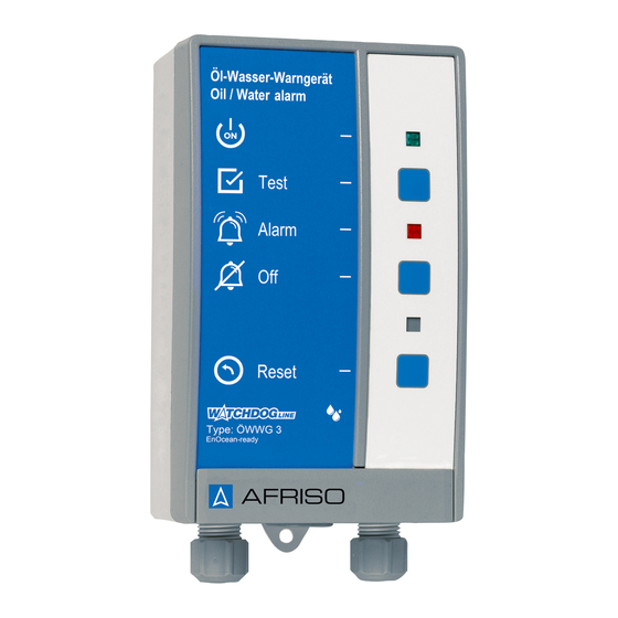
– Deutsch – Produktbeschreibung Produktbeschreibung Lieferumfang Signalteil mit integrierten LEDs und abschaltbarem Summer • Kaltleitersonde • Eigenschaften Das Öl-Wasser-Warngerät ÖWWG 3 besteht aus einem fehlersiche- ren selbstüberwachenden Signalteil mit periodischem Selbsttest und einer Sonde. Signalteil und Sonde werden durch eine zweiadrige Signalleitung miteinander verbunden. - Page 11 Produktbeschreibung – Deutsch – Signalteil Das Signalteil enthält in einem schlagfesten Kunststoffgehäuse die Anzeige- und Bedienelemente sowie sämtliche elektronische Kom- ponenten zur Auswertung des Sondensignals. Das Signalteil verfügt über einen potentialfreien Wechselkontakt zur Weitermeldung des Alarmfalls an zusätzliche Geräte. Grüne LED Prüftaste Rote LED Quittiertaste...
-
Page 12: Funktion
– Deutsch – Produktbeschreibung Funktion ÖWWG 3 kann das Auftreten von Flüssigkeitsansammlungen erken- nen. Nach dem Einschalten der Netzspannung leuchtet die grüne LED und der Aufheizvorgang des Kaltleiters beginnt. Bis zum Errei- chen der Betriebstemperatur ertönt der akustische Alarm und die rote LED leuchtet. -
Page 13: Anwendungsbeispiele
Produktbeschreibung – Deutsch – Anwendungsbeispiele Netzspannung Signalteil Steuerleitung Abwasserpumpe Kaltleitersonde Maximaler Stand Minimaler Stand Restwasser Bild 3: Abwasser-Pumpensteuerung mit automatischer Öl-Sicher- heitsschaltung Bei automatischen Entwässerungspumpen in Rückhalteeinrichtun- gen von Öltanks besteht die Gefahr, dass bei einer Undichtheit auch Öl in den Abwasserkanal abgepumpt wird. Die Kombination ÖWWG 3 und ELT 8 mit entsprechend hierfür ausgewählten Sonden verhindert einen Ölschaden. - Page 14 – Deutsch – Produktbeschreibung Bild 4: Anwendungsbeispiele 1 Signalteil Wasserleitungen 13 Transformatoren 2 Kaltleitersonde im Schutzrohr Batterietank 14 Ölbefeuerte Kessel- anlage 3 Lagertank oberirdisch Auffangwanne 4 Wasseraufbereitung, Heiz- 10 Kaltleitersonde 15 Ölleitung räume 11 Domschacht unter- 16 Doppelmantel irdischer Tank Schutzrohr 5 Waschräume, Küchen, Keller 12 Lagertank unterir-...
-
Page 15: Technische Daten
Technische Daten – Deutsch – Technische Daten Tabelle 1: Technische Daten Signalteil Parameter Wert Allgemeine Daten Maße Gehäuse (B x H x T) 100 x 188 x 65 mm Gewicht 0,6 kg Werkstoff Gehäuse Kunststoff ABS Ansprechverzögerung Keine Umgebungsbedingungen Umgebungstemperatur -5 °C …... - Page 16 – Deutsch – Technische Daten Parameter Wert Störaussendung EN 61000-6-3 Störfestigkeit EN 61000-6-2 Bemessungsstoßspannung 2500 V Verschmutzungsgrad EnOcean -Funk ® Frequenz 868,3 MHZ Sendeleistung Max. 10 mW Reichweite Siehe Kapitel 15, Seite 30 EnOcean Equipment Profile A5-30-04 (EEP) Tabelle 2: Technische Daten Sonde Parameter Wert Allgemeine Daten...
-
Page 17: Zulassungsdokumente, Bescheinigungen, Erklärungen
Transport und Lagerung – Deutsch – Zulassungsdokumente, Bescheinigungen, Erklärungen Das Produkt ist TÜV-geprüft und entspricht: EMV-Richtlinie (2014/30/EU) • • Niederspannungsrichtlinie (2014/35/EU) RoHS-Richtlinie (2011/65/EU) • Das Produkt mit EnOcean®-Funk entspricht zusätzlich: Radio Equipment Directive, RED (2014/53/EU) • Zulassungen: Allgemeine bauaufsichtliche Zulassung Z-65.40-339 Transport und Lagerung HINWEIS Beschädigung des Produkts durch unsachgemäßen Transport. -
Page 18: Montage Und Inbetriebnahme
– Deutsch – Montage und Inbetriebnahme Montage und Inbetriebnahme Die zulässigen Umgebungbedingungen einhalten. Sicherstellen, dass das akustische Warnsignal des Signalteils auch bei Umgebungsgeräuschen jederzeit wahrgenommen wer- den kann. Wenn die Hörbarkeit nicht sichergestellt werden kann, muss ein Zu- satzalarmgerät an geeigneter Stelle angebracht werden (beispiels- weise das Zusatzalarmgerät ZAG 01, die Hupe KH 1 oder die Warn- lichthupe von AFRISO). - Page 19 Montage und Inbetriebnahme – Deutsch – Signalteil öffnen. Signalteil an der Wand befestigen (A oder B). A 1 Schraube an der Wand befestigen. B Befestigungslöcher im Unterteil mit Bohrer Ø 5 mm durchbohren. 2 Signalteil einhängen. Unterteil mit beiligenden Schrau- 3 Signalteil mit Schraube durch untere La- ben an der Wand befestigen.
-
Page 20: Elektrischer Anschluss
– Deutsch – Montage und Inbetriebnahme Signalteil schließen. Elektrischer Anschluss Wenn ÖWWG 3 als Sicherheitseinrichtung eingesetzt ist, muss das Produkt mit einer fest verlegten Leitung angeschlossen sein. Netzspannung ist unterbrochen und gegen Wiedereinschalten gesichert. Sondensicherung F2 Sondenanschluss Externe Entriegelung Relais für zusätzliche Geräte Spannungsversorgung 230 V Bild 5: Elektrischer Anschluss 230 V ÖWWG 3... - Page 21 Montage und Inbetriebnahme – Deutsch – Spannungsversorgung Signalteil Netzanschluss ist mit einer fest verlegten, geeigneten Leitung (beispielsweise NYM-J 3x1,5 mm²). Die Zuleitung zum Signalteil ist separat abgesichert (maxi- mal 16 A). Das Netzkabel durch die linke Verschraubung in das Signalteil ...
- Page 22 – Deutsch – Montage und Inbetriebnahme Nachrüstung eines EnOcean -Funkmoduls (optional) ® Netzspannung ist unterbrochen und gegen Wiedereinschalten gesichert. Den Deckel des Signalteils öffnen. HINWEIS Schäden an elektronischen Bauteilen durch elektrostatische Entladung. Erden Sie sich grundsätzlich, bevor Sie die elektronischen Bau- ...
- Page 23 Montage und Inbetriebnahme – Deutsch – Das EnOcean ® -Funkmodul in den Steckplatz einsetzen. Beim Einsetzen folgendes sicherstellen: Die Antenne muss auf der rechten Seite entlang der Gehäuse- wand in die Aussparung (3) geklemmt sein. Alle Pins müssen in die Buchsenleiste gesteckt sein. ...
-
Page 24: Öwwg 3 Mit Afrisohome Gateway Verbinden (Optional)
– Deutsch – Montage und Inbetriebnahme ÖWWG 3 mit AFRISOhome Gateway verbinden (optional) Der Einlernvorgang ist in der Betriebsanleitung des AFRISOhome Gateways oder der App beschrieben. ÖWWG 3 ist ordnungsgemäß montiert und elektrisch ange- schlossen. ÖWWG 3 befindet sich in der Nähe des AFRISOhome Gate- ways. -
Page 25: Produkt In Betrieb Nehmen
Montage und Inbetriebnahme – Deutsch – Produkt in Betrieb nehmen In Verbindung mit der neuen, ummantelten Kaltleitersonde kann es vorkommen, dass die rote LED nicht erlischt oder der akustische Alarm nicht verstummt. Drücken Sie in diesem Fall die "Reset-Taste", um den Alarmzustand zu quittieren. -
Page 26: Betrieb
– Deutsch – Betrieb 7 Betrieb Die Bedienung des ÖWWG 3 beschränkt sich auf dessen regelmä- ßige Überwachung: Die grüne LED leuchtet. • Die rote LED leuchtet nicht. • • Der akustische Alarm ertönt nicht. Alarm Wenn der Kaltleiter Flüssigkeit detektiert, verändert sich der Wider- stand des Kaltleiters und das Signalteil gibt Alarm. -
Page 27: Wartung
Wartung – Deutsch – Wartung Die Art der Prüfung und die Zeitabstände im genannten Zeitrahmen liegen in der Betreiberverantwortung. Wartungsintervalle Wann Tätigkeit Monatlich Sichtprüfung auf Beschädigungen, Korro- sion und Verschmutzungen durchführen. Zweimal jährlich Funktionsprüfung durchführen, siehe Ka- pitel 6.8, Seite 24. Jährlich und bei Funktionsprüfung durchführen, siehe Ka- ... -
Page 28: Wartungstätigkeiten
– Deutsch – Wartung Wartungstätigkeiten Netzsicherung F1 tauschen Netzspannung ist unterbrochen und gegen Wiedereinschalten gesichert. Signalteil öffnen, siehe Kapitel 6.2, Seite 17. Transparente Abdeckhaube von der Netzsicherung F1 abneh- men. Netzsicherung F1 ersetzen, siehe Tabelle 1, Seite 14. Transparente Abdeckhaube auf die Netzsicherung F1 auf- schnappen. -
Page 29: Störungen
Störungen – Deutsch – Störungen Das Produkt ist eine Sicherheitseinrichtung. Störungen, die nicht durch die im Kapitel beschriebenen Maßnah- men beseitigt werden können, dürfen nur durch den Hersteller beho- ben werden. Problem Mögliche Ursache Fehlerbehebung Grüne LED leuch- Netzspannung unter- Netzspannung wie- ... -
Page 30: Außerbetriebnahme Und Entsorgung
– Deutsch – Außerbetriebnahme und Entsorgung 11 Außerbetriebnahme und Entsorgung Entsorgen Sie das Produkt nach den geltenden Bestimmungen, Nor- men und Sicherheitsvorschriften. Elektronikteile dürfen nicht mit dem Hausmüll entsorgt werden. Versorgungsspannung abschalten. ÖWWG 3 demontieren (siehe Kapitel 6, Seite 17, in umgekehr- ter Reihenfolge). -
Page 31: Informationenzu Enocean®-Funk
Informationenzu EnOcean®-Funk – Deutsch – 15 Informationenzu EnOcean -Funk ® 15.1 Reichweiten des EnOcean®-Funks Weiterführende Informationen zur Reichweitenplanung mit EnOcean® finden Sie auf www.enocean.com. 15.2 Weiterführende Informationen zu EnOcean -Funksystemen ® Weiterführende Informationen zu Planung, Installation und Betrieb von EnOcean®-Funksystemen finden Sie auf www.enocean.com. Funkstandard •... -
Page 32: Anhang
– Deutsch – Anhang 16 Anhang 16.1 EU Konformitätserklärung ÖWWG 3... -
Page 33: Zulassungsunterlagen
Anhang – Deutsch – 16.2 Zulassungsunterlagen ÖWWG 3... - Page 34 – Deutsch – Anhang ÖWWG 3...
- Page 35 Anhang – Deutsch – ÖWWG 3...
- Page 36 – Deutsch – Anhang ÖWWG 3...
- Page 37 Anhang – Deutsch – ÖWWG 3...
- Page 38 – Deutsch – Anhang ÖWWG 3...
- Page 39 Anhang – Deutsch – ÖWWG 3...
- Page 40 Mess-, Regel- und Überwachungsgeräte für Haustechnik, Industrie und Umweltschutz Lindenstraße 20 74363 Güglingen Telephone +49 7135 102- Service +49 7135 102-211 Telefax +49 7135 102-147 info@afriso.de Operating instructions Oil/water alarm unit Leak ÖWWG 3 detection system Z-65.40-339 ÖWWG 3 (230 V) ÖWWG 3 (24 V) ...
- Page 41 Table of contents This instruction manual.................... 4 Precautions ....................4 Safety........................5 Intended use....................5 Predictable incorrect application ..............6 Safe handling ....................6 Qualification of personnel ................7 Personal protective equipment..............7 Modifications to the product ................. 8 Usage of spare parts and accessories ............8 Product description ....................
- Page 42 13 Warranty ........................ 29 14 Spare parts and accessories ................. 29 15 Information on EnOcean ® wireless ................ 30 15.1 Range of EnOcean® wireless ..............30 15.2 Additional information on EnOcean wireless systems ......30 ® 15.3 Features of the EnOcean ®...
-
Page 43: This Instruction Manual
This instruction manual – German – This instruction manual These operating instructions are part of the product. Read this manual before using the product. Keep this manual during the entire service life of the product and always have it readily available for reference. Always hand this manual over to future owners or users of the ... -
Page 44: Safety
– German – Safety Safety Intended use The ÖWWG 3 oil/ water alarm unit may only be used to signal accu- mulations of liquids and only to monitor: • Collection facilities under storage tanks, burners, motors or de- vices Containers (tanks) with collection facilities which are not visible •... -
Page 45: Predictable Incorrect Application
Safety – German – Predictable incorrect application The oil/water alarm unit ÖWWG 3 must never be used in the follow- ing cases and for the following purposes: Liquids which tend to become highly viscous or lead to aggluti- • nations or deposits Liquids with a flash point of <... -
Page 46: Qualification Of Personnel
– German – Safety NOTICE Extreme ambient conditions may have an adverse effect on the device. Protect the product from humidity. Protect the product from atmospheric influences and direct sun- light. Qualification of personnel Only appropriately trained persons who are familiar with and under- stand the contents of these operating instructions and all other perti- nent product documentation are authorized to mount, commission, maintain and decommission this product. -
Page 47: Modifications To The Product
Safety – German – Modifications to the product Only perform work on and with the product which is explicitly de- scribed in these operating instructions. Do not make any modifica- tions to the product which are not described in these operating in- structions. -
Page 48: Product Description
– German – Product description Product description Scope of delivery Control unit with integrated LEDs and a buzzer with mute facility • PTC thermistor probe • Properties The ÖWWG 3 oil/water alarm unit consists of a fail-safe, self-moni- toring control unit with periodic self-test and a probe. The control unit and the probe are connected by means of a two-wire signal cable. - Page 49 Product description – German – Control unit The control unit contains the following elements in an impact-re- sistant plastic housing: display elements and controls as well as all electronic components for evaluation of the probe signal. The control unit features a voltage-free changeover contact for transmission of the alarm condition to additional equipment.
-
Page 50: Function
– German – Product description Function ÖWWG 3 can detect accumulations of liquids. When the mains volt- age is switched on, the green LED lights up and the PTC thermistor heats up. Until the operating temperature is reached, the audible alarm sounds and the red LED is on. -
Page 51: Application Examples
Product description – German – Application examples Mains voltage Control unit Control line Waste water pump PTC thermistor probe Maximum level Minimum level Residual water Fig. 3: Waste water pump control with automatic oil safety facility The operation of automatic drainage pumps in collection facilities of oil tanks implies the hazard of oil reaching the sewage system in case of a tank leak. - Page 52 – German – Product description Fig. 4: Application examples 1 Control unit Water pipes 13 Transformers 2 PTC thermistor probe in pro- Battery tank 14 Oil-fired boiler sys- tective pipe 3 Aboveground storage tank Drip pan 4 Water treatment, heating 10 PTC thermistor 15 Oil pipe rooms...
-
Page 53: Technical Specifications
Technical specifications – German – Technical specifications Table 1: Technical specifications control unit Parameter Value General specifications Dimensions housing 100 x 188 x 65 mm (W x H x D) Weight 0.6 kg Housing material Plastic ABS Response delay None Ambient conditions Ambient temperature -5 °C …... - Page 54 – German – Technical specifications Parameter Value Emitted interference EN 61000-6-3 Noise immunity EN 61000-6-2 Rated impulse voltage 2500 V Pollution degree EnOcean wireless ® Frequency 868.3 MHZ Transmission power Max. 10 mW Range See chapter 15, page 30. EnOcean Equipment Profile A5-30-04 (EEP) Table 2: Technical specifications probe...
-
Page 55: Approvals, Conformities, Certifications
Transport and storage – German – Approvals, conformities, certifications The product is TÜV-tested and complies with: EMC Directive (2014/30/EU) • • Low Voltage Directive (2014/35/EU) RoHS Directive (2011/65/EU) • The product with EnOcean® wireless also complies with: Radio Equipment Directive, RED (2014/53/EU) •... -
Page 56: Mounting And Commissioning
– German – Mounting and commissioning Mounting and commissioning Verify compliance with the permissible ambient conditions. Verify that the audible alarm signal of the control unit can al- ways be heard, even in the case of ambient noise. If audibility cannot be ensured, you must install an additional alarm unit at a suitable location in the building (for example, additional alarm unit ZAG 01, horn KH 1 or combined alarm light and horn from... - Page 57 Mounting and commissioning – German – Open the control unit. Mount the control unit to the wall (A or B). A 1 Mount the screw to the wall. B Drill the fixing holes in the bottom part with a Ø 5 mm drill. 2 Fit the control unit.
-
Page 58: Electrical Connection
– German – Mounting and commissioning Close the control unit. Electrical connection If ÖWWG 3 is used as safety-related equipment, the product must be connected by means of a permanently installed cable connection. Mains voltage is interrupted and cannot be switched on. Probe fuse F2 Probe connection External unlocking... - Page 59 Mounting and commissioning – German – Power supply control unit Mains connection is by means of a permanently installed cable (for example, NYM-J 3x1.5 mm²). The control unit supply has been fused separately (maxi- mum 16 A). Route the mains cable through the cable gland at the left into ...
-
Page 60: Retrofitting An Enocean ® Wireless Module (Optional)
– German – Mounting and commissioning Retrofitting an EnOcean wireless module (optional) ® Mains voltage is interrupted and cannot be switched on. Open the cover of the control unit. NOTICE Damage to the electronic components due to electrostatic dis- charge. - Page 61 Mounting and commissioning – German – Plug the EnOcean ® wireless module into the slot. When plugging in the wireless module, ensure the following: The antenna must be located in the recess (3) along the hous- ing wall. All pins must be inserted into the female connector. ...
-
Page 62: Connecting Öwwg 3 To An Afrisohome Gateway (Optional)
– German – Mounting and commissioning Connecting ÖWWG 3 to an AFRISOhome gateway (optional) See the operating instructions of the AFRISOhome gateway or the app for detailed information on establishing a wireless connection. ÖWWG 3 has been properly mounted and electrically con- nected. -
Page 63: Commissioning The Product
Mounting and commissioning – German – Commissioning the product In connection with the new, coated PTC thermistor probe, it may happen that the red LED does not go out or the audible alarm does not stop. To acknowledge the alarm condition in such a case, press the "Reset key". -
Page 64: Operation
– German – Operation 7 Operation The operation of ÖWWG 3 is limited to its regular monitoring: The green LED is on. • The red LED is off. • The audible alarm is off. • Alarm If the PTC thermistor detects liquid, its resistance changes and the control unit triggers an alarm. -
Page 65: Maintenance
Maintenance – German – Maintenance The type of inspection and the intervals during the period mentioned are the responsibility of the owner/operator. Maintenance intervals When Activity Monthly Perform visual inspection for damage, corrosion and pollution. Twice a year Perform a function test, see chapter 6.8, ... -
Page 66: Maintenance Activities
– German – Maintenance Maintenance activities Replacing the mains fuse F1 Mains voltage is interrupted and cannot be switched on. Open the control unit, see chapter 6.2, page 17. Remove the transparent cover from the mains fuse F1. Replace the mains fuse F1, see table 1, page 14. Snap the transparent cover onto the mains fuse F1. -
Page 67: Troubleshooting
Troubleshooting – German – Troubleshooting The product is safety-related equipment. Any malfunctions that cannot be removed by means of the measures described in this chapter may only be repaired by the manufacturer. Problem Possible reason Repair Green LED is not No mains voltage Apply mains volt- ... -
Page 68: Decommissioning, Disposal
– German – Decommissioning, disposal 11 Decommissioning, disposal Dispose of the product in compliance with all applicable directives, standards and safety regulations. Electronic components must not be disposed of together with the normal household waste. Switch off the supply voltage. Dismount ÖWWG 3 (see chapter 6, page 17, reverse sequence of steps). -
Page 69: Information On Enocean® Wireless
Information on EnOcean® wireless – German – 15 Information on EnOcean wireless ® 15.1 Range of EnOcean® wireless Visit www.enocean.com for further information on range planning with EnOcean®. 15.2 Additional information on EnOcean wireless systems ® Additional information on planning, installation and operation of EnOcean®... -
Page 70: Appendix
– German – Appendix 16 Appendix 16.1 EU Declaration of Conformity ÖWWG 3... - Page 71 Mess-, Regel- und Überwachungsgeräte für Haustechnik, Industrie und Umweltschutz Lindenstraße 20 74363 Güglingen Téléphone +49 7135 102-0 Service clientèle +49 7135 102-211 Téléfax +49 7135 102-147 info@afriso.de www.afriso.com Notice technique Appareil d'avertissement Détecteur huile-eau de fuite Z-65.40-339 ÖWWG 3 ÖWWG 3 (230 V) ÖWWG 3 (24 V) ...
- Page 72 Table des matières A propos de cette notice technique ................. 4 Composition des messages d'avertissements ..........4 Sécurité ........................5 Usage normal ....................5 Utilisation non conforme prévisible .............. 6 Sécurité ......................6 Qualification du personnel ................7 Équipement de protection individuelle ............8 Modification du produit .................
- Page 73 13 Garantie ......................... 29 14 Pièces détachées et accessoires ................29 15 Information sur EnOcean ® sans fil ................. 30 15.1 Portée de la liaison sans fil EnOcean® ............30 15.2 Informations complémentaires sur les systèmes sans fil EnOcean ..30 ®...
-
Page 74: Propos De Cette Notice Technique
A propos de cette notice technique – Français – A propos de cette notice technique Cette notice technique fait partie du produit. Lire cette notice technique avant la mise en route. Conserver cette notice technique aussi longtemps que le produit ... -
Page 75: Sécurité
– Français – Sécurité Sécurité Usage normal L'appareil d'avertissement huile-eau ÖWWG 3 est destiné unique- ment à signaler la présence d'accumulations de liquides et à la sur- veillance : Récipients collecteurs sous les réservoirs de stockage, les brû- • leurs, les moteurs ou les appareils Des réservoirs dont les récipients collecteurs ne sont pas vi- •... -
Page 76: Utilisation Non Conforme Prévisible
Sécurité – Français – Dispositif indicateur de fuite classe III selon DIN EN 13160-1 et selon DIN EN 13160-4 comme sonde de liquide installé dans une enceinte de fuite ou espace interstitiel ; comme dispositif de sécurité selon feuille de travail DWA-A 791 ou comme détecteur de fuite selon feuille de travail DWA-A 779. -
Page 77: Qualification Du Personnel
– Français – Sécurité DANGER Risque de brûlures graves ou danger de mort par tension sec- teur (AC 230 V, 50 Hz) dans l'unité de commande. Eviter tout contact de l'unité de commande avec l'eau. Couper la tension secteur avant d'ouvrir l'unité de commande et ... -
Page 78: Équipement De Protection Individuelle
Sécurité – Français – En cas de liquides susceptibles de polluer l'eau Si le produit est utilisé comme dispositif relatif à la sécurité, le mon- tage, la mise en service, la maintenance et la mise hors service de ce produit ne peuvent être effectuées que par une entreprise spécia- lisée qualifiée possédant la certification appropriée et répondant aux exigences suivantes : Conformité... -
Page 79: Description Du Produit
– Français – Description du produit Description du produit Composants fournis Unité de commande avec LED et buzzer avec fonction d'arrêt • intégrés Sonde à thermistance • Propriétés L'appareil d'avertissement huile-eau ÖWWG 3 est composé d'une unité de commande à sécurité intrinsèque et à surveillance intrin- sèque à... - Page 80 Description du produit – Français – Unité de commande L'unité de commande logée dans un boîtier incassable en plastique contient les éléments d'affichage et de commande, ainsi que tous les composants électroniques destinés à l'évaluation du signal de la sonde. L'unité de commande dispose d'un contact inverseur permet- tant la transmission de l'alarme aux équipements supplémentaires.
-
Page 81: Fonctionnement
– Français – Description du produit Fonctionnement ÖWWG 3 peut détecter des liquides accumulés. Quand l'alimenta- tion est branchée, la LED vert s'allume et la thermistance CTP est échauffée. L'alarme sonore retentit et la LED est allumé jusqu'à ce que la température de service soit atteinte. Au bout de 8 secondes environ, la thermistance CTP est chaude (dans la mesure où... -
Page 82: Exemples D'application
Description du produit – Français – Exemples d'application Tension secteur Unité de commande Câble signal Pompe d'eaux usées Sonde à thermis- tance Niveau maximum Niveau minimum Eau résiduelle Fig. 3 : Commande de pompe d'eaux usées avec avertisseur auto- matique d'huile Sur les pompes de drainage automatique dans les collecteurs des réservoirs de stockage d'huile, de l'huile risque d'être pompée en même temps que l'eau dans la canalisation des eaux usées en cas... - Page 83 – Français – Description du produit Fig. 4 : Exemples d'application 1 Unité de commande Conduites d'eau 13 Transformateurs 2 Sonde à thermistance dans le Réservoir en batte- 14 Chaudière au fuel tube de protection domestique 3 Réservoirs aériens Bac collecteur 4 Traitement de l'eau, locaux de 10 Sonde à...
-
Page 84: Caractéristiques Techniques
Caractéristiques techniques – Français – Caractéristiques techniques Tableau 1 : Caractéristiques techniques unité de commande Paramètre Valeur Caractéristiques générales Dimensions du boîtier 100 x 188 x 65 mm (L x H x P) Poids 0,6 kg Matériau du boîtier Plastique ABS Temporisation de réponse Aucune Conditions ambiantes... - Page 85 – Français – Caractéristiques techniques Paramètre Valeur Degré de protection (EN 60529) IP 30 Émission EN 61000-6-3 Immunité EN 61000-6-2 Tension assignée de tenue aux 2500 V chocs Degré de pollution EnOcean ® sans fil Fréquence 868,3 MHZ Puissance de transmission Max.
-
Page 86: Agréments, Certificats, Déclarations
Transport et stockage – Français – Agréments, certificats, déclarations Le produit est testé par le TÜV et conforme à : Directive CEM (2014/30/UE) • • Directive basse tension (2014/35/UE) Directive RoHS (2011/65/UE) • Le produit avec EnOcean® sans fil également conforme à : Radio Equipment Directive, RED (2014/53/EU) •... -
Page 87: Montage Et Mise En Service
– Français – Montage et mise en service Montage et mise en service Respectez les conditions ambiantes autorisées. Assurez-vous que le signal d'alarme sonore de l'unité de com- mande peut toujours être entendu, même en cas de bruit am- biant. - Page 88 Montage et mise en service – Français – Ouvrir l'unité de commande. Fixer l'unité de commande au mur (A ou B). A 1 Introduire la vis dans le mur. B Percer les trous de fixation de la partie inférieure avec un foret de 2 Accrocher la partie signalisation.
-
Page 89: Branchement Électrique
– Français – Montage et mise en service Fermer l'unité de commande. Branchement électrique Si ÖWWG 3 est utilisé comme dispositif relatif à la sécurité, il faut être branché par l'intermédiaire d'un câble qui est installé en perma- nence. Assurez-vous que la tension secteur est coupée et prenez toutes les mesures nécessaires pour éviter la remise en marche. - Page 90 Montage et mise en service – Français – Alimentation unité de commande Branchement secteur est effectué par un câble approprié à montage fixe (par exemple NYM-J 3x1,5 mm²). L'alimentation de l'unité de commande est protégée par un fu- sible séparé...
-
Page 91: Equiper Un Appareil D'un Module Sans Fil Enocean (En Option)
– Français – Montage et mise en service Equiper un appareil d'un module sans fil EnOcean (en op- ® tion) Assurez-vous que la tension secteur est coupée et prenez toutes les mesures nécessaires pour éviter la remise en marche. Ouvrer le couvercle de l'unité... - Page 92 Montage et mise en service – Français – Placer le module sans fil EnOcean ® dans le connecteur femelle. Vérifier le suivant pendant cette opération : L'antenne doit être fixée dans l'évidement (3) le long de la paroi du boîtier sur le côté droit. Toutes les broches doivent se trouver dans le connecteur fe- ...
-
Page 93: Connexion Öwwg 3 À La Passerelle Afrisohome (En Option)
– Français – Montage et mise en service Connexion ÖWWG 3 à la passerelle AFRISOhome (en op- tion) La notice technique de la passerelle AFRISOhome ou l'app fournis- sent des informations supplémentaires concernant l'établissement d'une connexion sans fil. ÖWWG 3 est correctement monté et branché. ... -
Page 94: Mise En Service Du Produit
Montage et mise en service – Français – Mise en service du produit En combinaison avec la nouvelle sonde à résistance CPT gainée, il peut arriver que la LED rouge ne s'éteigne pas ou que l'alarme so- nore ne s'arrête pas. Dans ce cas, appuyez sur la "touche Reset"... -
Page 95: Service
– Français – Service 7 Service Il suffit de contrôler régulièrement ÖWWG 3 : La LED verte est allumée. • La LED rouge est éteinte. • Aucune alarme sonore. • Alarme Si la thermistance PTC détecte un liquide, la résistance de la ther- mistance PTC change et l'unité... -
Page 96: Maintenance
Maintenance – Français – Maintenance L'exploitant est responsable du type de vérification et de sa fré- quence dans l'espace de temps mentionné. Intervalles de maintenance Quand Opération Une fois par mois Effectuer le contrôle visuel ; vérifier s'il y a ... -
Page 97: Opérations De Maintenance
– Français – Maintenance Opérations de maintenance Remplacement du fusible de secteur F1 Assurez-vous que la tension secteur est coupée et prenez toutes les mesures nécessaires pour éviter la remise en marche. Ouvrir l'unité de commande, voir chapitre 6.2, page 17. Démonter le capot de protection transparent du fusible de sec- teur F1. -
Page 98: Défaillances
Défaillances – Français – Défaillances Le produit est un dispositif de sécurité. Les dérangements ne figurant pas dans les mesures décrites dans ce chapitre doivent être éliminés uniquement par le fabricant. Problème Cause possible Action corrective La LED verte ne La tension secteur Rétablir la tension ... -
Page 99: Mise Hors Service Et Élimination
– Français – Mise hors service et élimination 11 Mise hors service et élimination Pour éliminer le produit, conformez-vous aux règlements, normes et consignes de sécurité en vigueur. Les composants électroniques ne doivent pas être éliminés avec les ordures ménagères. Couper l'alimentation secteur. -
Page 100: Information Sur Enocean ® Sans Fil
Information sur EnOcean® sans fil – Français – 15 Information sur EnOcean sans fil ® 15.1 Portée de la liaison sans fil EnOcean® Vous trouverez des informations supplémentaires concernant la por- tée d'EnOcean® sur www.enocean.com. 15.2 Informations complémentaires sur les systèmes sans fil EnOcean ®... -
Page 101: Annexe
– Français – Annexe 16 Annexe 16.1 Déclaration de conformité UE ÖWWG 3... - Page 102 Mess-, Regel- und Überwachungsgeräte für Haustechnik, Industrie und Umweltschutz Lindenstraße 20 74363 Güglingen Telefon +49 7135 102-0 Obsługa klienta +49 7135 102-211 Telefaks +49 7135 102-147 info@afriso.de www.afriso.com Instrukcja eksploatacji Detektor wycieku oleju i wody System ÖWWG 3 detekcji wycieków Z-65.40-339 ÖWWG 3 (230 V) ÖWWG 3 (24 V)
- Page 103 Spis treści Objaśnienia do niniejszej instrukcji eksploatacji ............4 Znaczenie wskazówek ostrzegawczych ............4 Bezpieczeństwo ....................... 5 Stosowanie zgodne z przeznaczeniem ............5 Przewidywalne błędne stosowanie .............. 6 Bezpieczne stosowanie ................6 Kwalifikacje personelu .................. 7 Osobiste wyposażenie ochronne ..............8 Modyfikacje produktu ...................
- Page 104 11 Wyłączenie z eksploatacji i utylizacja ..............32 12 Zwrot ........................32 13 Gwarancja ......................32 14 Części zamienne i wyposażenie dodatkowe ............32 15 EnOcean ® ......................33 15.1 Zasięg sygnałów w standardzie bezprzewodowym EnOcean® ....33 15.2 Dalsze informacje o systemach bezprzewodowych EnOcean ....
-
Page 105: Objaśnienia Do Niniejszej Instrukcji Eksploatacji
Objaśnienia do niniejszej instrukcji eksploatacji – niemiecki – Objaśnienia do niniejszej instrukcji eksploatacji Niniejsza instrukcja eksploatacji jest częścią produktu. Przeczytać instrukcję eksploatacji przed zastosowaniem produktu. Przechowywać i udostępniać instrukcję eksploatacji przez cały okres użytkowania produktu. Przekazać instrukcję eksploatacji każdemu kolejnemu ... -
Page 106: Bezpieczeństwo
– niemiecki – Bezpieczeństwo Bezpieczeństwo Stosowanie zgodne z przeznaczeniem Detektor wycieku oleju i wody ÖWWG 3 przeznaczony jest wyłącznie do sygnalizacji występowania cieczy i monitorowania: • ociekowych instalacji retencyjnych pod zbiornikami magazynowymi, palnikami, silnikami lub urządzeniami, • zbiorników (cystern) bez możliwości wizualnej kontroli ociekowych instalacji retencyjnych, •... -
Page 107: Przewidywalne Błędne Stosowanie
Bezpieczeństwo – niemiecki – Układ wykrywania nieszczelności klasy III według normy DIN EN 13160-1 i DIN EN 13160-4 jako system czujników cieczy w obudowach przeciwprzeciekowych lub przestrzeniach międzywęzłowych, jako urządzenie zabezpieczające zgodne z arkuszem roboczym DWA-A 791 lub system detekcji wycieków zgodny z arkuszem roboczym DWA-A 779. -
Page 108: Kwalifikacje Personelu
– niemiecki – Bezpieczeństwo ZAGROŻENIE Ciężkie oparzenia lub śmierć przez napięcie sieciowe (AC 230 V, 50 Hz) w sygnalizatorze. Nie dopuszczać do kontaktu sygnalizatora z wodą. Przed otwarciem sygnalizatora oraz przed czynnościami konserwacyjnymi i czyszczącymi odłączyć napięcie sieciowe i zabezpieczyć... -
Page 109: Osobiste Wyposażenie Ochronne
Bezpieczeństwo – niemiecki – W przypadku cieczy stanowiących zagrożenie dla wody Przy stosowaniu produktu jako urządzenia zabezpieczającego, czynności montażu, uruchamiania, naprawy i wyłączania z eksploatacji tego produktu może wykonywać wyłącznie wyspecjalizowany zakład dysponujący odpowiednimi kwalifikacjami i certyfikatami oraz spełniający następujące wymogi: •... -
Page 110: Opis Produktu
– niemiecki – Opis produktu Opis produktu Zakres dostawy • Sygnalizator ze zintegrowanymi diodami LED oraz brzęczykiem z funkcją wyciszenia, • sonda pozystorowa. Właściwości Detektor wycieku oleju i wody ÖWWG 3 składa się z sondy oraz sygnalizatora z układem zabezpieczającym przed błędami, układem samokontroli i okresowym autotestem poprawności działania. - Page 111 Opis produktu – niemiecki – Sygnalizator Wykonana z tworzywa sztucznego i odporna na uderzenia obudowa sygnalizatora zawiera wskaźniki i elementy obsługi oraz wszystkie układy elektroniczne służące do analizy sygnału sondy. Sygnalizator jest wyposażony w bezpotencjałowy zestyk przełączny służący do przekazywania sygnału o stanie alarmowym do urządzeń dodatkowych.
-
Page 112: Działanie
– niemiecki – Opis produktu Działanie Detektor ÖWWG 3 jest w stanie stwierdzić występowanie cieczy. Po włączeniu napięcia sieciowego świeci się zielona dioda LED i rozpoczyna się proces rozgrzewania pozystora. Do momentu osiągnięcia temperatury roboczej rozbrzmiewa alarm akustyczny i świeci się czerwona dioda LED. Po około 8 sekundach pozystor jest rozgrzany (o ile nie jest on zanurzony w cieczy), a sygnalizator odblokowuje się... -
Page 113: Przykłady Zastosowania
Opis produktu – niemiecki – Przykłady zastosowania napięcie sieciowe sygnalizator przewód sterujący pompa ściekowa sonda pozystorowa poziom maksymalny poziom minimalny woda resztkowa Ilustracja 3: System sterowania pompy ściekowej z automatycznym układem zapezpieczającym przed wyciekiem oleju Przy stosowaniu automatycznych pomp odwadniających w ociekowych instalacjach retencyjnych zbiorników oleju, w razie nieszczelności występuje niebezpieczeństwo odpompowania do kanału ściekowego także oleju. - Page 114 – niemiecki – Opis produktu Ilustracja 4: Przykłady zastosowania 1 sygnalizator przewody 13 transformatory wodociągowe 2 sonda pozystorowa w 14 instalacja kotłowa bateria zbiorników rurze ochronnej opalana olejem 3 naziemny zbiornik wanna wychwytująca magazynowy 4 uzdatnianie wody, 10 sonda pozystorowa 15 przewód olejowy pomieszczenia kotłowni ÖWWG 3...
-
Page 115: Dane Techniczne
Dane techniczne – niemiecki – 5 pomieszczenia pralni, 11 studzienka rewizyjna 16 rura ochronna kuchnie, piwnice zbiornika dwupłaszczowa podziemnego 6 kanał rurowy 12 podziemny zbiornik magazynowy Dane techniczne Tabela 1: Dane techniczne sygnalizatora Parametr Wartość Dane ogólne wymiary korpusu 100 x 188 x 65 mm (szerokość... - Page 116 – niemiecki – Dane techniczne Parametr Wartość bezpiecznik sieciowy # 44510 (230 V) brak # 44488 (24 V) M 315 mA (50 x 20 mm) wyjście przekaźnikowe: moc maksymalnie 250 V, 2 A, załączalna i wyłączalna obciążenie rezystancyjne bezpiecznik sondy F 315 mA (typ: TR3) klasa ochronności (EN 60730) 230 V, numer artykułu 44510...
- Page 117 Dane techniczne – niemiecki – Tabela 2: Dane techniczne sondy Parametr Wartość Dane ogólne wymiary (Ø x długość) 14 x 57 mm zapotrzebowanie miejsca 50 x 100 mm (szerokość x długość) waga 130 g materiał korpusu tworzywo sztuczne, Ø 14 mm materiał...
-
Page 118: Dopuszczenia, Certyfikaty, Deklaracje
– niemiecki – Transport i składowanie Dopuszczenia, certyfikaty, deklaracje Produkt posiada atest Stowarzyszenia Nadzoru Technicznego TÜV i odpowiada następującym dyrektywom: • dyrektywie unijnej dotyczącej kompatybilności elektromagnetycznej (2014/30/UE), • dyrektywie unijnej dotyczącej sprzętu elektrycznego przewidzianego do stosowania w określonych granicach napięcia (2014/35/UE), •... -
Page 119: Montaż I Uruchomienie
Montaż i uruchomienie – niemiecki – Montaż i uruchomienie Przestrzegać dopuszczalnych warunków otoczenia. Upewnić się, że akustyczny sygnał ostrzegawczy jest słyszalny w każdej chwili także w przypadku hałasu występującego w otoczeniu. O ile nie ma możliwości zabezpieczenia odpowiedniej słyszalności sygnału, trzeba zamontować... - Page 120 – niemiecki – Montaż i uruchomienie Otworzyć sygnalizator. Sygnalizator zamontować na ścianie (A lub B). A 1 Przykręcić śrubę do ściany. B Przewiercić otwory montażowe w dolnej części wiertłem 2 Zawiesić sygnalizator. Ø 5 mm. 3 Śrubą przełożoną przez dolną wypustkę Dolną...
-
Page 121: Przyłącze Elektryczne
Montaż i uruchomienie – niemiecki – Zamknąć sygnalizator. Przyłącze elektryczne Przy zastosowaniu detektora ÖWWG 3 jako urządzenia zabezpieczającego produkt trzeba podłączyć z wykorzystaniem trwale ułożonego przewodu. Napięcie sieciowe jest odłączone i zabezpieczone przed ponownym włączeniem. bezpiecznik sondy F2 przyłącze sondy zewnętrzne odblokowanie przekaźnik do dodatkowych urządzeń... - Page 122 – niemiecki – Montaż i uruchomienie Zasilanie elektryczne sygnalizatora Podłączenie do sieci jest wykonane przy pomocy trwale trwale ułożonego, stosownego przewodu (przykładowo NYM-J 3x1,5 mm²). Obwód zasilający sygnalizatora jest zabezpieczony osobnym bezpiecznikiem (maksymalnie 16 A). Przewód sieciowy wsunąć do sygnalizatora przez lewy ...
-
Page 123: Dodatkowe Wyposażenie W Formie Modułu Bezprzewodowego Enocean® (Opcjonalnie)
Montaż i uruchomienie – niemiecki – WSKAZÓWKA Zniszczenie zestyków rozłącznych powodowane przez przepięcia występujące podczas odłączania odbiorników indukcyjnych. Odbiorniki indukcyjne wyposażyć w dostępne w sprzedaży układy RC, np. 0,1 µF/100 Ω. Dodatkowe wyposażenie w formie modułu bezprzewodowego EnOcean® (opcjonalnie) ... - Page 124 – niemiecki – Montaż i uruchomienie 1 gniazdo wtykowe do instalacji pozycja anteny wycięcie do modułu bezprzewodowego zamocowania EnOcean® anteny ÖWWG 3...
- Page 125 Montaż i uruchomienie – niemiecki – Zainstalować moduł bezprzewodowy EnOcean w gnieździe ® wtykowym. Podczas montażu przestrzegać następujących uwag: antena musi być zamocowana po prawej stronie wzdłuż ścianki korpusu w wycięciu (3), wszystkie piny muszą zostać wetknięte do gniazda typu żeńskiego.
-
Page 126: Połączenie Detektora Öwwg 3 Z Bramką Afrisohome Gateway (Opcjonalnie)
– niemiecki – Montaż i uruchomienie Połączenie detektora ÖWWG 3 z bramką AFRISOhome Gateway (opcjonalnie) Procedura programowania jest opisana w instrukcji eksploatacji bramki sieciowej AFRISOhome Gateway lub aplikacji. Detektor ÖWWG 3 jest prawidłowo zamontowany i podłączony do zasilania elektrycznego. ... -
Page 127: Uruchamianie Produktu
Montaż i uruchomienie – niemiecki – Uruchamianie produktu W powiązaniu z nową, osłoniętą płaszczem sondą pozystorową może się zdarzyć, że czerwona dioda LED nie zgaśnie, a alarm akustyczny nie ucichnie. W tym przypadku należy wcisnąć "przycisk reset” w celu odstawienia stanu alarmowego. ... -
Page 128: Eksploatacja
– niemiecki – Eksploatacja 7 Eksploatacja Obsługa detektora ÖWWG 3 ogranicza się do jego regularnego dozoru: • Zielona dioda LED świeci się. • Czerwona dioda LED nie świeci się. • Alarm akustyczny nie rozbrzmiewa. Alarm Gdy pozystor wykryje ciecz, zmienia się oporność pozystora, a sygnalizator generuje alarm. -
Page 129: Konserwacja
Konserwacja – niemiecki – Konserwacja Operator jest odpowiedzialny za wybór sposobu oraz terminów kontroli w wymienionych ramach czasowych. Okresy międzykonserwacyjne Częstotliwość Czynność co miesiąc Przeprowadzić kontrolę wzrokową w zakresie uszkodzeń, korozji i zanieczyszczeń. dwa razy do roku Wykonać kontrolę działania, patrz ... -
Page 130: Czynności Konserwacyjne
– niemiecki – Konserwacja Czynności konserwacyjne Wymiana bezpiecznika sieciowego F1 Napięcie sieciowe jest odłączone i zabezpieczone przed ponownym włączeniem. Otworzyć sygnalizator, patrz rozdział 6.2, strona 18. Zdjąć przezroczysty kołpak osłaniający bezpiecznik sieciowy F1. Wymienić bezpiecznik sieciowy F1, patrz tabela 1, strona 14. Przezroczysty kołpak nasunąć... -
Page 131: Zakłócenia
Zakłócenia – niemiecki – Zakłócenia Niniejszy produkt jest urządzeniem zabezpieczającym. Usterki, których nie da się zlikwidować przy pomocy czynności opisanych w niniejszym rozdziale, może usuwać wyłącznie producent. Problem Możliwa przyczyna Usuwanie usterek zielona dioda LED zanik napięcia ponownie nie świeci się sieciowego podłączyć... - Page 132 – niemiecki – Problem Możliwa przyczyna Usuwanie usterek uruchomienie produkt uszkodzony wymienić produkt przycisku kontrolnego jest bezskuteczne pozostałe – proszę zakłócenia skontaktować się z infolinią serwisową AFRISO ÖWWG 3...
-
Page 133: Wyłączenie Z Eksploatacji I Utylizacja
Wyłączenie z eksploatacji i utylizacja – niemiecki – 11 Wyłączenie z eksploatacji i utylizacja Produkt należy utylizować zgodnie z obowiązującymi warunkami, normami oraz przepisami bezpieczeństwa. Podzespołów elektronicznych nie wolno utylizować wraz z odpadami z gospodarstw domowych. Odłączyć napięcie zasilania. Zdemontować detektor ÖWWG 3 (patrz rozdział 6, strona 18, w odwrotnej kolejności). -
Page 134: Enocean
– niemiecki – EnOcean® 15 EnOcean ® 15.1 Zasięg sygnałów w standardzie bezprzewodowym EnOcean® Dalsze informacje dotyczące planowania zasięgu systemu EnOcean® znajdują się na stronie internetowej www.enocean.com. 15.2 Dalsze informacje o systemach bezprzewodowych EnOcean ® Więcej informacji o planowaniu, instalowaniu i eksploatacji systemów bezprzewodowych EnOcean®... -
Page 135: Aneks
Aneks – niemiecki – 16 Aneks 16.1 Deklaracja zgodności UE ÖWWG 3...
Need help?
Do you have a question about the OWWG 3 and is the answer not in the manual?
Questions and answers