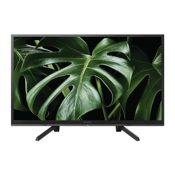
Sony KDL-50W660G Service Manual

Sony KDL-50W660G Service Manual

Gn5un chassis
Hide thumbs Also See for KDL-50W660G:

Advertisement

Quick Links

SERVICE MANUAL (UNIQUE)
ORIGINAL MANUAL ISSUE DATE:
(See next page for revision )
Conditions of Use:
(1) Please use this information only for the purpose of performing repair, maintenance and/or configuration services of the Sony products
(hereinafter the "Repair services") under the service agreement entered into with the Sony group company (hereinafter the "Service
agreement"). Using this information for any purpose other than the purpose described foregoing is forbidden.
(2) Only the Authorized Servicer's officers, employees or subcontractors (including their officers and employees) whose duties justify a need-to-
know and who have agreed to hold confidential this information (collectively hereinafter the "Permitted users") are permitted to access and
use this information. To disclose or disseminate to any person other than the Permitted users is forbidden.
(3) Destroy or erase any and all portion of this information promptly in an irrecoverable and secure fashion after achieving the purpose
described in Section (1) above.
(4) Do not copy, replicate, reproduce, alter, translate, transmit, sell, lease, or distribute this information in whole or in part without the prior
written permission of the author.
(Notwithstanding foregoing, it is permitted to copy and distribute this information to the Permitted users.)
(5) Please notify immediately any leakage, loss, theft, misappropriation, or other misuse of this information by e-mail to the following address:
somk-gcs-tissnexim-adm@jp.sony.com
(6) In addition to the above, the terms and conditions of the Service agreement shall be applied to using this information.
Revision of Information:
This information may be changed or updated at any time without any prior notice. Please confirm that this information is up-to-date before
using it.
2019.03
GN5UN CHASSIS
Segment : SV
9-888-763-A1
LCD TV
Sony EMCS (M) Sdn. Bhd., SVPM
© 2019.03

Advertisement

Table of Contents
loading

Summary of Contents for Sony KDL-50W660G

  • Page 1 Conditions of Use: (1) Please use this information only for the purpose of performing repair, maintenance and/or configuration services of the Sony products (hereinafter the “Repair services”) under the service agreement entered into with the Sony group company (hereinafter the “Service agreement”).
  • Page 2 REVISION HISTORY Version Date Subject 2019.03 1. 1 Issue...
  • Page 3 MODEL LISTS MODEL REMOTE DESTINATION KDL-50W660G RMT-TX300U KDL-50W665G RMT-TX300B KDL-50W667G RMT-TX300B...
  • Page 4: Table Of Contents

    TABLE OF CONTENTS Section Title Page DISASSEMBLY AND REMOVAL CAUTION 1-1. Rear Cover Disassemble and Re-Assemble Method 1-2. Guide Light Disassemble Method DIAGRAMS 2-1. Circuit Board Location 2-2. Wire Dressing KDL- 50W6*G EXPLODED VIEWS AND PARTS LIST TV SIZES 3-1. KDL- 50W6*G Please refer Service Manual –...
  • Page 5: Disassembly And Removal Caution

    SECTION 1 DISASSEMBLY AND REMOVAL CAUTION 1-1 Rear Cover Disassemble and Re-assemble Method and Caution 1. Dummy Card PCMCIA dismantle guide (before removing rear cover) ( For Europe model only ) Pull up dummy card PCMCIA...
  • Page 6 1-1 Rear Cover Disassemble and Re-assemble Method and Caution 1. Screw type & qty to disassemble RC 50” Reference 50” Remarks 4-167-019-22 Screw, +PSW M3X8 7-685-647-79 Screw, +BVTP 3X10 Type 2 IT-3...
  • Page 7 1-1 Rear Cover Disassemble and Re-assemble Method and Caution 2. Disassemble bottom hook a. Confirm hook position b. 1 hand hold top RC to unhook c. 1 hand push ruler to insert at hook area Note: Please wrap end of ruler with 3.
  • Page 8 1-2 Rear Cover Sharp Edge Information Caution Point: Please wear glove while removing rear cover to avoid sharp edge At bottom area as shown in figure below. Sharp edge corner Sharp edge corner...
  • Page 9: Guide Light Disassemble Method

    1-3 Guide Light Disassemble Method Method 1: Disassemble In Set Condition Hold here for both L&R sides 3. Pull Guide Light out 2. Rotate Guide Light slightly 1. Hold the end of Guide Light Note: Ensure Hook is not broken Prepare replaceable new part in case hook broken...
  • Page 10 1-3 Guide Light Disassemble Method Method 2: Disassemble Bezel First Step 1: Disassemble entire Bezel from P-mod/Set together with guide light (PTT) A attached. Step 2: Use a jig or pen to press on this hook area while pull the guide light (PTT) A out Press this hook area here Press this hook area here...
  • Page 11 It is difficult to remove the Light Guide from Bezel Lock (Hook) without damaging the Hook.
  • Page 12: Diagrams

    SECTION 2 DIAGRAMS 2-1 Circuit Board Location 2-1-1. 50” BPA BOARD UNIVERSAL SIL-TU SWITCH CARD, WIRELESS UNIT LKP2 BOARD...
  • Page 13: Wire Dressing

    2-2 Wire Dressing : 50” CONNECT INFORMATION INFORMATION CONNECT...
  • Page 14 2-2 Wire Dressing : 50” INFORMATION INFORMATION INFORMATION INFORMATION...
  • Page 15 2-2 Wire Dressing : 50” CONNECT INFORMATION INFORMATION CONNECT...
  • Page 16 2-2 Wire Dressing : 50” INFORMATION INFORMATION INFORMATION INFORMATION...
  • Page 17 2-2 Wire Dressing : 50” INFORMATION TAPE CONNECT INFORMATION...
  • Page 18 2-2 Wire Dressing : 50” INFORMATION INFORMATION INFORMATION CONNECT...
  • Page 19 2-2 Wire Dressing : 50” TAPE TAPE TAPE CONNECT...
  • Page 20 2-2 Wire Dressing : 50” CONNECT INFORMATION WIRE DRESSING...
  • Page 21 2-2 Wire Dressing : 50” WIRE DRESSING INFORMATION CONNECT...
  • Page 22 2-2 Wire Dressing : 50” WIRE DRESSING CONNECT CONNECT INFORMATION...
  • Page 23 2-2 Wire Dressing : 50” TAPE TAPE INFORMATION CONNECT...
  • Page 24 2-2 Wire Dressing : 50” WIRE DRESSING CONNECT...
  • Page 25 2-2 Wire Dressing : 50” WIRE DRESSING TAPE...
  • Page 26: Kdl- 50W6*G

    SECTION 3 EXPLODED VIEWS AND PART LISTS  (*) Parts are not stocked since they are seldom required for routine service. •Place the TV set facing downwards on a stable, level surface before disassembly and assembly of parts. • and shaded parts are critical for safety. Replace only with part number specified. Some delays should be anticipated when ordering these components.
  • Page 27: Kdl- 50W6*G

    3-2. KDL- 50W6*G Exploded View KDL-50W665G KDL-50W667G KDL-50W660G REF. NO PART NO. DESCRIPTION REAR COVER (M PTT) A 4-724-445-02 • 4-724-445-22 REAR COVER (M PTT) A • • LOUDSPEAKER,FY18 4X10CM 1-859-255-11 • • • BRACKET, TOP PCMCIA (PTT) - Not available for America region -...
  • Page 28 3-2. KDL- 50W6*G Screws *under board Screw Type Quantity Torque (N.m) SCREW +BVTP 3X10 TYPE2 IT-3 7-685-647-79 0.6 ± 0.1 SCREW, +PSW M3X8 4-167-019-22 0.4 ± 0.05 SCREW, +PSW M3X6 4-472-518-11 0.4 ± 0.05 SCREW, +LH M3x3(PUC) 4-690-738-01 0.4 ± 0.05...
  • Page 29 3-2. KDL- 50W6*G Connectors REF. NO PART NO. DESCRIPTION REMARKS 1-910-806-22 CN9602(BPA/BPE)-CN1(3KEY)-CN100(HKT) / CN4001(LKP2)-SP(1) HARNESS ASSY CN8500(BPA)-SOURCE BOARD (1) 1-912-555-11 FLEXIBLE FLAT CABLE 51P 1-912-565-11 FLEXIBLE FLAT CABLE 5P CN9500(BPA)-WIFI (1) 1-912-586-11 FLEXIBLE FLAT CABLE 40P CN9601(BPA)-CN9901(LKP2)(1)
  • Page 30 3-2. KDL- 50W6*G Other Parts KDL-50W665G KDL-50W667G KDL-50W660G PART NO. DESCRIPTION 1-493-490-12 AC ADAPTOR (120W) • ASSY,FALL LOCK,BELT LL 4-535-064-14 • • • BAG, SCREW ASSY (M4L10) 5-000-745-01 • • • [ Includes screw 4-159-298-01 SCREW, +PSW M4X10 ] 1-849-876-11 POWER-SUPPLY CORD SET •...
  • Page 31 Sony EMCS (M) Sdn. Bhd. English SVPM 9-888-763-A1 © 2019.03...

This manual is also suitable for:

Kdl-50w665gKdl-50w667g

Table of Contents